1
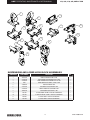
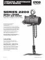
OPERATING, MAINTENANCE & PARTS MANUAL SERIES 2200 SMALL FRAME PILOT AIR HOIST Capacity from 1/4 (250kg) to 1 metric ton (1000kg) Follow all instructions and warnings for inspecting, maintaining and operating this hoist. The use of any hoist presents some risk of personal injury or property damage. That risk is greatly increased if proper instructions and warnings are not followed. Before using this hoist, each operator should become thoroughly familiar with all warnings, instructions and recommendations in this manual. Retain this manual for future reference and use. Forward this manual to the hoist operator. Failure to operate the equipment as directed in manual may cause injury. Should you have any questions regarding this product, please call Columbus McKinnon. The hoisting equipment described in this manual is intended for industrial use only and should not be used to lift, support or otherwise transport people. LOAD RATINGS Before installing, make certain the capacity of the hoist does not exceed the capacity of the trolley and the supporting structure is capable of supporting the load, hoist and trolley. MAINTENANCE / INSPECTION The trolley should be inspected periodically for evidence of excess wear or overload and its continued ability to support the load. The frequency of inspection will depend on the severity of use. It is recommended that the user begin with a monthly inspection and extend periods to quarterly, semi-annually or annually based on monthly experience. Any worn parts should be replaced immediately. November 2013 P/N: 11720901 REV. AA 11/2013 HOIST OPERATING, MAINTENANCE & PARTS MANUAL 1/4, 3/8, 1/2, 3/4, AND 1 TON TABLE OF CONTENTS SECTION PAGE Description ................................................................................................. 1 General Information .................................................................................... 2 Installation ...............................................................................................2-4 Operation .................................................................................................5-7 Lubrication ............................................................................................ 5 & 8 Maintenance ..........................................................................................7-11 Disassembly and Reassembly ............................................................11-18 Inspection Schedule and Maintenance Report......................................... 19 Recommended Practices.......................................................................... 20 Parts List and Illustrations ...................................................................21-27 Troubleshooting Chart and Notes........................................................28-29 Warranty.................................................................................................... 32 Airstar SERIES 2200 CAH SERIES 2200 BAH SERIES 2200 YAL SERIES 2200 SERIES 2200 SMALL FRAME PILOT AIR HOIST 2 Part No. 11720901 Rev. AA HOIST OPERATING, MAINTENANCE & PARTS MANUAL This book contains important information to help you install, operate, and maintain your new air hoist. We recommend that you study its contents thoroughly before putting your hoist to use. Through proper installation, application of correct operating procedures, and by practicing the recommended maintenance suggestions you will be assured maximum service from your hoist. Replacement parts information is included in this book for your convenience. Since it will likely be a long time before parts information is needed, we suggest that, after you have become familiar with operation and preventive maintenance procedures, this book be carefully filed for future reference. The air hoists are built in accordance with the specifications herein and at the time of manufacture comply with our interpretation of applicable sections of ANSI/ASME B30.16 "Overhead hoists". ANSI/ASME HST-5M "Performance standards for air chain hoists" and Occupational Safety and Health Act, 1970. EQUIPMENT ILLUSTRATED AND DESCRIBED HEREIN IS NOT DESIGNED OR SUITABLE FOR LIFTING OR LOWERING PERSONS. 1/4, 3/8, 1/2, 3/4, AND 1 TON GENERAL INFORMATION INSTALLATION 1. Air hoists are precision built chain type hoists which are built in five rated loads, 1/4, 1/2, and 1 ton. Each size is available in pull cord control and pendant throttle control models. All models come with coil type chain and include variations of hook and lug type suspensions. Coil chain hoists are also provided in spark resistant models. (Note: Spark resistant models have rated loads of 3/8 and 3/4 ton.) Air hoists are completely lubricated and load tested before being shipped from the factory. To place hoist in service, attach to a suitable overhead suspension in area to be used; connect hoist to nearest air supply; and check and adjust hoist speed. 2. All sizes and models are of the same basic design, having many common and interchangeable parts. They consist primarily of an aluminum alloy frame which houses a vane type air motor, chain sprocket wheel, and gearing. A shoe-type brake is mounted on one end of frame and is encased in an aluminum alloy end cover. A control head assembly with builtin muffler and air inlet swivel connection is mounted on opposite end of frame. An upper suspension hook is attached to the top of the frame. An alloy steel coil type load chain with spring-latch type lower block assembly is employed to raise and lower loads. A block and chain operated limit stop lever is mounted at bottom of frame and is pinned to throttle valve control shaft. Hoist operation is controlled by a pendant throttle control assembly. 3. The main difference between hoist models are in the type of control and type of suspension employed. Differences between sizes are in reeving of the load chain. On 1/4 and 1/2 ton hoists, the load chain is single reeved (one part of chain); on 1 ton hoists, the chain is double reeved (two parts of chain). The coil type chain is full-flexing, electric welded, link chain; carburized alloy chain on standard models and surface hardened chrome-nickel stainless steel on spark resistant models. Control differences are in methods employed for operating the hoist. There are two types, pull cord control and pendent throttle control. There are further described on page 6, figures 6 and 7. Suspension differences include a conventional hook type mounting and a lug type mounting. Hook suspension allows portability, permitting hoist to be easily moved from job to job. Lug suspension allows rigid trolley mounting of hoist on an overhead I-beam to permit traversing hoist and load. Rigid mounting of trolley on hoist affords maximum headroom advantage, saving space compared to a hoist hooksuspended on a trolley For specifications and dimensional data, see Figure 1 on page 3. SUSPENDING HOIST 1. On hook suspended hoists, select a suitable overhead support in area hoist is to be used (one capable of holding combined weight of hoist and its rated load) and hang hoist up. Be certain that upper hook is firmly seated in center of hook saddle and that the spring safety latch is properly closed over hook opening. In some cases, it may be necessary to first remove spring latch before hook will fit over a support. Reinstall latch after hook is engaged. 2. On lug suspended hoists, select a suitable overhead support in area hoist is to be used (one capable of holding combined weight of hoist and its rated load). Mount hoist using through bolts of appropriate size to fit mounting holes in suspension lug at top of hoist. Use only suspension bolts provided by CMCO. (see Basic Hoist Data) 3. On rigid mount trolley suspended hoists, the trolley side plates must be properly spaced so trolley will fit (beam on which hoist will operate). Adjustment for various I-beam sizes is accomplished by rearrangement of spacer washers on through bolts which connect trolley side plates to hoist suspension lug. Refer to instruction sheet furnished with Rigid Mount Trolleys for complete instructions. The structure used to suspend hoist must be of sufficient strength to withstand reasonable forces to which hoist and support may be subjected. Hoist must be aligned with load to avoid side pulls. If trolley is mounted on an open-end beam, end stops must be installed to prevent trolley from running off the end of the beam resulting in injury to operator and others, and damages to load and other property. SERIES 2200 SMALL FRAME PILOT AIR HOIST 3 Part No. 11720901 Rev. AA HOIST OPERATING, MAINTENANCE & PARTS MANUAL 1/4, 3/8, 1/2, 3/4, AND 1 TON 18.0 4.2 4.2 5.7 5.7 5.0 STANDARD HOOKS 1/4, 1/2 TON STANDARD HOOKS 1 TON 5.0 6.9 6.9 EXHAUST 1/2 NPT INLET 3/8 NPT 2X 13.0 .688 .813 15.6 4.2 4.500 3.125 1.563 1.563 4.2 3.125 5.7 2X .688 5.7 .813 CROSS MOUNT 1/4 & 1/2 TON 5.0 CROSS MOUNT STANDARD HOOK 1 TON 3.625 1.812 5.0 3.625 6.9 6.9 EXHAUST 1/2 NPT INLET 3/8 NPT Figure 1– Specifications and Dimensional Data BASIC HOIST DATA *Rated Loads: 1/4, 1/2, and 1-Ton Air Pressure Recommended: 90 psi Air Consumption: 48 SCFM at 90 psi Net Weight (Basic Hoist): 36 lbs SERIES 2200 SMALL FRAME PILOT AIR HOIST When ordering replacement parts, please provide the following information: - Model number - Serial number - Part description and number as shown in parts list 4 Suspension: Hook and lug Control: Pull Cord or Pendent Throttle Air Inlet Size: 3/8 NPTF Air Supply Hose: 1/2 I.D. min. Air Exhaust: 1/2 NPTF Part No. 11720901 Rev. AA HOIST OPERATING, MAINTENANCE & PARTS MANUAL INSTALLATION (CONTINUED) 2. If chain container is to be used on hoist, install it following instructions furnished with container. CONNECTING HOIST TO AIR SERVICE 1. Connect hoist to nearest filtered and lubricated air source using minimum 1/2" I.D. air hose assembly (See Figure 2). Avoid use of reducing bushing and nipple or hose assemblies of smaller diameters which may cause restrictions. 2. If hoist is suspended by trolley, provide sufficient hose to reach from air source to farthest point of trolley travel. Air Inlet Swivel 4. The recommended operating air pressure for all capacities of Series 2200 is 90 psi. When line pressure exceeds 100 psi (while hoist is operating), it is recommended that a pressure regulator valve be provided in the air supply line to maintain proper pressure. However, there is a wide range of pressures within which the hoists will operate. Refer to "Hoist Performance Charts" (See Figure 5 on next page). HOISTING AND LOWERING SPEED ADJUSTMENTS 1/4, 3/8, 1/2, 3/4, AND 1 TON 3. When the screwdriver slots on ends of adjusting screws are horizontal (hoist in normal suspended position), the hoist speeds will be at either minimum speed or maximum speed. Rotating the screws 180° in either direction will give a full adjustment between minimum and maximum speed limits. NOTE: Screws have arrow stamped on end to assist operator with adjustment. NOTE: Refer to page 19 for Recommended Practices for Air Powered Hoists. 1. Hoist speed is adjusted at the factory to give maximum lifting speed and is set at average between minimum and maximum lowering speed. 2. To adjust the hoisting or lowering speed, turn appropriate regulator screw (Figure 4) in either direction a little at a time while operating hoist under load. 1/2" I.D. Pressure Hose 3/8" NPTF Male Pipe Thread Maximum lowering speed with rated load is very high. Adjust with care. Heads of adjusting screws should not extend beyond outer surface of housing. Figure 2– Connecting Air Hose to Hoist 3. A filter and lubricator unit (Figure 3) must be installed between air source and air hose leading to hoist. These keep the air flowing to the hoist free of dirt and adds lubricant to the air so internal parts of motor are constantly lubricated. Use air hoist motor oil or good grade 10W machine oil (approximate viscosity 150 SSU at 100°F). Multi-viscosity, detergent type engine oil is not recommended. Feed one drop of oil for every 50 to 75 cubic feet of air going through the air motor. In Flow "Down" Adjusting Screw "Up" Adjusting Screw Figure 4– Hoisting and Lowering Speed Adjustment Out Filter Oiler Figure 3– Air Filter and Lubricator Unit SERIES 2200 SMALL FRAME PILOT AIR HOIST 5 Part No. 11720901 Rev. AA HOIST OPERATING, MAINTENANCE & PARTS MANUAL OPERATION Operation is controlled by either pull cords or a pendant throttle control, depending on the model. Pull Cord Control models have pull type control cords suspended from a rocker type lever at bottom of hoist that actuates the throttle control vale. Pendant Throttle Control models have a convenient lever type control valve handle suspended from the control cylinders on sides of control head housing. Do not lift more than rated load except for test purposes. Overloading hoist can result in chain breakage, hook deformation and other failures which can cause serious injury and damage. A test at greater than rated load should be a properly supervised official test only, not an operator test. If any load sustaining parts have been altered, replaced or repaired, hoist should be load tested at 125% of rated load by a designated, qualified person, with a written report recording test load, as recommended in ANSI B30.16 Safety Standards. 1/4, 3/8, 1/2, 3/4, AND 1 TON PULLING AND PIVOTING HOIST AND LOAD 2. Pull Cord Control a. Pull top handle (marked with arrow pointing up) down to raise load. 1. On pendant throttle control, the valve handle is supported by a strain cable that is suitable for pulling trolley suspended hoists when empty or lightly loaded. Push on load or load chain to traverse heavily loaded hoists. b. Pull bottom handle (marked with arrow pointing down) down to lower load. c. Release handle being used to stop either lifting or lowering. d. Speed of lifting and lowering is varied between slowest (inching) to full speed by the pull exerted on control handle being used. 1/4 TON RATED LOAD HOIST Load 125 LBS. Air Pressure psiG UP 250 LBS. DOWN UP 500 LBS. DOWN UP DOWN Min. Max. Min. Max. Min. Max. Min. Max. Min. Max. Min. Max. 0 0 0 5 8 0 0 15 40 0 0 25 65 60 35 70 30 75 30 65 35 85 20 50 40 95 PRE-OPERATIONAL CHECKS 70 40 75 30 80 35 70 35 85 25 60 40 95 Check the following before operating hoist with load: 80 40 80 35 80 35 75 35 85 30 60 40 95 90 40 80 35 80 35 80 35 85 30 65 40 95 100 40 80 35 80 40 80 35 85 30 65 40 95 1. Inspect chain anchor connections at side of hoist frame and at upper hook on 1 ton double reeved models. Anchor screw or pin should be secure and not bent or broken. Chain should be solidly anchored. 2. Check hoist brake for proper adjustment and operation (See "Maintenance," page 9). 3. Check hooks. They should not be bent or distorted and should not be opened beyond the correct opening sizes given in Figure 11. Hook latches should not be bent or damaged and springs not broken. 4. Check chain to make sure it is not twisted or kinked. Be sure lower block (3/4 and 1 ton, double reeved models) has not been capsized. 5. Lubricate chain (See "Lubrication," page 7). Never operate hoist with defective chain anchor pins, brake or hooks. OPERATING HOIST With hoist installed and air pressure turned on, hoist is operated in the following manner: 1. Pendant throttle control 1/2 TON RATED LOAD HOIST Load 250 LBS. 500 LBS. 1000 LBS. 0 0 0 15 40 0 0 25 65 0 0 45 125 60 30 65 35 85 20 50 40 95 0 20 45 125 70 35 70 35 85 25 60 40 95 0 30 50 120 80 35 75 35 85 30 60 40 95 10 40 55 120 90 25 80 35 85 30 65 40 95 15 45 55 120 100 40 80 35 85 30 65 40 95 20 50 55 120 1 TON RATED LOAD HOIST Load 500 LBS. 1000 LBS. 2000 LBS. 0 0 0 8 20 0 0 13 33 0 0 25 65 60 15 32 16 42 10 25 20 50 0 10 25 65 70 16 35 17 42 12 30 20 50 0 15 25 60 80 17 37 18 42 14 31 20 48 5 20 30 60 90 18 40 18 42 15 32 20 47 7 23 30 60 100 20 40 18 42 15 34 20 45 10 25 30 60 NOTE: Hoist Speeds are shown in feet per minute (f.p.m.). Figure 5– Hoist Performance Charts a. Depress throttle valve lever marked "UP" to raise load (See Figure 6). b. Depress throttle valve lever marked "DOWN" to lower load. c. Release lever being depressed to stop either lifting or lowering. d. Speed of lifting and lowering is varied by the position of the throttle valve lever being depressed. SERIES 2200 SMALL FRAME PILOT AIR HOIST 6 Part No. 11720901 Rev. AA HOIST OPERATING, MAINTENANCE & PARTS MANUAL 1/4, 3/8, 1/2, 3/4, AND 1 TON OPERATION (CONTINUED) UPPER AND LOWER LIMIT STOPS A lower block and chain operated limit stop is provided to guard against overtravel of load in either raising or lowering direction, which can cause damage to hoist. When highest position is reached, the lower block trips the control lever (Figure 7). When lowest position is reached, the tail end of load chain trips the control lever (Figure 8). The control lever is connected to the control shaft which actuates inlet valves controlling air pressure to air motor. Limit stops are intended as safety devices and should not be used as a routine basis to stop travel of lower block or shut off hoist. Limit Lever Lower Block Figure 7– Control Lever Being Tripped by Lower Block OPERATING PRECAUTIONS Equipment covered herein is not designed or suitable as a power source for lifting or lowering persons. Safe operation of an overhead hoist is the operator's responsibility. Listed below are some basic SHALL and SHALL NOT rules that can make an operator aware of dangerous practices to avoid and precautions to take for his own safety and the safety of others. Observance of these rules in addition to frequent examinations and periodic inspection of the equipment may save injury to personnel and damage to equipment. To avoid potentially hazardous situations, the operator shall: Figure 6– Pendant Throttle Control Handle 5. Always be sure there is no twist in coil load chain. On 1 ton hoists, check to see that lower block is not capsized between strands of chain. 6. Check both upper and lower limit stop operation by raising or lowering empty hook to limit of travel. Hoist must shut off. 7. When lifting load, make certain it is free to move and will clear all obstructions. 1. Operate hoist cautiously to become familiar with its performance. 8. Stand clear of all loads and never lift or travel loads over people. 2. Not load hoist beyond rated load. 9. Avoid operating hoist when hook is not centered under hoist. Be sure that hoist trolley or other support mechanism is correctly positioned for handling the load before lifting. 3. Take up chain slack carefully to avoid jerking load. 4. Not use hoist load chain as a sling. Tail End of Load Chain Limit Lever Figure 8 – Control Lever Being Tripped by Tail End of Load Chain 10.Guide load so as to have it under control at all times. 11.Not operate hoist with twisted, kinked or damaged chain. 12.Not operate damaged or malfunctioning hoist. SERIES 2200 SMALL FRAME PILOT AIR HOIST 7 Part No. 11720901 Rev. AA HOIST OPERATING, MAINTENANCE & PARTS MANUAL OPERATION (CONTINUED) 13.Conduct periodic visual inspection for signs of damage or wear. 14.Observe inspection and maintenance procedures described in this manual. 15.Not lift or transport a load until all personnel are clear. Never lift people on hook or load. 16.Not divert attention from load while operating hoist. Never leave a suspended load unattended. 17.Not use limit stop as normal operating stop. This is a safety device only. 18.Not "jog" unnecessarily. 19.Personnel not physically fit or properly qualified, shall not operate hoist. 20.Not remove or obscure warning labels. 21.Use common sense and best judgment whenever operating a hoist. Observe American National Standard Safety Standard, ANSI B30.16, latest issue. Refer to page 19 for complete list of HMI SHALL's and SHALL NOT's. LUBRICATION The lubrication services outlined in this section should be performed at regular intervals to maintain top hoist performance and insure long life. Frequency of lubrications will depend on type of hoisting service hoist is subjected to and should coincide with preventive maintenance inspections (See "Maintenance"). SERVICE AIR LINE LUBRICATOR Servicing air line filter and lubricator unit is of primary importance since it is the only source of lubrication for control valves and air motor. Fill lubricator with air hoist motor oil or good grade 10W machine oil (approximate viscosity 150 SSU at 100°F). Multi-viscosity, detergent type engine oil is not recommended. GEARCASE The gearcase is grease packed at the factory and requires no further greasing unless the gearcase is for any reason disassembled. Then, at reassembly, the parts should be washed clean (using commercial fluid) and repacked with NLGI EP-2 Grease. 1/4, 3/8, 1/2, 3/4, AND 1 TON LUBRICATE LOAD CHAIN MAINTENANCE A small amount of lubricant will greatly increase load chain life; therefore, chain should not be allowed to run dry. Chain should be cleaned and lubricated as directed in paragraph below. User should set up a regular schedule for chain lubrication after observing operating conditions for a few days. Use Bar and chain oil (LUBRIPLATE or equal) on load chain. 1. Preventive maintenance services required on air hoists are, for the most part, simple periodic inspection procedures to determine condition of hoist components. Below are suggested inspection procedures based on daily average hoist usage. Hoist subjected to severe service or to adverse environments should be examined weekly or as conditions warrant. COIL CHAIN Under ordinary conditions, only weekly attention will be necessary for alloy steel chain. Under hot and dirty conditions, it may be necessary to clean chain at least once a day and lubricate it several times between cleanings. Thoroughly clean chain with an oil solvent and relubricate by coating it lightly with penetrating oil and graphite. Make sure that lubricant coats wear surfaces between links. LUBRICATE UPPER HOOK AND LOWER BLOCK ASSEMBLY THIRTY-DAY INSPECTION Hoist may be left suspended. INSPECT LOAD CHAIN Operate hoist under load and observe operation of chain over sprocket in both directions of chain travel. Chain should feed smoothly into and away from the sprocket. If chain binds, jumps or is noisy, first see that it is clean and properly lubricated. If trouble persists, inspect chain and mating parts for wear, distortion or other damage. 1. On 3/4 and 1 ton hoists, apply a few drops of SAE 60 oil on shank of upper hook where it enters suspension bracket. 2. On single line hoists (1/4, 3/8 and 1/2 ton) disassemble upper and lower hooks as described in "Disassembly and Reassembly," page 10 and grease thrust bearings with a good grade of bearing grease. 3. On double line hoists (3/4 and 1 ton) lower blocks, disassemble as described in "Disassembly and Reassembly," page 11 and grease needle bearings for sprocket shaft and hook with a good grade of bearing grease. LUBRICATE CONTROL SHAFT, BRAKE CAM AND VALVE SHIFTER 1. Apply a few drops of SAE 60 oil on control shaft at bearing points. 2. Apply graphite grease on valve shifter and on brake cam. LUBRICATE TROLLEY WHEEL BEARINGS If hoist is mounted on a trolley, apply light grease to wheel bearings as recommended by trolley literature. Before performing any internal work on hoist, remove load and be certain air is shut off. SERIES 2200 SMALL FRAME PILOT AIR HOIST 8 Part No. 11720901 Rev. AA HOIST OPERATING, MAINTENANCE & PARTS MANUAL 1/4, 3/8, 1/2, 3/4, AND 1 TON MAINTENANCE (CONTINUED) 1. Coil type load chain. Clean chain for inspection. Examine visually for gouges, nicks, weld splatter, corrosion or distorted links. Slacken chain and check bearing surface between links for wear, Figure 9. Greatest wear will often occur at sprocket at high or low point of lift, particularly when hoist is subjected to repetitive lifting cycles. Case hardness of chain is approximately .015" deep. Chain must be replaced before the case is worn through. Also check chain for elongation using a vernier caliper (See Figure 10). Select an unused, unstretched section of chain (usually at the loose end). Suspend the chain vertically under tension and using a blade type caliper gauge, measure the outside length of any convenient number of links approximately 12" to 24". Measure the same number of links in the use sections and calculate the percentage in increased length. Replace if length of the used portion is more than 1 1/2% longer than the unused portion of the chain. Based upon ASME B30.16. Chain with excessively pitted, corroded, nicked, gouged, twisted or worn links should be replaced using only factory approved chain. Never weld or attempt to repair coil chain. Load chain for spark resistant models is made of stainless steel. Surface hardness treatment and the core is lower in hardness than standard alloy steel load chain. For these reasons the rated capacity of spark resistant models is lower than that of standard models. Figure 9– Check Chain Wear at Bearing Surfaces between Links Do not assume that load chain is safe because it measures below replacement points given herein. Other factors, such as those mentioned in visual checks above, may render chain unsafe or ready for replacement long before elongation replacement is necessary. When replacing load chain, Use only CM supplied load chain. Using other than CM supplied load chain may cause the chain to jam in the hoist and / or allow the chain to break and the load to drop. Figure 10– Checking Coil Chain Using Vernier Caliper SERIES 2200 SMALL FRAME PILOT AIR HOIST 9 Part No. 11720901 Rev. AA HOIST OPERATING, MAINTENANCE & PARTS MANUAL MAINTENANCE (CONTINUED) 2. Check anchor end of chain at side of hoist frame for damage to last link. Replace damaged parts. 3. Check connection of chain to lower block on 1/4, 3/8 and 1/2 ton hoists. Replace parts showing evidence of damage, twisting or elongation. 4. Check connection of chain to anchor on side of suspension bracket on double reeved 3/4 and 1 ton 1 ton hoists. Replace parts showing evidence of damage, twisting or elongation. 5. Lubricate load chain if required (See "Lubrication," page 7). INSPECT LOWER BLOCK 1. Check for bent or distorted hook. Per ASME B30-10 Hooks shall be removed from service if damage such as the following is visible: – Excessive pitting or corrosion, cracks, nicks or gouges. – Wear—any wear that exceeds 10% of the original section dimension of the hook or its load pin. – Deformation—any visibly apparent bend or twist from the plane of the unbent hook. – Throat opening—any distortion causing an increase in the throat opening of 5% not to exceed 1/4". – Inability to lock—any self-locking hook that does not lock. – Inoperative latch—any damaged latch or malfunctioning latch that does not close the hook's throat. – Thread wear, damage or excessive corrosion. – Evidence of excessive heat exposure or unauthorized welding. – Evidence of unauthorized alterations such as drilling, machining, grinding, or other modifications. – Also check to see that hook swivels. Lubricate if necessary. 1/4, 3/8, 1/2, 3/4, AND 1 TON CHECK BRAKE OPERATION Hooks, upper or lower, damaged from chemicals, deformation or cracks or having more than 15 percent in excess of normal throat opening or more than 10 degrees twist from the plane of the unbent hook, or opened, allowing the hook latch to bypass hook tip must be replaced. Any hook that is twisted or has excessive throat opening indicates abuse or overloading of the hoist. Other load bearing components of the hoist should be inspected for damage (See paragraph 3 under "ANNUAL INSPECTION" on next page). INSPECT UPPER SUSPENSION 1. On hook suspended models, check for bent or distorted hook. Per ASME B30-10 Hooks shall be removed from service if damage such as the following is visible: – Excessive pitting or corrosion, cracks, nicks or gouges. – Wear—any wear that exceeds 10 % of the original section dimension of the hook or its load pin. – Deformation—any visibly apparent bend or twist from the plane of the unbent hook. – Throat opening—any distortion causing an increase in the throat opening of 5% not to exceed 1/4 ". – Inability to lock—any self-locking hook that does not lock. 1. With air turned on and with rated load attached to lower hook, operate hoist to raise load, applying pressure to throttle control lever. If load drifts down before the motor starts to actuate, the brake is out of adjustment. 2. To adjust brake, insert hex key through hole in brake cover. Turn screw counterclockwise to tighten brake or clockwise to loosen brake (See Figure 24). ANNUAL INSPECTION Hoist must be disconnected from air service and removed from overhead suspension. Hoists subjected to severe service or to adverse environments should be examined weekly or as conditions warrant. 1. Hoist should be partially disassembled as necessary to inspect hoist parts noted in paragraphs 2 through 8. below. Refer to "Disassembly and Reassembly" steps on page 10. 2. Inspect brake. Remove brake housing cover and brake shoes as outlined in "Disassembly and Reassembly," page 11. Check brake shoe linings and brake wheel for wear and scoring. Replace badly worn or scored parts. Check condition of brake cam and spring. Replace any damaged parts. 3. Inspect internal load gears. Remove gear plate and intermediate gears as outlined in "Disassembly and Reassembly," page 13. Check condition of gear teeth on internal gear, intermediate gears, and motor shaft pinion. Replace worn or damaged parts. – Inoperative latch—any damaged latch or malfunctioning latch that does not close the hook's throat. – Thread wear, damage or excessive corrosion. – Evidence of excessive heat exposure or unauthorized welding. – Evidence of unauthorized alterations such as drilling, machining, grinding, or other modifications. – Also check to see that hook swivels. Lubricate if necessary. 2. On 3/4 and 1 ton hoists, check sprocket and bearings in lower block for freedom of movement and signs of damage. Lubricate if necessary. Replace damaged parts. MEASURE OPENING 3. Check hook latches. Replace damaged or bent latches or broken springs. 2. On push trolley suspended models, check condition of trolley parts and lug bracket. Replace bracket or any trolley parts which are damaged or cracked. 3. Check hook latch. Replace damaged or bent latch or broken spring. SERIES 2200 SMALL FRAME PILOT AIR HOIST 10 Part No. 11720901 Rev. AA HOIST OPERATING, MAINTENANCE & PARTS MANUAL MAINTENANCE (CONTINUED) 4. Inspect chain sprocket and Bearings. Remove sprocket and internal gear as a unit, "Disassembly and Reassembly," page 13. Check condition of pockets on chain sprocket and inspect ball bearing assemblies. Replace worn or damaged parts. 5. Inspect throttle valve shifter. Remove valve shifter and control shaft (See "Disassembly and Reassembly, page 12) and shifter pin (See "Disassembly and Reassembly," page 11). Check condition of shifter, pin and shaft bearings. Replace worn or damaged parts. 6. Inspect throttle valve housing. Remove throttle housing assembly (See "Disassembly and Reassembly," page 12) and disassemble it as outlined. Check condition of throttle valve, valve bushing (in housing) and "O" rings on valves. Replace worn or damaged parts. 7. Inspect air motor. Remove air motor assembly from hoist (See "Disassembly and Reassembly," page 12). Check motor for condition of bearings, possible rotor rubbing on body or end plates, blade freedom in rotor slots, shaft and gear. If motor appears to be in good condition, do not service other than lubricating well with light oil. 8. Reassemble and test hoist. Reassemble hoist as outlined in "Disassembly and Reassembly," page 14. After reassembly, test hoist in accordance with "Disassembly and Reassembly,"page 16. SERIES 2200 SMALL FRAME PILOT AIR HOIST DISASSEMBLY AND REASSEMBLY GENERAL 1. The following disassembly and reassembly instructions apply to all models of air hoists. Where needed, variations to instructions are provided to cover differences between models (suspensions, controls, load chain, capacity sizes) with applicable models specifically noted. 2. A complete teardown procedure is given. However, if only certain parts require repair or replacement, a partial teardown may be performed, using applicable portions of the instructions. 3. For easier handling during disassembly, the following disassembly steps may, where conditions permit, be completed before hoist is removed from its overhead suspension or disconnected from its air supply: Remove chain container, if hoist is so equipped. Remove lower block and load chain assembly, following procedure outlined in "Disassembly and Reassembly," below. 4. These hoists contain precision machined parts and should be handled with care at disassembly and reassembly. When removing or installing parts with press fits, be careful to apply pressure evenly. On ball bearings, apply pressure to face of inner or outer race, whichever is adjacent to mating part. This will avoid damage to bearing races from brinelling by pressing through bearing balls. Apply a thin film of oil to parts having a tight fit when installed. 11 1/4, 3/8, 1/2, 3/4, AND 1 TON DISASSEMBLY REMOVAL OF HOIST FROM OVERHEAD SUSPENSION 1. Turn off air at source. 2. Operate control to bleed air from hoist. 3. Disconnect air hose at inlet swivel. 4. Remove hoist from overhead suspension. REMOVAL OF LOWER BLOCK AND LOAD CHAIN ASSEMBLY 1. On models with single reeved load chains (1/4, 3/8 and 1/2 ton), disconnect end of load chain from tail end, anchor boss at side of hoist frame. Remove socket head cap screw, holding end link to tail end anchor on coil chain. If hoist is connected to air service, run chain out of hoist by operating control in "lowering" direction. If hoist is not connected to air service, the chain can be pulled out of hoist by hand while holding brake open by pulling down on control lever. 2. On models with double reeved chains (3/4 and 1 ton) , disconnect end of chain as in paragraph (1) above, run chain out of hoist by operating it in "lowering" direction, and disconnect opposite end of chain from anchor at side of upper suspension bracket. Part No. 11720901 Rev. AA HOIST OPERATING, MAINTENANCE & PARTS MANUAL DISASSEMBLY AND REASSEMBLY (CONTINUED) 3. On single reeved 1/4, 3/8 and 1 ton models, separate load chain from lower block assembly. Drive out small spring pin securing lower block pin in lower block and push out lower block pin to release chain. 4. Lower blocks (1/4, 3/8 and 1 ton) are of a pinned construction, permitting individual replacement of body, thrust bearing, or hook. To disassemble, drive spring pin from hook nut. With pin removed, hold hook nut from turning with drift punch and rotate hook to unscrew it from nut. Separate hook, bearing shield, needle bearing and two thrust washers from body. Hook and nut are drilled at assembly and are replaced only as an assembly. 5. On 3/4 and 1 ton (double reeved) models, the lower block assembly is disassembled by removing socket head screws and nuts holding body halves together. REMOVAL OF BRAKE COVER, CONTROL LEVER AND LOAD BRAKE. 1/4, 3/8, 1/2, 3/4, AND 1 TON 2. Remove two screws securing brake housing cover to frame and lift off cover. Control Lever 3. To remove control lever and shaft, drive spring pins from control lever (Figure 12) and valve shifter at end of shaft using a drift punch. Lightly tap valve shifter end of shaft and withdraw shaft by pulling on brake cam end (Figure 13). As shaft is withdrawn, valve shifter and control lever will fall free. 4. Remove brake spring by carefully prying it up evenly with a screwdriver until spring is about half-way off. Using brake spring spreader (Part No. 306989, Figure 14), remove spring from brake arms (Figure 15). Spring Drive Pin Valve Shifter Figure 12- Driving Spring Pin from Control Lever and Shaft Do not pry spring all the way off with screwdriver, since spring is apt to fly in most any direction with considerable force. 5. Remove brake shoes. Be sure not to lose steel fulcrum balls. 6. Remove steel balls from recesses in sides of upper brake boss. 1. On pendant throttle control, for convenience, disconnect control hoses from air cylinders, open strain cable "S" hook at eye bolt on throttle housing and remove pendant throttle control assembly from hoist. See "Disassembly and Reassembly," page 17 for disassembly and reassembly of pendant throttle control. Control Shaft Figure 13- Removing Control Shaft Brake Spring Spreader Part No. 306989 Figure 14- Special Tool for Removing Brake Spring SERIES 2200 SMALL FRAME PILOT AIR HOIST 12 Part No. 11720901 Rev. AA HOIST OPERATING, MAINTENANCE & PARTS MANUAL DISASSEMBLY AND REASSEMBLY (CONTINUED) REMOVAL AND DISASSEMBLY OF CONTROL HEAD ASSEMBLY Brake Spring 4. The throttle valve is retained in the control head by the valve shifter pin. The pin is assembled with Loctite on the threads and should not be removed for routine servicing. If valve is to be removed, use a hex key to remove pin from bottom of throttle valve (See Figure 22). The valve can now be removed from bushing in housing. The throttle valve bushing is pressed into place and honed to provide a .0001 to .0003 inch clearance with valve. If bushing is scored, worn, or otherwise damaged, the housing and bushing assembly should be replaced along with the valve. 5. Remove air inlet swivel body and bushing from top of housing. Retain bushing gasket for reuse. Pull strainer screen from housing bore. 1/4, 3/8, 1/2, 3/4, AND 1 TON Air Motor Figure 17 - Removing Motor from Frame 6. Remove retaining ring from bottom of swivel body and pull off bushing. Remove "O" ring seal from its groove in bushing. Figure 15 - Removing Brake Spring Using Special Tool Throttle Control Head Muffler Screen 7. Disassemble control cylinder (pendant throttle control models) by removing cylinder lock ring. Cylinder and cap will come off with lock ring. Lift out spring and then remove piston and seal assembly from cylinder. Piston shaft "O" ring seal and retainer washer will drop out as piston is removed. Gasket Air Motor REMOVAL AND INSPECTION OF AIR MOTOR 1. Remove air motor from hoist frame by placing entire unit on motor end and lifting frame straight up as shown. Do NOT tap on end of motor shaft since this will destroy critical rotor alignment and damage motor. If necessary, motor may be grasped at bearing boss on the dead end plate to assist in removal. Figure 16 - Removing Control Head Assembly 1. Remove control head assembly by taking out six socket head screws and lifting assembly from frame. 2. Lift muffler and screen from recess in control head housing. 3. On pendant throttle control models, remove control cylinder assemblies from each side of control head housing *figure 23). On pull cord control models, remove throttle valve spring retainer caps from each side of housing (figure 22). Valve springs, spring guides and "O" ring seals can now be removed from valve bore at each side of housing. SERIES 2200 SMALL FRAME PILOT AIR HOIST 2. Motor is a unit construction and should not be disassembled. Inspect end plates, rotor shaft and body for damage. If there is significant damage, replace the motor. 13 Part No. 11720901 Rev. AA HOIST OPERATING, MAINTENANCE & PARTS MANUAL DISASSEMBLY AND REASSEMBLY (CONTINUED) REMOVAL OF BRAKE WHEEL, INTERNAL LOAD GEARS AND SPROCKET 1. Rotate brake wheel until holes in web are aligned with four socket head cap screws (Figure 18). Remove screws, then lift brake wheel off (Figure 19) after prying up lightly and evenly with screwdriver to free ball bearing. Ball bearing and clamp plate are pressed off after removing retaining ring from wheel hub. 2. Remove four socket head screws securing gear plate to frame and lift off plate and intermediate gears as a unit (Figure 20). Do not remove the two socket head screws from flange around brake wheel bearing hole (Figure 19) unless it is necessary to replace intermediate gears. 1/4, 3/8, 1/2, 3/4, AND 1 TON 3. Remove four fillister head screws attaching chain guide and stripper assembly to hoist frame. This will free guide to allow sprocket to be pulled through it as it is removed in step (5) (See Figure 21). 4. Rotate internal gear (Figure 20) until holes in web align with six socket head screws securing bearing clamp plate to frame. Remove internal gear, chain sprocket and ball bearings as a unit (Figure 21). It may be necessary to tap sprocket to free ball bearings from bores in frame. 5. To disassemble intermediate gear, sprocket and ball bearing assembly, remove retaining ring and pull outer ball bearing from sprocket. Remove spindle nut from other end of sprocket and pull internal gear free of sprocket shaft. Remove clamp plate and pull off remaining ball bearing. Internal Gear Sprocket and Bearing Assembly Chain Guide and Stripper Assembly (Coil Chain) Figure 21- Removing Internal Gear, Chain Sprocket and Ball Bearing Assembly Brake Wheel Intermediate Gears Gear Plate Internal Gear Figure 18- Removing Cap Screws Securing Bearing Clamp Plate Figure 20- Removing Gear Plate and Intermediate Gears Ball Bearing Gear Plate Retaining Screw Figure 19- Removing Brake Wheel and Ball Bearing Assembly SERIES 2200 SMALL FRAME PILOT AIR HOIST 14 Part No. 11720901 Rev. AA HOIST OPERATING, MAINTENANCE & PARTS MANUAL DISASSEMBLY AND REASSEMBLY (CONTINUED) CLEANING AND INSPECTION Before reassembly, all parts should be thoroughly cleaned and inspected to determine their serviceability. Replace all parts that are excessively worn or damaged. Minor nicks and scratches should be filed to remove raised edges. NOTE: Bearings that are sealed are lubricated at the factory for normal life of the bearing and must not be washed. If they are exposed to wash or infiltration with foreign matter, they must be replaced. REASSEMBLY GENERAL The procedure to be followed to reassemble hoist is in reverse order of the disassembly steps outlined in "Disassembly and Reassembly," page 10. Listed below are special assembly precautions which should be observed to assure proper assembly. ASSEMBLY OF MOTOR INTO FRAME When reassembling motor, observe the following precautions: 1. Lubricate motor with small amount of Air Hoist Motor Oil or good grade 10W machine oil (approximate viscosity 150 SSU at 100°F). Multi-viscosity, detergent type engine oil is not recommended. 1/4, 3/8, 1/2, 3/4, AND 1 TON ASSEMBLY OF CONTROL HEAD At reassembly of control head and throttle valve, observe these precautions: 1. Lightly oil throttle valve and bushing with SAE 20 oil. If shifter pin was removed from valve, assemble valve with threaded hole facing slot at bottom of bushing in housing (Figure 22). Shifter pin should be assembled with loctite (277 or equivalent).. Extreme care must be taken not to get any loctite on valve outside diameter since this will lock up valve and scrap the complete head assembly. NOTE: Apply lubricating oil to "O" rings and "U" seals before installing and take care during installation so as not to cut, pinch, or otherwise damage them. 2. Use new "O" ring seals at each end of valve. Install spring guides and valve springs in bores on each side of housing and secure with control cylinders. Use new "O" ring gaskets. 3. At reassembly of control cylinders (pendant throttle control models), use new "U" type seals on piston heads and "O" ring seals on piston stems. Be sure "U" type seals face direction illustrated in Figure 23. 4. Use new "O" ring gaskets on adjusting screws. When installing screws in control head housing, turn them in until heads are flush or slightly below face of housing. Adjustment is accomplished during testing of hoist (See "Installation," page 4.) Figure 22 - Section View Showing Assembly of Throttle Valve, Springs and Valve Shifter in Control Head SERIES 2200 SMALL FRAME PILOT AIR HOIST 15 Part No. 11720901 Rev. AA HOIST OPERATING, MAINTENANCE & PARTS MANUAL DISASSEMBLY AND REASSEMBLY (CONTINUED) 3. Brake adjustment with load: a. With load on hook, press "UP" lever, slowly! Load must not creep down before motor starts. Turn adjusting screw out as required. 5. At reassembly of screen and air inlet swivel, install a new "O" ring seal inside swivel bushing. b. Brake must stop and hold load in both directions. 6. In mounting control head housing on hoist, use a new motor-to-head air seal gasket and a new head-to-frame gasket. INSTALLATION OF LOAD CHAIN Figure 24 - Brake Adjustments spring, using the spreader tool to start the spring over the shoes (See Figures 14 and 15). Tap the spring into place. Adjust brake shoes per instructions in Figure 24. 1.Brake adjustment at reassembly: Turn screw "A" in until arms pivot on fulcrum ball to make "C" = .010-.015". Figure 23 - Section View Showing Assembly of Control Cylinder on Control Head (Pendant Throttle Control Models) ASSEMBLY OF BRAKE If the brake linings show excessive wear, replace brake shoes. In reassembling the brake, the brake wheel assembly goes into position first and is fastened in place by the four screws (See "Disassembly and Reassembly," page 13 Figures 18 and 19). Now place the steel fulcrum balls in their receiving cup, using a small amount of thick grease to hold them in place. The balls should retract completely into the receiving cups. Now place the shoes up to the fulcrum balls and brake wheel. Replace the brake SERIES 2200 SMALL FRAME PILOT AIR HOIST 1/4, 3/8, 1/2, 3/4, AND 1 TON 2. Checking adjustment without load: Without load, and with air turned off, open brake arms manually by operating limit lever to see if brake wheel can be turned freely by hand. If wheel refuses to turn, the brake may not be properly adjusted. Re-check adjustment, and then if the wheel does not turn freely, check for possible damage, such as bent brake arms, improper lining, brake cam slippage or other malfunctions in the unit. 16 1. When installing coil chain on the hoist, make sure the weld on the second link faces "out" or away from the sprocket (See Figure 25). Now, with the air off, brake cover removed, and brake shoes locked in "open" position (with wedge between control lever and hoist body), turn brake wheel in "hoist" direction and feed chain in through lever control into chain sprocket. Continue to feed the chain through until approximately 15" to 16" hangs through the tail chain side of the hoist. Take the first link and swing it up (do not twist) (See Figure 25) to the frame boss and fasten in place. The rest of the chain can be pulled through, and then the lower block fastened in place (on single reeved hoist). On double reeved hoist, allow approximately 17" to 18" of chain to hang on the lifting direction side (See Figure 26). Run the lower block assembly onto chain and swing (do not twist) the remainder of the chain up and attach to lug on suspension bracket. Remove wedge from between lever and frame and replace covers. NOTE: Chain must not be twisted and link welds must be positioned as shown in Figure 26. Part No. 11720901 Rev. AA HOIST OPERATING, MAINTENANCE & PARTS MANUAL DISASSEMBLY AND REASSEMBLY (CONTINUED) ASSEMBLY OF CONTROL CORDS On pull cord models, control cords must be attached to control lever as follows: Facing air inlet end of hoist, the cord to top handle (arrow pointing up) should be attached to right end of lever; cord to bottom handle (arrow pointing down) attached to left end of lever. Figure 25 - Installing Single Reeved Load Chain (1/4 and 1/2 Ton Models) ASSEMBLY OF PENDANT THROTTLE CONTROL On pendant throttle control, control hoses must be attached to cylinders on throttle valve housing as follows: Facing air inlet end of hoist, the hose to "DOWN" lever side of pendant handle should be connected to cylinder on right-hand side of housing; hose to "UP" lever side should be connected to cylinder on left-hand side of housing. The third hose connects to tapped hole in bottom left side of control head and at top rear of handle. TESTING HOIST GENERAL Figure 26 - Installing Double Reeved Load Chain (1 Ton Model) SERIES 2200 SMALL FRAME PILOT AIR HOIST After completion of assembly and before placing hoist in service, hoist should be tested to insure proper operation. To test: Suspend hoist from an overhead supporting member of sufficient strength to carry combined weight of hoist and rated load; connect to air supply of correct pressure; and perform the following checks and adjustments. 17 1/4, 3/8, 1/2, 3/4, AND 1 TON CHECK CONTROL OPERATION Pull down on pull cord handle or depress lever on pendant control briefly to determine that hook travels in the direction to correspond with control being operated. If load hook travels in a direction opposite to control being operated, the pull cords or control hoses are improperly installed. With Pendant Control Hoists the control lever should attain a full throw when each lever on the handle is fully depressed. If full movement of control lever is not accomplished, the set screw in the corresponding control cylinder should be turned in. If full movement occurs before lever is fully depressed, the set screw should be turned out. The screw should not extend beyond end of cylinder. CHECK HOIST UNDER RATED LOAD Attach rated load to lower hook and check hoist operation. 1. Operate hoist to raise load. When control is released, hoist should stop and hold load at that level. 2. Operate hoist to lower load a short distance, then release control. Hoist should stop and hold load at that level. 3. Operate hoist to lower load and observe rate of speed at which load descends. Adjust lowering and hoisting speeds to the desired rate of speed as outlined in "Installation," page 4. Part No. 11720901 Rev. AA HOIST OPERATING, MAINTENANCE & PARTS MANUAL DISASSEMBLY AND REASSEMBLY (CONTINUED) REASSEMBLY PARTS LIST 1. Clean all parts in cleaning solvent and carefully inspect for wear or damage before reassembly. 1. Parts illustrations and parts lists covering air hoists bearing model number given on front cover will be found on following pages. When ordering replacement parts, include with order the exact Stock Number and Model Number from hoist nameplate. 2. Install new air seal gaskets on bushing seats in the handle housing. Do not lift more than rated load except for test purposes. Overloading hoist can result in chain breakage, hook deformation and other failures which can cause serious injury and damage. A test at greater than rated load should be a properly supervised official test only, not an operator test. If any load sustaining parts have been altered, replaced or repaired, hoist should be load tested at 125% of rated load by a designated, qualified person, with a written report recording test load, as recommended in ANSI B30.16 Safety Standards. PENDANT THROTTLE CONTROL ASSEMBLY 1/4, 3/8, 1/2, 3/4, AND 1 TON 3. Install new "O" ring gaskets on valve bushings. Insert springs and valves in bushings and install new "O" ring seals on ends of valves. Valves and bushings can now be reinstalled in handle housing using spanner tool. "O" rings should be lubricated before reassembly. 4. Position control levers on housing, align holes and install lever pin. 5. Place guard over levers and secure to housing with four machine screws. 6. Reinstall control handle assembly on hoist. Attach control hoses to handle housing as outlined in "Disassembly and Reassembly," page 16. 2. The parts lists consist of four columns. The first column, Ref. No., is the index number of the parts on the exploded view illustrations. The second column, Part Number, lists the number of the part for ordering purposes. The third column names and gives a brief description to help identify the part. The last column(s) list the total number of times the item is used in the assembly of which it is a part. NOTE: Information herein is subject to change without notice. Parts must be ordered from CMCO. GENERAL After long periods of use, the pendant throttle control assembly will require some maintenance attention. To service the control handle assembly, shut off air supply, bleed air from hoist and control, and disconnect hoses and strain cable at control handle. Disassemble and reassemble control handle as outlined in paragraphs below. DISASSEMBLY 1. Remove four screws and lift control lever guard from handle. 2. Drive lever pin from handle housing and separate two control levers from housing. 3. Using a suitable spanner tool, unscrew bushings and valves from handle housing. Remove air seal gaskets from bushing seats in the handle assembly. Remove "O" ring seals from ends of valves and pull valves and valve springs from bushings. Remove "O" ring gaskets from bushings. SERIES 2200 SMALL FRAME PILOT AIR HOIST 18 Part No. 11720901 Rev. AA HOIST OPERATING, MAINTENANCE & PARTS MANUAL 1/4, 3/8, 1/2, 3/4, AND 1 TON INSPECTION SCHEDULE AND MAINTENANCE REPORT AIR POWERED HOIST HOIST SERIAL NO. (MFGRS) CUSTOMER HOIST IDENTITY NO. RATED LOAD LOCATION IN PLANT TYPE THIS INSPECTION IS MONTHLY SEMI-ANNUAL INSPECTED BY: CLEANING OR PAINTING REQUIRED LUBRICATION REQUIRED (Low Oil or Grease, Rust or Corrosion) REPLACEMENT REQUIRED (Worn or Damaged) REPAIR REQUIRED (Loose Parts or Wires) ADJUSTMENT REQUIRED CONDITION (Check column best indicating contition when part or unit is inspected. Use note column to the right if condition is not listed below.) GOOD ANNUAL SEMI-ANNUAL Component, Unit or Part *Recommended Inspection Interval MONTLY LOCATION Component, Unit Or Part and Location ANNUAL DATE Corrective Action Notes (Indicate corrective action taken during inspection and note date. For corrective action to be done after inspection, a designated person must determine that the existing deficiency does not constitute a safety hazard before allowing unit to operate. When corrective action is completed, describe and note date in this column.) DATE Motor Motor Brake Hook Latch Operation Gears, Shafts, & Bearings HOIST Upper Block & Hook Lower Block & Idler Sprockets Hook & Throat Opening X Record Hook Throat Opening Load Chain Load Sprocket Guards Limit Lever CONTROL STATION Load Chain Reeving Air Hose Pendant Throttle Frame TROLLEY Wheels Wheel Spacing on Beam In Accordance with Manufature Specs. Bumpers Guards RUNWAYS AIR SYSTEM Hand Chain & Wheel Air Lines & Valves Filters Drained (daily) Lubricators Filled (when needed) Regulators Monorail Joints Monorail General Condition MISC. Load Attachment Chains Rope Slings & Connections Change Gearcase Lub. Req. Warning Labels Grease Wheels *See text for DAILY & WEEKLY REQUIREMENTS. INSPECTION INTERVAL. SERIES 2200 SMALL FRAME PILOT AIR HOIST If equipped with grease fittings on axles SIGNED & DATED REPORT REQUIRED – OSHA. X MAGNETIC PARTICLE OR EQUIVALENT EXAMINATION REQUIRED. 19 Part No. 11720901 Rev. AA HOIST OPERATING, MAINTENANCE & PARTS MANUAL 1/4, 3/8, 1/2, 3/4, AND 1 TON RECOMMENDED PRACTICES FOR AIR POWERED HOISTS Because the manufacturer has no direct control over the hoist and its operation, conformance with good safety practice is the responsibility of the user and operating personnel. ANSI/ASME B30.16 has been used as a guide in preparing this list of SHALL's and SHALL NOT's. Ask your supervisor for a copy. Each is identified according to ANSI/NEMA Z535.4 with either the signal word CAUTION or WARNING to indicate the degree of seriousness. Improper operation of a hoist can create a potentially hazardous situation which, if not avoided, could result in death, or serious injury. To avoid such a potentially hazardous situation, the operator shall: Improper operation of a hoist can create a potentially hazardous situation which, if not avoided, could result in minor or moderate injury. To avoid such a potentially hazardous situation, the operator shall: 1. N OT operate a damaged, malfunctioning or unusually performing hoist. 1. Maintain a firm footing or be otherwise secured when operating the hoist. 2. N OT operate the hoist until you have thoroughly read and understood the manufacturer's Operating and Maintenance Instructions or Manuals. 2. Check brake function by tensioning the hoist prior to each lift operation. 3. Use hook latches. Latches are to retain slings, chains, etc. under slack conditions only. 3. N OT operate a hoist which has been modified without the manufacturer's approval or without certification that it is in conformity with ANSI/AMSE B30 volumes. 4. Make sure the hook latches are closed and not supporting any parts of the load. 4. NOT lift more than rated load for the hoist. 5. Make sure the load is free to move and will clear all obstructions. 5. N OT use hoist with twisted, kinked, damaged, or worn load chain. 6. Avoid swinging the load or hook. 6. NOT use the hoist to lift, support or transport people. 7. NOT lift loads over people). 7. Make sure hook travel is in the same direction as s hown on the controls 8. N OT operate a hoist unless all persons are and remain clear of the supported load. 8. Inspect the hoist regularly, replace damaged or worn parts, and keep appropriate records of maintenance. 9. NOT operate unless load is centered under hoist. 9. Use Columbus McKinnon parts when repairing the unit. 10. NOT attempt to lengthen the load chain or repair damaged chain. 10.Lubricate load chain as recommended in this manual. 11.NOT use the hoist load limiting or warning device to measure load. 11. Protect the hoist's load chain from weld splatter or other damaging contaminants. 12.NOT use limit switches as routine operating stops unless allowed by manufacturer. They are emergency devices only. 12. NOT operate hoist when it is restricted from forming a straight line from hook to hook in the direction of loading. 13.NOT allow your attention to be diverted from operating the hoist. 13. NOT use load chain as a sling, or wrap load chain around load. 14. NOT apply the load to the tip of the hook or to the hook latch. 14.NOT allow the hoist to be subjected to sharp contact with other hoists, structures, or objects through misuse. 15. NOT apply load unless load chain is properly seated in the chain wheel(s) or sprocket(s). 15.NOT adjust or repair the hoist unless qualified to perform such adjustments or repairs. 16. NOT apply load if bearing prevents equal loading on all load supporting chains. 17. NOT operate beyond the limits of the load chain travel. DISCLAIMER 18. NOT leave load supported by the hoist unattended unless specific precautions have been taken. Under no circumstances does the Hoist Manufacturers Institute (HMI) assume any liability for the use of these voluntary recommendations, and no warranty whatsoever is made in connection with them. The recommendations do not take precedence over existing plant safety rules and regulations, OSHA regulations or instructions issued by the Hoist Manufacturer. It is the user's intent to absolve and protect HMI from any and all liability, in tort or otherwise. 19. NOT allow the load chain or hook to be used as an electrical or welding ground. 20. NOT allow the load chain or hook to be touched by a live welding electrode. 21. NOT remove or obscure the warnings on the hoist. 22. NOT operate a hoist on which the safety placards or decals are missing or illegible. 23. NOT operate a hoist unless it has been securely attached to a suitable support. 24. NOT operate a hoist unless load slings or other approved single attachments are properly sized and seated in the hook saddle. 25. Take up slack carefully - make sure load is balanced and load holding action is secure before continuing. 26. Shut down a hoist that malfunctions or performs unusually and report such malfunction. SERIES 2200 SMALL FRAME PILOT AIR HOIST 20 Part No. 11720901 Rev. AA HOIST OPERATING, MAINTENANCE & PARTS MANUAL 1/4, 3/8, 1/2, 3/4, AND 1 TON 28 29 9 20 18 6 30 19 5 17 31 4 2 27 11 13 25 23 10 24 26 22 1 12 3 7 8 32 14 15 16 SERIES 2200 SMALL FRAME PILOT AIR HOIST 21 Part No. 11720901 Rev. AA HOIST OPERATING, MAINTENANCE & PARTS MANUAL 1/4, 3/8, 1/2, 3/4, AND 1 TON FRAME, EXTERNAL PARTS AND ASSEMBLIES ITEM NUMBER PART NUMBER DESCRIPTION QTY 1 41005201 HOIST HOUSING MACHINING 1 2 21465501 CHAIN GUIDE ASSEMBLY 1 3 43891301 AIR MOTOR ASSEMBLY 1 4 44602314 SPROCKET AND GEAR ASSEMBLY (SEE ASSEMBLY BREAKDOWN FOR DETAIL) 1 5 44602310 BRAKE ASSEMBLY (SEE ASSEMBLY BREAKDOWN FOR DETAIL) 1 6 44602313 GEAR ASSEMBLY PLANETS (SEE ASSEMBLY BREAKDOWN FOR DETAIL) 1 7 11224101 GASKET CORK NITRILE 1 8 44602318 CONTROL HEAD PENDANT THROTTLE (SEE ASSEMBLY BREAKDOWN FOR DETAIL) 1 9 32870001 COVER-BRAKE HOUSING 1 10 31090601 CONTROL LEVER 1 11 44602312 CONTROL SHAFT ASSEMBLY 1 12 11387001 SHIFTER VALVE 1 13 20877501B SUSPENSION ASSEMBLY (SEE ASSEMBLY BREAKDOWN FOR DETAIL) 1 14 10605008B EYE BOLT WITH SHOULDER 1 15 NO1022 #10 STD. LOCKWASHER 6 16 NO71 HEX SOCKET HEAD CAP SCREW - PLAIN 6 17 10392004 SELF LOCKING HEX SOCKET HEAD CAP SCREW 10 18 11530101 BRAKE SHOE ASSEMBLY 2 19 10431207 SELF LOCKING HEX SOCKET SET SCREW 1 20 NO4921 BALL BEARING 5/16 DIA 2 21 10392007 SELF LOCKING HEX SOCKET HEAD CAP SCREW 4 22 10402805 BEARING PLAIN SLEEVE 2 23 10171668 PIN FULL GROOVE DOWEL 2 24 10449301 SHEAR BOLT - HEX HEAD 2 25 11842601 LOCK NUT, 5/16-24 THIN 2 26 NO8641 SPRING LOCK WASHERS - MEDIUM SERIES 4 27 10565301 SCREW SOCKET BUTTON HEAD 4 28 10381737 MACHINE SCREW - ROUND HEAD 2 29 NO6481 SPRING LOCK WASHERS 2 30 10429401 BRAKE SPRING 1 31 28683 LOWER HOOK BLOCK SUB-ASSY (SEE ASSEMBLY BREAKDOWN FOR DETAIL) 1 GASKET: AIR SEAL 1 32 11229901 FOR ITEMS 1 AND 9 PLEASE ADVISE COLOR: C=ORANGE FOR CM AIRSTAR Y=YELLOW FOR BUDGIT OR YALE R=RED FOR COFFING SERIES 2200 SMALL FRAME PILOT AIR HOIST 22 Part No. 11720901 Rev. AA HOIST OPERATING, MAINTENANCE & PARTS MANUAL 1/4, 3/8, 1/2, 3/4, AND 1 TON 5 4 7 6 1 3 8 9 SPROCKET AND GEAR ASSEMBLY ITEM NO. PART NUMBER DESCRIPTION 44602314/QTY. 44602316/QTY. 1 30633901 COIL CHAIN SPROCKET 1 - 3 30705901 COIL CHAIN SR SPROCKET - 1 4 30633801 INTERNAL GEAR MACHINING 1 1 5 10430001 SPINDLE NUT 1 1 6 10378001 BALL BEARING 1 1 7 10430201 CLAMP PLATE 1 1 8 10378002 BALL BEARING 1 1 9 10119411 RETAINING RING EXTERNAL 1 1 SERIES 2200 SMALL FRAME PILOT AIR HOIST 23 Part No. 11720901 Rev. AA HOIST OPERATING, MAINTENANCE & PARTS MANUAL 1/4, 3/8, 1/2, 3/4, AND 1 TON 1 2 3 4 BRAKE ASSEMBLY ITEM NUMBER PART NUMBER DESCRIPTION QTY 1 20876701 BRAKE WHEEN MACHINING 1 2 20877201 BEARING CLAMP PLATE 1 3 10377701 BALL BEARING 1 4 10119413 RETAINING RING EXTERNAL 1 6 7 1 2 3 4 5 GEAR ASSEMBLY PLANETS ITEM NUMBER PART NUMBER DESCRIPTION QTY 1 32863501 GEAR PLATE MACHINING 1 2 11534701 THRUST PLATE 1 3 20876901 INTERMEDIATE GEAR 2 4 10380501 NEEDLE BEARING 4 5 10429901 INTERMEDIATE GEAR SHAFT 2 6 10392003 SCREW CAP HEX SOCKET HEAD 2 7 10524407 HELI COIL INSERT 3/8-24 1 SERIES 2200 SMALL FRAME PILOT AIR HOIST 24 Part No. 11720901 Rev. AA TEM NO. 1 2 3 3.1 3.2 3.3 3.4 3.5 4 5 6 7 8 9 10 11 11.1 11.2 11.3 11.4 11.5 11.6 11.7 11.8 11.9 11.10 12 13 14 15 HOIST OPERATING, MAINTENANCE & PARTS MANUAL 1/4, 3/8, 1/2, 3/4, AND 1 TON 3.1 3.5 3.2 3 3.3 3.4 2 10 12 9 7 CONTROL HEAD PENDANT OR PULLCORD THROTTLE ASSEMBLY 13 6 1 4 5 11 14 8 15 11.8 PART NUMBER 32863601 11390501 44602311 11390601 11390701 11390811 11390901 10025024 11387401 10025020 10025023 11387101 11386901 11387701 11387201 44602320 22573901 22573801 22574001 22574101 10025019 10395416 11388201 11262402 11387301 11387601 11262402 11388301 10390419 10380521 11.9 11.5 11.7 CONTROL HEAD PENDANT OR PULLCORD THROTTLE ASSEMBLY DESCRIPTION QTY. CONTROL HEAD ASSEMBLY FILTER SCREEN BRASS AIR INLET ASSEMBLY SWIVEL BODY AIR INLET SWIVEL BUSHING AIR INLET GASKET RETAINING RING EXTERNAL O RING SCREW SPEED REGULATOR O RING O RING SPRING GUIDE PIN VALVE SHIFTER SPRING VALVE RETURN CAP SPRING RETAINER CYLINDER ASSEMBLY CYLINDER PILOT AIR CYLINDER LOCK RING PILOT AIR CYLINDER END CAP PILOT AIR PISTON CYLINDER PILOT AIR O RING SCREW SET HEX SOCKET CUP POINT U RING SEAL O RING RETAINER O RING SPRING COMPRESSION O RING FILTER MUFFLER SCREEN EXHAUST PLUG PIPE HEX SOCKET NEEDLE BEARING 1 1 1 1 1 1 1 1 2 2 2 2 1 2 1 2 1 1 1 1 1 1 1 1 1 1 1 1 1 1 ITEM NUMBER PART NUMBER 1 32863601 2 11390501 3 44602311 3.1 11390601 3.2 11390701 3.3 11390811 3.4 11390901 3.5 10025024 4 11.4 DESCRIPTION QTY CONTROL NOTE: HEAD ASSEMBLY 1 1 , 3 BRASS FILTER SCREEN 1. ITEM & 11 EXPLODED FOR CLARITY.1 2. ITEM ONLY AVAILABLE AS AN ASSEMBLY.1 AIR INLET1 ASSEMBLY 11.2 11.3 11.6 NOTE: 1. ITEM 1 , 3 & 11 EXPLODED FOR CLARITY. 2. ITEM 1 ONLY AVAILABLE AS AN ASSEMBLY. 3. A QTY OF 2 OF 11 ARE REQUIRED FOR A PENDANT CONTROLLED SYSTEM. 3. A QTY OF 2 OF 11 ARE REQUIRED FOR A PENDANT 4. FOR ITEMS 1 PLEASE ADVISE COLOR: SWIVEL BODY AIR SYSTEM. INLET 1 CONTROLLED C=ORANGE FOR CM AIRSTAR SWIVEL BUSHING INLET ADVISE COLOR: 1 1 PLEASE 4. FOR ITEMS AIR Y=YELLOW FOR BUDGIT OR YALE C=ORANGE FOR CM AIRSTAR R=RED FOR COFFING Y=YELLOW FOR BUDGIT OR YALE GASKET 1 R=RED FOR COFFING RETAINING RING EXTERNAL 1 O RING 1 11387401 SCREW SPEED REGULATOR 2 5 10025020 O RING 2 6 10025023 O RING 2 7 11387101 SPRING GUIDE 2 8 11386901 PIN VALVE SHIFTER 1 9 11387701 SPRING VALVE RETURN 2 10 11387201 CAP SPRING RETAINER 1 1 11 44602320 CYLINDER ASSEMBLY 2 11.1 22573901 CYLINDER PILOT AIR 1 11.2 22573801 CYLINDER LOCK RING PILOT AIR 1 11.3 22574001 CYLINDER END CAP PILOT AIR 1 11.4 22574101 PISTON CYLINDER PILOT AIR 1 11.5 10025019 O RING 1 11.6 10395416 SCREW SET HEX SOCKET CUP POINT 1 11.7 11388201 U RING SEAL 1 11.8 11262402 O RING 1 11.9 11387301 RETAINER O RING 1 11.10 11387601 SPRING COMPRESSION 1 12 11262402 O RING 1 ITEM NUMBER PART NUMBER 13 11388301 FILTER MUFFLER SCREEN EXHAUST 1 1 14 10390419 PLUG PIPE HEX SOCKET 1 2 15 10380521 NEEDLE BEARING 1 3 SERIES 2200 SMALL FRAME PILOT AIR HOIST 11.10 25 2 3 CONTROL SHAFT ASSEMBLY DESCRIPTION QTY 22690901 BRAKE CAM 1 22532901 CONTROL SHAFT 1 10171637 PIN ROLL SLOTTED SPRING 1 Part No. 11720901 Rev. AA HOIST OPERATING, MAINTENANCE & PARTS MANUAL 1/4, 3/8, 1/2, 3/4, AND 1 TON 1 9 5 6 11 10 2 12 7 3 8 4 SUSPENSIONS AND LOWER HOOK BLOCK ASSEMBLIES ITEM NUMBER PART NUMBER DESCRIPTION QTY 1 20877501B HOOK SUSPENSION 1/4 AND 1/2 TON 1 2 22185610B CROSS MOUNTLUG SUSPENSION 1/4 TO 1/2 TON 1 3 22185601B PARALLEL MOUNTLUG SUSPENSION 1/4 TO 1/2 TON 1 4 28683 LOWER HOOK BLOCK ASSEMBLY 1/4 AND 1/2 TON 1 5 32506401B HOOK SUSPENSION 1 TON 1 6 22412301B CROSSMOUNT LUG SUSPENSION 1 TON 1 7 22412401B PARALLEL MOUNT LUG SUSPENSION 1 TON 1 8 30645930B LOWER HOOK BLOCK ASSEMBLY 1 TON 1 9 23561201 UT CROSS MOUNT 1/4 AND 1/2 TON LUG SUSPENSION KIT 1 10 23561202 UT PARALLEL MOUNT 1/4 AND 1/2 TON LUG SUSPENSION KIT 1 11 23564203 UT CROSS MOUNT 1 TON LUG SUSPENSION KIT 1 12 23561204 UT CROSS MOUNT 1 TON LUG SUSPENSION KIT 1 SERIES 2200 SMALL FRAME PILOT AIR HOIST 26 Part No. 11720901 Rev. AA HOIST OPERATING, MAINTENANCE & PARTS MANUAL 1/4, 3/8, 1/2, 3/4, AND 1 TON CONTROL METHOD AND OPTIONAL FEATURES ITEM NUMBER PART NUMBER DESCRIPTION QTY 1 33237501* PENDANT HANDLE AND VALVE ASSY 1 2 33237510* VALVE PLUNGER 2 3 33237514* LEVER 2 4 33237513* LEVER PIN 1 5 32720601* COVER 1 6 10001127* ROUND HEAD MACHINE SCREW 4 7 33237512* VALVE BUSHING 2 8 33237517* O-RING (NOT SHOWN) 2 9 33237518* O-RING (NOT SHOWN) 2 10 33237519* O-RING (NOT SHOWN) 2 11 33237515* SPRING (NOT SHOWN) 2 12 44602330 COMPLETE PENDANT ASSEMBLY (INCLUDES ITEMS 1 THRU 11) 1 13 332129-XX HOSE ASSEMBLY (REPLACE LAST TWO DIGITS WITH DROP** LENTH 6"=06. LIMITED STANDARD LENGTH AVAILABLE 1 14 33220506 PULL CORD CONTROL ASSEMBLY 6' DROP** 1 15 NO6250*** 1/8-NPT PIPE NIPPLE 2 16 11676301*** QUICK EXHAUST VALVE 2 17 015755900*** 1/8-NPT 90 STREET ELBOW 2 18 11344156**** CUSHION STOP SPRING PACK SINGLE REEVE ONLY 1 19 641804802 OPTIONAL MUFFLER (EXTERNAL) 1 20 85889 ***** Standard Burnished Chain 21 85944 ***** Zinc Plated Chain 22 85952 ***** Stainless Steel Chain *REPAIR PARTS FOR PENDANT ASSEMBLY 44602330 **DROP IS TYPICALLY LIFT - 4' ***QUICK EXHAUST PARTS ALLOWS FOR QUICKER STOPPING TIME (MAY BE NEEDED ON LONG LIFT UNITS. ****FOR SINLGE LINE UNITS ONLY. USED TO CUSHION THE STOP WHEN LOWER HOOK ASSEMBLY MAKES CONTACT WITH CONTROL LEVER. ***** SPECIFY LIFT FOR CHAIN DROP, FOR 1/4, 3/8 AND 1/2 TON CHAIN DROP = LIFT + 1.5’ FOR 3/4 AND 1 TON CHAIN DROP IS (LIFT x 2) + 3’ SERIES 2200 SMALL FRAME PILOT AIR HOIST 27 Part No. 11720901 Rev. AA HOIST OPERATING, MAINTENANCE & PARTS MANUAL 1/4, 3/8, 1/2, 3/4, AND 1 TON TROUBLESHOOTING CHART Symptom Possible Cause(s) Corrective Action Hoist does not operate 1. Insufficient air pressure at source 1. Check air pressure and adjust 2. Brake improperly adjusted 2. Adjust brake 3. Clogged air intake screen 3. Shut off air – disconnect air hose – clean inlet swivel screen 4. Excessive overload 4. Reduce load 5. Clogged valve 6. Valve shifter not functioning 7. Motor failure 5. Remove valve caps – remove any obstructions, clean and lubricate valve 6. Check for proper installation of drive pin in valve shifter and control lever and also that shifter pin is assembled solidly to throttle valve 7. Disassemble motor and check rotor blades. Replace defective parts Control lever does not return to horizontal position Hoist is hard to operate in up direction. 1. Brake out of adjustment 1. Adjust brake 2. Brake lining oily, glazed or badly worn 2. Remove brake arms and replace with new. 3. Excessive overload 3. Reduce load 1. Control shaft bent 1. Remove shaft and straighten or replace 2. Foreign material, rust or corrosion causing it to bind 2. Remove shaft and clean. Lubricate bearings, brake cam and valve shifter 3. Foreign material, rust or corrosion in control cylinders or pendant throttle control 3. Clean control cylinders 4. Adjust brake 4. Brake improperly adjusted Hoist loses power 1. Insufficient air pressure 1. Check air pressure and adjust 2. Clogged air intake screen 2. Shut off air – disconnect air hose – clean inlet swivel screen 3. Clogged muffler screen 4. Worn or broken rotor blades 3. Remove throttle valve housing. Clean screen and muffler 4. Replace rotor blades Cannot regulate speed by control handles Cannot regulate speed by pendant handle Hoist lifting or lowering speed differs from rated speed at full load SERIES 2200 SMALL FRAME PILOT AIR HOIST 1. Brake improperly adjusted. 1. Adjust brake 2. Speed adjustment screws improperly set 2. Readjust screws 1. Brake improperly adjusted 1. Adjust brake 2. Control cylinders improperly adjusted 2. Adjust control cylinder set screws 1. Valve shifter or control shaft bent or damaged 1. Repair or install new parts, and lubricate 2. Incorrect air pressure or inadequate air supply 2. Check pressure near hoist when hoist is operating 3. Speed adjustment screws improperly set 3. Readjust screws. See Hoist Performance Charts 4. Loss of power 4. See Hoist Loses Power (above) 28 Part No. 11720901 Rev. AA HOIST OPERATING, MAINTENANCE & PARTS MANUAL 1/4, 3/8, 1/2, 3/4, AND 1 TON NOTES SERIES 2200 SMALL FRAME PILOT AIR HOIST 29 Part No. 11720901 Rev. AA RECOMMENDED SPARE PARTS Certain parts of your hoist will, in time, require replacement under normal wear conditions. It is suggested that the following parts be purchased for your hoist as spares for future use. Part Number Description Qty 23576601 23576301 23502801 23576501 23576201 33237517 33237518 33237519 33237515 Brake Repair Kit Control Head Repair Kit Seal and Gasket Kit Throttle Control Head Control Cylinder Kit Throttle Control Lever Repair Kit O-Ring Pendant O-Ring Pendant O-Ring Pendant Valve Spring 1 1 1 2 1 2 2 2 2 Note: When ordering parts always furnish Hoist Serial Number, Catalog Number, Motor Horsepower, Voltage, Phase, Frequency and Rated Load of Hoist on which the parts are to be used. PARTS AND SERVICES ARE AVAILABLE IN THE UNITED STATES AND IN CANADA Parts for your hoist or trolley are available from your local authorized repair station. For the name of the nearest parts or service center, visit our website www.cmworks.com or call the Columbus McKinnon customer service department at (800) 888-0985. WARRANTY LIMITATION OF WARRANTIES, REMEDIES AND DAMAGES THE WARRANTY STATED BELOW IS GIVEN IN PLACE OF ALL OTHER WARRANTIES, EXPRESS OR IMPLIED, OF MERCHANTABILITY. FITNESS FOR A PARTICULAR PURPOSE, OR OTHERWISE, NO PROMISE OR AFFIRMATION OF FACT MADE BY ANY AGENT OR REPRESENTATIVE OF SELLER SHALL CONSTITUTE A WARRANTY BY SELLER OR GIVE RISE TO ANY LIABILITY OR OBLIGATION Seller warrants that on the date of delivery to carrier the goods are free from defects in workmanship and materials. SELLERS SOLE OBLIGATION IN THE EVENT OF BREACH OF WARRANTY OR CONTRACT OR FOR NEGLIGENCE OR OTHERWISE WITH RESPECT TO GOODS SOLD SHALL BE EXCLUSIVELY LIMITED TO REPAIR OR REPLACEMENT, F.O.B. SELLER’S POINT TO HAVE BEEN DEFECTIVE or if Seller determines that such repair or replacement is not feasible, to a refund of the purchase price upon return of the goods to Seller. Any action against Seller for breach of warranty, negligence or otherwise, must be commenced within one year after such cause of action occurs. NO CLAIM AGAINST SELLER FOR ANY DEFECT IN THE GOODS SHALL BE VALID OR ENFORCEABLE UNLESS BUYER’S WRITTEN NOTICE THEREOF IS RECEIVED BY SELLER WITHIN ONE YEAR FROM THE DATE OF SHIPMENT. Seller shall not be liable for any damage, injury or loss arising out of the use of the goods if, prior to such damage, injury or loss, such goods are (1) damaged or misused following Seller’s delivery to carrier; (2) not maintained, inspected, or used in compliance with applicable law and Seller’s written instructions and recommendations; or (3) installed, repaired, altered or modified without compliance with such law, instructions or recommendations. UNDER NO CIRCUMSTANCES SHALL SELLER BE LIABLE FOR INCIDENTAL OR CONSEQUENTIAL DAMAGES AS THOSE TERMS ARE DEFINED IN SECTION 2-715 OF THE UNIFORM COMMERCIAL CODE. INDEMNIFICATION AND SAFE OPERATION Buyer shall comply with and requires its employees to comply with directions set forth in instructions and manuals furnished by Seller and shall use and require its employees to follow such instructions and manuals and to use reasonable care in the use and maintenance of the goods. Buyer shall not remove or permit anyone to remove any warning or instruction signs on the goods. In the event of personal injury or damage to property or business arising from the use of the goods, Buyer shall within 48 hours thereafter give Seller written notice of such injury or damage, Buyer shall cooperate with Seller in investigating any such injury or damage and in the defense of any claims arising therefrom. If Buyer fails to comply with this section or if any injury or damage is caused, in whole or in part, by Buyer’s failure to comply with applicable federal or state safety requirements, Buyer shall indemnify and hold Seller harmless against any claims, loss or expense for injury or damage arising from the use of the goods. Alterations or modifications of equipment and use of nonfactory repair parts can lead to dangerous operation and injury TO AVOID INJURY: • Do not alter or modify equipment • Do use only CM replacemnt parts Phone (800) 888.0985 • (716) 689.5400 • Fax: (716) 689.5644 • www.cmworks.com © 2013 Columbus McKinnon Corporation. All Rights Reserved. P/N: 11720901 REV. AA 11/2013 BJB