1
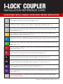
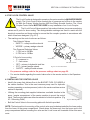
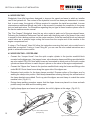
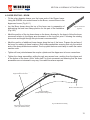
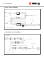
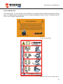
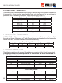
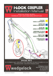
I-LOCK COUPLER TM INSTALLATION MANUAL - v4 SPECIAL NOTE Your new Wedgelock Coupler fitted with the I-LOCK TM Safety Device requires the installation of a third hydraulic line - please follow the instructions carefully NORTH AMERICA Toll-free: 800 CASCADE (227.2233) Telephone: 503-669-6257 [email protected] I-LOCK COUPLER TM INSTALLATION REFERENCE CARD PLEASE READ INSTALL MANUAL THOROUGHLY BEFORE INSTALLATION 1 Remove Bucket if attached to the excavator dipper arm. (8)*. 2 Install Quick Coupler using the carrier machine’s original dipper and linkage pins (8, 9)*. 3 Once mounted, rotate coupler through its full range of movement and check clearances around coupler and dipper arm (9)*. 4 Begin routing hoses from coupler to the dipper manifold on the dipper arm to determine hose routing and dipper manifold positioning (10, 12)*. 5 Position dipper arm hoses, install hose clamps and connect hoses to dipper manifold as labeled (10, 12)*. 6 Position boom hoses, install hose clamps and join unions. Ensure all moving joints are fitted with abrasive sleeve (13)*. 7 After hose routing is completed, it will be easy to determine the best/final mounting location for the coupler control valve (11, 14)*. 8 Route hoses from valve ports to hoses on boom and join with unions (14)*. 9 Locate and connect pressure line from test port on pump to “P” port on valve (14)*. 10 Locate and connect hose from hydraulic tank return line to “T” port on valve (14)*. 11 Locate mounting position for I-LOCK control switch in cab (15)*. 12 Route electrical harness from din connectors on valve to switch harness and attach positive and negative leads (15)*. 13 Check circuit pressures (20)* and test coupler function to ensure system is working properly (refer to Operators Manual) *(Refers to Installation Manual page reference) CONTENTS NORTH AMERICA PAGE REFERENCE CARD 2,3 SECTION 1: INSTALLATION GUIDELINES 1.0 CHECK LIST SECTION 2: PRECAUTIONS 2.0 SAFETY PRECAUTIONS 6 2.1 WELDING PRECAUTIONS 6 3.0 SAFETY DURING COUPLER INSTALLATION 7 3.1 COUPLER ORIENTATION 7 3.2 REMOVING THE EXISTING BUCKET 8 3.3 FITTING THE COUPLER (LINK PIN) 8 3.4 FITTING THE COUPLER (DIPPER PIN) 9 SECTION 3: COUPLER INSTALLATION SECTION 4: HYDRAULIC KIT INSTALLATION 4.0 JUNCTION MANIFOLD POSITION 10 4.1 FITTING THE JUNCTION MANIFOLD BLOCK 10 4.2 THE I-LOCK CONTROL VALVE 11 4.3 INSTALLING THE CONTROL VALVE 11 4.4 HOSE ROUTING 12 4.5 HOSE ROUTING – DIPPER ARM 12 4.6 HOSE ROUTING – BOOM 13 4.7 HOSE ROUTING – BOOM TO VALVE 14 4.8 HOSE ROUTING VALVE TO PUMP / TANK 14 5.0 ELECTRICAL INSTALLATION 15 SECTION 5: ELECTRICAL INSTALLATION SECTION 6: ASSEMBLIES 6.0 LOOSE HOSE KIT ASSEMBLY 16 6.1 PRE-CRIMPED HOSE KIT ASSEMBLY 16 6.2 ELECTRICAL SCHEMATIC 17 7.0 FINISH & TEST 18 8.0 IN CAB DECALS 19 9.0 TORQUE CHART – METRIC BOLTS 20 9.1 TORQUE CHART – JIC CONNECTORS 20 9.2 PRESSURE SETTING CHART 20 SECTION 7: FINISH & TEST SECTION 8: DECALS SECTION 9: TORQUE CHARTS 4 NORTH AMERICA SECTION 1: INSTALLATION GUIDELINES Please read this Installation Manual thoroughly before you commence installation of the I-Lock Coupler. Deviating from these instructions may result in increased install time and / or damage to the hydraulic kit, carrier machine or attachment. 1.0 CHECK LIST Before you start check the following • Check the contents of the installation components supplied. • Ensure that the components are correct for the carrier machine that the coupler is to be installed. • Check that the carrier machine is positioned on level ground. • Check that you have absorbent materials available to soak up any fluid spills. • Dispose of any used materials in a safe and environment friendly manner. • Power off the carrier machine. If the machine has been working ensure that it has cooled down adequately prior to commencing any part of the installation procedure. • Before carrying out any welding on the carrier machine disconnect the battery. Refer to the carrier machine operator / maintenance manual. • Ensure that the pressure in the hydraulic system is relieved before opening any hydraulic lines. 5 SECTION 2: PRECAUTIONS NORTH AMERICA Please ensure you follow the stated precautions below while carrying out the coupler and hydraulic kit installation procedure. 2.0 SAFETY PRECAUTIONS • Always use PPE (Personal Protective Equipment) when servicing, operating or maintaining plant, machinery and its components. • Refer to the carrier machine “Service Manual” for correct procedures when carrying out work on the machine. The machine service manual takes precedence over any discrepancies between that and this installation manual. • Allow for hydraulic oil to cool adequately before opening or accessing any hydraulic lines. Hydraulic lines, fittings and components can be hot which can be harmful causing severe burns. • Relieve the hydraulic tank pressure before accessing hydraulic lines. Refer to the carrier machine service manual for proper procedures. • Ensure that the stick of the carrier machine is resting on the ground at all times – do not leave attachments suspended in the air during service / installation. • Check and tighten all fittings, hose connections and joints within the hydraulic quick coupler circuit prior to activating the machine. • Visually inspect for oil leaks tighten and adjust accordingly. Avoid contact with hydraulic fluids and high pressure oils – use cardboard or similar as a backing when checking for leaks. • Oil spills are sometimes unavoidable. Contain all fluid spills with appropriate absorbent materials and dispose accordingly. Immediately clean affected areas to minimize safety risks. • When operating plant and machinery keep people and property well out of harms way. Evaluate the working environment and identify hazards. Ensure that all people involved in the installation understand the hazards associated with this procedure. 2.1 WELDING PRECAUTIONS • Before commencing any welding procedures on the carrier machine ensure that the engine is turned off and the battery supply is disconnected (refer to the carrier machine service manual). • Ensure all surrounding areas are protected with a flame resistant covering. Clear surrounding areas of combustible materials. Ensure you have a fire extinguisher at hand. • Cover highly susceptible surfaces like cylinder rods, glass windows, electrical components and plastics to prevent spatter or heat damage. • Connect the ground cable (earth lead) from the welder to the component to be welded to the carrier machine. • Ensure parts and surfaces to be welded are clean and prepared properly for welding. • Use appropriate PPE (Personal Protective Equipment) when carrying out any welding procedures. 6 SECTION 1: SAFETY NORTH AMERICA 3.0 SAFETY DURING COUPLER INSTALLATION NORTH AMERICA • Always SECTION 3: COUPLER INSTALLATION use the correct PPE when removing attachments from carrier machines. • Stand well clear of machinery that is in motion at all times. • NEVER place hands or fingers near pin holes or recesses. FIG 3.1.1 Coupler Orientation 3.0 SAFETY DURING COUPLER INSTALLATION • Always use correct tools when carrying out removal and installation of attachments on the carrier • Always use the correct PPE when removing attachments from carrier machines. machine. Stand well clear of machinery that is in motion at all times. • Use correct lifting techniques and lifting equipment when maneuvering heavy objects. NEVER place hands or fingers near pin holes or recesses. • Attachments may tools roll or tip carrying during out removal placed on the groundon– the place with extreme Always use correct when removalwhen and installation of attachments carrier caution. machine. Use correct techniques andinstalling lifting equipment when maneuvering heavypinned objects to the carrier machine. • Always use lifting assistance when and removing attachments Attachments may roll or tip during removal when placed on the ground – place with extreme caution Always useORIENTATION assistance when installing and removing attachments pinned to the carrier machine 3.1 COUPLER 3.1 COUPLER ORIENTATION The I-Lock Coupler has been designed and manufactured to fit the dipper arm and linkage assembly of the carrier machine. The I-Lock Coupler fits the carrier The I-Lock has been only designed to fit thethe dipper arm andview. machine in Coupler one orientation withand themanufactured C-Section facing operators linkage assembly of the carrier machine. The I-Lock Coupler fits the carrier (see fig 3.0.1) machine in one orientation only with the C-Section facing the operators view (see fig 3.0.1) • Always use the original bucket pins to fit the coupler to the machine. These pins are designed for the dipperuse arm linkage assemblies. Always theand original bucket pins to fit the coupler the machine. These pins are designed for the dipper arm and linkage assemblies. • Always replace o-rings to original positions and utilize pin retention systems where applicable. Always replace o’rings to original positions and utilize pin retention systems where applicable. • DO NOT use standard attachment pins to connect the coupler to the machine. If unsure consult DO NOT use standard attachment pins to connect the coupler to the machine. If unsure consult your Wedgelock immediately. your Wedgelock Dealer Dealer immediately. a THUMBisis// will will be thethe carrier machine utilizing the main dipper position refer to the refer to • If aIfTHUMB befitted fittedtoto carrier machine utilizing the mainpindipper pin position THUMB Installation Guide for reference. the THUMB Installation Guide for reference. Dipper Arm (Operator View) Coupler C-Section Coupler C-Section Fig 3.1.1 Orientation Fig Coupler 3.1.1 Coupler Orientation Page 6 7 SECTION 3: COUPLER INSTALLATION NORTH AMERICA SECTION 3: COUPLER INSTALLATION NORTH AMERICA 3.2 REMOVE THE EXISTING BUCKET 3.2 REMOVE THE EXISTING BUCKET • Before you fit the coupler to the carrier machine you have to firstyou remove any existing attachment from dipper • Before fit the coupler to the carrier machine youthe have arm. (Figremove 3.2.1) any existing attachment from the dipper to firstly arm. (Fig 3.2.1) • Place the bucket or attachment in a safe position on the Place the bucket or attachment in a safe position on the ground. ground. • Undo the pin retention systems holding the dipper pin and Undo the pin retention systems holding the dipper pin and link pin pininintheir theirposition. position. link • Gentle Gentle raise raisethe thebucket bucket ground rotate off off thethe ground and and crowd the the cylinder until the weight is off the dipper pin. cylinder until the weight is off the dipper pin. pinpin and place in ainclean area.area. • Remove Removethe thedipper dipper and place a clean the ground ground with with the the bucket crowd cylinder • Lower Lower the the bucket bucket to to the curl cylinder until there is no longer weight on the link pin. until there is no longer weight on the link pin. and place in ainclean place • Remove Removethe thelink linkpin pin and place a clean place. Fig 3.2.1 Remove Bucket 3.3 FITTING THE COUPLER (Link Pin) 3.3 FITTING THE COUPLER (Link Pin) • Ensure the coupler is sitting on a flat surface in the correct • Ensure the coupler is sitting on a flat surface in the correct orientation. orientation. Align the dipper arm of the carrier machine with the • coupler. Align the dipper arm of the carrier machine with the coupler. forfor thethe linkage boss assembly on the • Position Positionthe theo’rings o-rings linkage boss assembly on the linkage linkageboss boss(if(iffitted). fitted). cylinder lower the linkage into position on • Using Usingthe thecrowd bucket curl cylinder lower the linkage into position the rear boss of the coupler (Fig 3.3.1) on the rear boss of the coupler (Fig 3.3.1). Align the coupler if necessary using a bar or lever. • Align the coupler if necessary using a bar or lever. Insert the linkage pin through the coupler boss and • linkage Insert the linkage pin through the coupler boss and linkage boss. boss. Align pin retention system and fix linkage pin into place. • Locate Align pin system and position fix linkage pin into place. theretention o’rings into the correct (if fitted). • NOTE Locate –theORIGINAL o-rings into the correct position fitted). OEM LINKAGE PIN (if MUST BE USED. • NOTE – ORIGINAL OEM LINKAGE PIN MUST BE USED. Fig 3.3.1 Lower linkage into coupler 8 Page 7 SECTION 3: COUPLER INSTALLATION NORTH AMERICA NORTH AMERICA SECTION 3: COUPLER INSTALLATION 3.4 FITTING THE COUPLER (Dipper Pin) 3.4 FITTING THE COUPLER (Dipper Place o’rings over ear plates of couplerPin) to hold in position until ready for final placement. • Carefully Place o-rings ear plates of the coupler hold in position untilweight readyofforthe final placement. raise over the dipper arm of carriertomachine so that the coupler is off the ground. Ensure that the dipper arm is in a vertical position. (Fig 3.4.1). • Carefully raise the dipper arm of the carrier machine so that the weight of the coupler is off the ground.the Ensure the dipper is in a vertical Retract crowdthat cylinder until thearm coupler front boss position. aligns with(Fig the3.4.1). dipper pin hole. The coupler will balance allowing an easy insertion of the main dipper pin. • Retract the bucket curl cylinder until the coupler front boss aligns with the dipper pin hole. The coupler balance allowing easypin insertion of the main dipper pin. Align pin will retention system and fixandipper into place. • Align pin retention system and fix dipper pin into place. Grease both the dipper pin and the linkage pin. • Grease both the dipper pin and the linkage pin. Crowd coupler through full rotation to check clearances. • Rotate coupler through full rotation to check clearances. NOTE – ORIGINAL OEM DIPPER PIN MUST BE USED. • NOTE – ORIGINAL OEM DIPPER PIN MUST BE USED. Fig 3.4.1 Raise dipper arm to Fig 3.4.1 Raise dipper arm to take weight off coupler take weight off coupler Fig 3.4.2 Retract bucket curl cylinder Fig 3.4.2 Retract crowd cylinder to align dipper pin to align dipper pin CAREFULLY ROTATE THE COUPLER THROUGH FULL ROTATION CAREFULLY CROWD THE COUPLER THROUGH FULL ROTATION TO CHECKTO CLEARANCES CHECK CLEARANCES IFIFTHERE ARE ANY SIGNS OF OF INTERFERENCE STOPSTOP IMMEDIATELY AND AND THERE ARE ANY SIGNS INTERFERENCE IMMEDIATELY CONTACT YOUR WEDGELOCK DEALER CONTACT YOUR WEDGELOCK DEALER Page 8 9 SECTION 4: HYDRAULIC KIT INSTALLATION NORTH AMERICA SECTION 4: HYDRAULIC KIT INSTALLATION There are three main NORTHsections AMERICA to the hydraulic kit installation which consists of: • Fitting of the Junction Manifold Block to the dipper arm. There are three main sections to the hydraulic kit installation which consists of: • Fitting of the I-Lock Control Valve in the engine/pump compartment. • Routing the 3 Line Hydraulic Circuit to complete the hydraulic part of the coupler installation. • FittingoftheJunctionManifoldBlocktothedipperarm. • FittingoftheI-LockControlValveintheenginecompartment. 4.0 JUNCTION MANIFOLD POSITION • Routingthe3LineHydraulicCircuittocompletethehydraulicpartofthecouplerinstallation. The Junction Manifold block is a 9 port block designed to enable multiple JUNCTION MANIFOLD POSITION routing4.0 options and variable positional options to optimize the jumper hose routing at the base of the dipper arm. Note correct orientation. The Junction Manifold block is a 9 port block designed to enable (Fig 4.0.1) Fig 4.0.1 Junction Manifold Block This side to dipper arm (Correct orientation) multiple routing options and variable positional options to optimize the jumper hose routing at the base of the dipper arm. Note correct orientation. (Fig 4.0.1) • Positioning of the Junction Manifold Block and the Fig 4.0.1 Junction Manifold Block hose routing option is critical to the life cycle of the jumper hoses. (Fig 4.0.2) • Positioning of the Junction Manifold Block and the hose routing option is critical to the life cycle of the jumper (FigManifold 4.0.2) • To determine the optimum position of thehoses. Junction Block first rotate the bucket curl cylinder through full rotation to check Fig 4.0.2 Hose routing options available clearances for the manifold at both full stroke and zero stroke. Fig 4.0.2 Hose routing options • To determine the optimum position of the Junction Manifold Block firstly rotate the crowd cylinder • The manifold be placed as close as possible to for thethe main dipperatpin to minimize throughshould full rotation to check available clearances manifold both full stroke jumper and zero hose length stroke.– when utilizing universal jumper hose kits any excess jumper hose can be then contained inside the coupler body. • The manifold should be placed as close as possible to the main dipper pin to minimize jumper hose – when MANIFOLD utilizing universal jumper hose kits any excess jumper hose can be then 4.1 FITTING THElength JUNCTION BLOCK contained inside the coupler body. • Once the optimum position has been determined, clean and prepare the surface of the dipper 4.1 FITTING THE JUNCTION MANIFOLD BLOCK arm to be welded. • Once the optimum position has been determined, clean and prepare the surface of the dipper arm • Lightly tack manifold into position, carefully tacking only the ends of the manifold. (Refer to to bethe welded. welding precautions and carrier machine service manual for welding instructions). • Lightly tack the manifold into position, carefully tacking only the ends of the manifold. (Refer to welding precautions and carrier service manual welding • Fit one adaptor to the manifold and machine route one jumper hoseforfrom the instructions) manifold to the coupler cylinder. • Fit one adaptor to the manifold and rout one jumper hose from the manifold to the coupler cylinder. • Rotate coupler SLOWLY through full rotation checking that • Crowd couplerfreely SLOWLY full rotation checkingor that the hose can move freely and is not the hose can move and through is not subject to pinching pinching or crushing at any point. Re-position manifold if required. crushingsubject at anytopoint. Re-position manifold if required. • Remove jumper hose, stitch weld the ends ONLY of the • Remove jumper hose, stitch weld the ends ONLY of the manifold block to the dipper arm. (Fig 4.1.1 Stitch weld location) manifold block to the dipper arm. (Fig 4.1.1 Stitch weld • Touch up paint finish on welded component to match location) carrier machine colour Weld here on both ends Weld here on both ends • Touch up paint finish on welded component to match carrier Weld here on both ends machine color. 10 Fig 4.1.1 Stitch weld location Fig 4.1.1 Stitch weld location NORTH AMERICA SECTION 4: HYDRAULIC KIT INSTALLATION 4.2 THE I-LOCK CONTROL VALVE The I-Lock Coupler is designed to operate on the carrier machine’s MAINS PRESSURE supply. The I-Lock Control Valve controls the oil pressure and oil flow to the coupler for both the Primary Wedge function AND the Safety Knuckle function. The I-Lock Coupler Control Valve MUST BE USED for any installation of an I-Lock Coupler. • The I-Lock Control Valve consists of twin solenoid valves, two pressure reducing valves and 5 ports for hose routing. The distinguishable markings are there to assist with the electrical connection and hose routing to ensure that the coupler operates in accordance with which it has been designed. (Fig 4.2.1) • The markings on the control valve are as follows. Twin Solenoid Valves • SAFETY – safety knuckle solenoid. • WEDGE – primary wedge solenoid. Twin Solenoids Two Pressure Reducing Valves • 1. PRV set to 240 Bar • 2. PRV set to 145 Bar 5 Ports for hose routing • P – pressure in. • T – tank return. • RET – primary to hydraulic tank line. • EXT – primary wedge extend. • SAFETY – safety knuckle release. Check Valve PRV set to 145 Bar PRV set to 240 Bar Fig 4.2.1 I-Lock Control Valve • For pressure settings refer to the pressure settings chart on page 20. • For service details regarding the control valve refer to the service section in the Operators Manual. 4.3 INSTALLING THE CONTROL VALVE • Identify the pump that delivers flow to the BUCKET CURL CYLINDER of the carrier machine. This is the most common pump used for hydraulic couplers operating on mains pressure (refer to the carrier machine service manual if required). • Utilizing the mounting plate supplied determine a suitable location in the pump / engine compartment of the carrier machine to mount the control valve. The mounting plate can either be welded or bolted into position. (Fig 4.3.1 Mounting Plate) Fig 4.3.1 Mounting Plate • Bolt the Control Valve to the mounting plate with the bolts provided. NOTE: The best position for mounting of the control valve may be determined after the hose routing from the boom to the pump compartment. Check where the hoses exit from the boom end in the pump compartment before mounting the valve as the I-Lock hoses will invariable follow this same route. 11 SECTION 4: HYDRAULIC KIT INSTALLATION NORTH AMERICA 4.4 HOSE ROUTING Wedgelock Hose Kits have been designed to improve the speed and ease in which an installer can fit the hydraulic kit. The content of the hydraulic hose kit has been pre determined to ensure that, in most cases, the majority of fittings required to complete the install are provided. In some circumstances additional fittings may have to be sourced to complete the connection to the pump test port and tank return. For information regarding the port type at these locations please refer to the carrier machine service manual. The “Pre-Crimped” Wedgelock hose kits are color coded at each end of the pre-crimped hoses. Following the Installation Reference Card will assist with identifying each of the hoses to be routed in respect to their relative positions on the carrier machine. Once the manifold block and solenoid control valve are in position begin routing the hoses from the coupler end of the machine to the engine compartment end. If using a “Pre-Crimped” Hose Kit follow the instructions ensuring that each color coded hose is positioned as required. If using a ‘Lose Fitting Kit” you can use the color coded instructions as a guide to achieve the same results. 4.5 HOSE ROUTING – DIPPER ARM • Connect the “Jumper Hoses” from the quick coupler cylinder to the junction manifold block mounted on the dipper arm. Use jumper hoses, nylon abrasion sleeve and fittings provided which are color coded YELLOW. Note which hoses are connected to which ports on the quick coupler cylinder as these will have to match the port options on the valve in the engine compartment. • Connect the “Dipper Arm” hoses to the junction manifold block using the hoses and fittings color coded BLUE. Route these hoses along the upper side of the dipper arm. • Determine best position for the hose clamps provided. Prepare surface of the dipper arm for welding the clamps into position. Weld clamp assemblies ensuring that only the vertical ends of the clamp brackets are welded. Touch up paint the dipper arm and clamp to match the carrier machine color. (Fig 4.5.1) • During clamp welding procedure ensure that the dipper hoses are placed in a clean and safe position away from heat and the welding area. • Lightly clamp dipper arm hoses into position, do not fully tighten at this stage. (Fig 4.5.2) Clamps HoseHose Clamps 12 Fig 4.5.1 Hose Clamp Position (example only) Fig 4.5.2 Hose Clamp Assembly SECTION 4: HYDRAULIC KIT INSTALLATION NORTH AMERICA 4.6 HOSE ROUTING – BOOM • Fit the nylon abrasive sleeve over the loose ends of the Dipper hoses. Using the GREEN color coded hoses for the Boom, connect these to the dipper arm hoses. (Fig 4.6.1) • Lay the Boom hoses along the top of the boom arm in preparation of determining the best hose clamp position for this part of the installation. (Fig 4.6.2) Fig 4.6.1 Hose Joint (Typical) • Mark the position of the top hose clamp on the boom, allowing for the hose to follow the boom movement relative to the dipper arm movement on the top pivot point. Following the existing hose route and length through this pivot area is recommended. • Mark the position of additional hose clamps along the top of the boom. Prepare the surface of the boom for welding in these locations. Weld clamp assemblies ensuring that only the vertical ends of the clamp brackets are welded. Touch up paint the boom and clamp to match the carrier machine color. • Tighten all hose joints between the coupler cylinder and the dipper arm to boom connections. • Tighten the clamp assemblies, pulling through any excess hose, working from the dipper end to the bottom of the boom. Allow “hose slack” for pivot movement and ensuring that the hose assemblies are not stressed in any way. Use cable ties where required. Dipper to Boom Hose Dipper to Joint Boom Hose Joint Boom to Hose Joint Boom to Valve ClampClamp Assemblies Assemblies (Multiple locations along boom) (Multiple locations along boom) Valve Hose Joint Fig 4.6.2 Boom Hose Routing Hose slack for Hose slack for pivot movement (with nylon abrasive sleeve) pivot movement (with nylon abrasive sleeve) 13 SECTION 4: HYDRAULIC KIT INSTALLATION NORTH AMERICA 4.7 HOSE ROUTING – BOOM TO VALVE • Connect the RED color coded hoses for the Boom to Valve to the boom hoses at the base end of the boom. • Route the hoses through to the pump compartment towards the control valve following the existing hose routing from the boom end. • Trace the hoses from the quick coupler cylinder right through to the end where they connect to the valve to determine the correct hose for each port position on the valve. • Connect the hose ends to the control valve ensuring that they are connected to their respective port positions relative to the cylinder. • Cable tie Boom to Valve hoses to existing hoses where appropriate and coil any excess hose in the pump compartment. Ensure that the hoses are not bound up or under any strain. • Tighten all hose joints and fittings between the lower boom end and the control valve. 4.8 HOSE ROUTING – VALVE TO PUMP / TANK • Using the BLACK color coded hoses from the install kit connect the hose ends to the valve marked P (Pump) and T (Tank). • The supplied Check Valve should be connected directly to the “P” (Pressure) port on the I-Lock Control Valve with the fittings provided in the kit. (See Control Valve Assy Fig 4.2.1) • Utilizing a “TEST PORT” on the pump that delivers hydraulic pressure to the bucket curl cylinder circuit (see 4.3 above) connect the hose from the check valve on the “P” port to the test port. • Locate an existing tank line hose on the main return manifold or hydraulic tank. Disconnect the existing hose and install a tee fitting. • Reinstall the existing hose onto one end of the tee and then connect the new tank line hose from the control valve “T” port to the other end of the tee. • Cable tie hoses to existing hoses where appropriate and coil any excess hose if required. Ensure that the hoses are not bound up or under any strain. • Tighten all hose joints and fittings between the control valve and the pump and tank. NOTE 1: When utilizing a “Pre-Crimped” or “Loose” hose kit supplied by Wedgelock we have endeavored to supply the majority of the fittings required to carry out a complete install of an I-Lock Coupler, however due to the vast array of different carrier machines, fitting types and port sizes, not all circumstances may be accounted for. In instances where the fittings supplied do not match the port size or the type of carrier machine that this install is being carried out on please contact your nearest machinery dealer or hydraulic fittings provider for the additional appropriate component(s). NOTE 2: See Hydraulic Schematic (Fig 6.0.1) 14 SECTION 5: ELECTRICAL INSTALLATION NORTH AMERICA 5.0 ELECTRICAL INSTALLATION The I-Lock Coupler must be operated utilizing the I-LOCK CONTROLLER, DUAL SWITCH ASSEMBLY and SOLENOID LOOM. The proprietary electrical components have been designed in conjunction with the functionality and operation of the coupler safety features. The built in “Timer” and “Operational Sequences” controlling the solenoid valves are features which provide the operator and fellow co-workers a safe work environment during attachment change over. Failure to utilize the proprietary electrical components with the I-Lock Coupler could result in coupler malfunction, causing serious harm or even death. (Fig 5.0.1 & 5.0.2 & 5.0.3) Fig 5.0.1 Dual Switch Assembly Fig 5.0.2 I-Lock Controller Fig 5.0.3 Solenoid Loom The I-Lock Controller, Dual Switch Assembly and Solenoid Loom are designed to enable a “plug & play” electrical installation process. • Determine a suitable position for the I-Lock Controller. Ensure the position is a dry location and easily accessible. Mount into position. (Caution - Do not over tighten fixing screws) • Find two spare locations in the machine console, preferably side by side, to insert the dual rocker switches. • Route the switch wires to the I-Lock Controller. Connect the corresponding male spade fitting to the female connector on each of the assemblies. • Locate a switched (fused) power source from within the console of the carrier machine. Connect the RED power lead on the Dual Switch Assembly to the power source. • Find a suitable earth location (negative) and connect the BLACK wire from the I-Lock Controller. • Plug the Solenoid Loom into the I-Lock Controller. • Route the Solenoid Loom from the I-Lock Controller position through to the engine compartment where the I-Lock Solenoid Valve is located. • Connect the RED labeled DIN Plug to the “WEDGE” solenoid. • Connect the BLACK labeled DIN Plug to the “SAFETY” solenoid. • Ensure that all electrical looms are routed and fixed securely using cable ties where required. • NOTE: See Electrical Assembly (Fig 6.2.2) 15 SECTION 6: ASSEMBLIES 6.0 LOOSE HOSE KIT ASSEMBLY Fig 6.0.1 Loose Hose Kit Assembly 6.1 PRE-CRIMPED HOSE KIT ASSEMBLY Fig 6.1.1 Pre-crimped Hose Kit Assembly 16 NORTH AMERICA SECTION 6: ASSEMBLIES NORTH AMERICA 6.2 ELECTRICAL ASSEMBLY I-Lock Controller Solenoid Loom Male / Female Connectors Dual Switches Earth Connection Power Source Connection Din Plugs Fig 6.2.2 Electrical Assembly 17 SECTION 7: FINISH & TEST NORTH AMERICA 7.0 FINISH & TEST Before starting this section, position the machine in the “Oil Level Check” position as suggested by the excavator machine manufacturer. Check the oil level sight gauge on the hydraulic tank. Add hydraulic oil if necessary (refer to the carrier machine service manual for further information). • Check the hose clamp assemblies and valve mounting bolts are tightened as per the Torque Setting of Metric Bolts & Nuts Chart (Fig 8.0.1) • Starting at the coupler end thoroughly check that the hose connections are tightened through out the complete circuit as per the JIC (SAE 37º FLARE) Connection Chart (Fig 8.1.1). • Clear all personnel and all obstacles from the swing radius area and working parameter of the machine. • From the seat of the excavator, start the machine and lower the excavator arm to near the ground. In a very slow motion, using the excavator levers, raise the dipper arm and rotate the coupler through full rotation. Then raise the boom of the excavator and motion the dipper arm cylinder to full extension. Now motion the dipper arm cylinder to full retraction, lowering the boom arm in unison. Use this process to check the hose routing throughout the complete circuit. Ensure that the hoses are not under any strain or subject to potential jamming or pinching. Assistance will be required to do this. Modify hose routing if required. • Running the machine at idle or a low engine RPM setting to supply a low volume of oil through the circuit. Activate the circuit and check for any leaks. Shut down the machine immediately if leaks are detected, then tighten coupler as required and re-check. • Activate the coupler circuit several times to ensure that the system is working correctly – refer to the I-Lock Coupler Operators Manual. • Once the test procedure has been completed, touch up paint any welded brackets or assemblies and cable tie any loose hoses. • Affix “In Cab” Decals in a suitable location within the operators working area. (Fig 7.0.1 In Cab Decals) Before using the I-Lock Coupler carefully read the I-Lock Coupler Operators Manual thoroughly. 18 SECTION 8: IN CAB DECALS NORTH AMERICA 8.0 IN CAB DECALS The following two “In Cab” Decals must be affixed in a suitable location within the operators working area. For replacement decals please call your nearest Wedgelock dealer. (Fig 8.0.1 Warning Decal & 8.0.2 I-Lock Coupler Oerating Decal) Fig 8.0.1 Warning Decal Fig 8.0.2 I-Lock Coupler Operation Decal 19 SECTION 9: TORQUE CHARTS NORTH AMERICA 9.0 TORQUE CHART – METRIC BOLTS The following chart gives the standard torque setting of the bolts used in this hydraulic kit installation. It is important to follow the chart when installing bolts and nuts. Failure to do so could result in premature failure, damage to components, or even serious injury. (Fig 8.0.1) Torque Setting of Metric Grade 8.8 Bolts & Nuts Bolt Dia x Pitch (mm) Nm Lb.Ft M6 x 1.0 9.9 7.3 M8 x 1.25 24.0 17.7 M10 x 1.5 48.0 35.4 M12 x 1.75 83.0 61.2 M14 x 2.0 132.0 97.3 M16 x 2.0 200.0 147.4 M18 x 2.5 275.00 202.7 M20 x 2.5 390.0 287.4 Note: 1Nm = 0.102kgm = 0.737 lb.ft Fig 8.0.1 Torque Setting of Metric Grade 8.8 Bolts & Nuts 9.1 TORQUE CHART – JIC CONNECTIONS JIC (SAE 37º Flare) Connections are a very common connection in fluid power applications. Both the male and female fittings have a 37º seat. The seal takes place between the male flare and the female cone seat. The thread holds the connection mechanically. Nominal Size 1/4” 3/8” 1/2” Torque Setting of JIC Connectors Dash Size Nm Lb.Ft -4 15 - 17 10.8 - 12.5 -6 27 - 30 19.6 - 22.0 -8 59 - 65 45.5 - 47.8 F.F.F.T. 2 1 1/4 1 Fig 8.1.1 JIC Connections Chart 9.2 PRESSURE SETTING CHART The following chart shows the range of allowable pressure settings for the I-Lock Coupler circuit. It is highly recommended that the pressures for each function are tested and checked before the equipment is put to use. I-Lock Control Valve Marking Function P Pressure In Pressure Range (bar) Full Mains Pressure Range (psi) T Tank return N/A RET Retract Primary Wedge 225-240 3260-3580 EXT Extend Primary Wedge 138-145 2000-2100 SAFETY Safety Knuckle Release 225-240 3260-3580 Marking Function Pressure Range (bar) Pressure Range (psi) RET Retract Primary Wedge 225-240 3260-3580 EXT Extend Primary Wedge 138-145 2000-2100 SAFETY Safety Knuckle Release 225-240 3260-3580 Pressure Relief Valve 166-180 2400-2600 I-Lock Primary Cylinder 20 NORTH AMERICA PO Box 20187 • Portland, OR 97294-0187 • USA • 800 CASCADE (227.2233) • Tel 503.669.6257 • www.wedgelockusa.com Cascade and Wedgelock are registered trademarks of Cascade Corporation. © Cascade Corporation 2013. All rights reserved. (902-0015 Rev 2) Form 6827658 500 GE 06/13