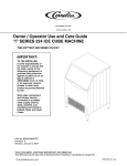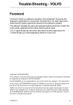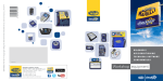
1
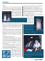
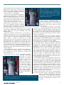
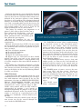
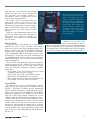
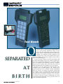
Test Bench
O
Separated
Separated
at
at
Biirt
rth
h
B
April 1998
ver the years, I have had the opportunity to
use a great many diagnostic tools at my
garage, the Lusty Wrench. A few of these have
been “loaners” from manufacturers who were
looking for feedback and/or publicity. But
along the way, I have also parted with a great
deal of my hard-earned cash to acquire some of these
tools for continuing use.
A year or two ago, I formed a small consortium with
two other small shops in the area, and we jointly purchased an Autodiagnos Multi-Tester plus along with a
host of adapters and memory cassettes. Regular
Import Service readers may recall that this tool has
figured prominently in a number of recent articles.
Because it can be plugged in between the car’s
computer and its wiring harness, the Multi-Tester
plus has proven to be a valuable tool for identifying
faults in sensors or wiring. Its parallel connection
also allows access to current data on each pin and
has a built-in fault tracing function which can identify many types of failures. In many cases, of course,
its greatest value has been in eliminating the fuel
system from consideration as the possible source of
some driveability problem.
29
Test Bench
adapter. Two sets of Multitester plus parallel connection adapter harnesses and memory cassettes are
shown at the bottom left corner of this page.
With this connection it is possible to diagnose
internal ECU failures, power feed problems, ground
faults, and faults in sensors and wiring. For a thorough description of the parallel connection capabilities of the Multi-Tester plus, refer to the August
1995 issue of Import Service.
On most 1989-95 Volvo models, it is also possible
to troubleshoot using the parallel connection, while
also utilizing the six-pin
DLC to retrieve
fault
codes.
This photo shows the diagnostic twins at work,
Most
1995
and
with both hooked up to the same car. Most Volvo
later
Volvos
are
dealer techs tape the ON/OFF switchbox and
equipped
with
adapter to the bottom of the VST (or Multi-Tester
a 16-pin data
plus) body to make it easier to work with.
link connector.
By adding the
home of the annual International Twins Festival, on
my way to visit Volvo of Hudson. There, I met with
Some ’96 and ’97 models experiVolvo Master Technician Dan Radford, who had
enced problems with this system
kindly agreed to give us a tour of the VST’s capabilsetting a DTC and illuminating
ities and let us see how the Multi-Tester plus comthe MIL. The freeze-frame data
pared to it.
associated with the code showed
Autodiagnos kindly lent us a set of cables and
this problem happening at low
memory cassettes that allowed our familiar Multiengine temperatures. The probTester plus not merely to emulate, but to actually
lem was traced to the purge
become the Volvo Scan Tool. It turns out that the
valves sticking when first activated after a cold start, and a new
Autodiagnos folks make both the VST and the
part was introduced to correct the problem.
Multi-Tester plus to the same specs and with the
same internal circuitry. The differences are merely
cosmetic.
Twins?
Some time ago, I heard via the grapevine that our
Multi-Tester plus was not just what it appeared to
be, but was, in fact, the identical twin of the Volvo
Scan Tool, from which it had been separated at birth.
I had also heard that the
VST, as it is known, is the
favored weapon of Volvo
dealer techs everywhere.
So it seemed appropriate
that I should travel
through Twinsburg, Ohio,
Twins Make It More Exciting
With the proper adapters and cassettes, the MultiTester plus can be used for diagnostic troubleshooting on Volvo cars in three different ways. They are:
➤ Parallel connection at the ECU for engine management systems such as LH-Jetronic 2.0-2.2, LHJetronic 2.4, Regina, and Motronic 1.8 for many
Volvo models.
➤ A combination of connection at the ECU and
the six-pin underhood diagnostic link connector
(DLC) on 1989 and later model year Volvos for the
systems noted above, plus Motronic 3.2.
➤ At the 16-pin OBD II console DLC for most 1995
and later Volvos with Motronic 4.3, 4.4, and Fenix 5.2
engine management systems.
Each connection option
has a unique set of characteristics. The parallel connection, which is available
for most European makes,
requires accessing the ECU
wiring harness connector
to install a double-sided
32
Volvo is currently having some problems with SAS valves not
seating in the fully closed position due to a sticking diaphragm.
If we had simply applied vacuum to the SAS control valve with a
vacuum pump while the engine was running, we would have set
a DTC in memory, but since we did it via the tester, we didn’t
have to worry about that.
April 1998
serial communications components, the
Multi-Tester plus offers 100 percent
dealer-level troubleshooting ability, as
well as diagnostic trouble code (DTC)
retrieval and reset capabilities.
This set-up goes beyond the federallymandated requirements of OBD-II by
offering bi-directional control, as well as
access to climate control systems, instrument panels, and various body systems,
such as sunroofs and power seats.
We began our session at Volvo of
Hudson with a brand-new ’98 S70—a
2.4 L, five-cylinder, 20-valve normally
aspirated sedan. The OBD-II connector
is located under a small access cover in
the center console. We hooked up the tester and
selected the appropriate model from the opening
menu. Then we selected ENGINE and then
MOTRONIC 4.4.
Dan had already warmed the car up prior to
pulling it into the bays, so we were able to go right
to work. We decided to run a test of the EVAP system, accessing it from the DIAGNOSTIC CHECK
menu. After a couple of minutes the tester
announced that the test had been completed. Did
this mean that the car had passed the test? No,
explained Dan, we would have to exit back out to
the DTC menu, then check to see whether there was
a code. The absence of a code coupled with the message that the test was completed meant that the test
had been passed. Otherwise there would be a DTC in
current memory.
We verified the absence of DTCs and returned to
the functional test menu, whence we could check
the secondary air system (SAS) by activating the
SAS control valve.
Many DTCs can be logged in pending memory
without triggering
the MIL. If a malfunction is detected
in three consecutive
drive cycles, the
MIL will illuminate.
If it fails to reappear
in three drive cycles,
it will be purged
from memory. You
can access the current status of pending and logged DTCs
under the Read DTCs
menu.
After clearing that code and resetting
adaptive memory, we unplugged an
injector. Because this was a dead misfire, the PCM immediately set a cylinder-specific DTC and fired up the MIL.
A portion of the freeze-frame data is
displayed in this photo.
The message “CNT.MIL OFF= 3”
means the MIL will be extinguished if
the fault referenced is not detected
during the next three warm up and
drive cycles.
We decided to induce a few problems. First we unplugged and then reconnected the
air flow sensor, setting DTC P0201. We were pleased
to see that the tester readout showed the problem as
intermittent. The MIL remained off, since the problem had not recurred and had not (yet) had a serious
impact on emissions.
After clearing that code and resetting adaptive
memory, we unplugged an injector. Because this was
a dead misfire, the PCM immediately set a cylinderspecific DTC and fired up the MIL. A portion of the
freeze-frame data is displayed in this photo.
Pushing the Left Arrow [<—] key while monitoring serial data adds a “parameter number” to the left
margin of the readout. This parameter number corresponds to a specific numbered section of the
appropriate vehicle service manual. For example, a
line number of “10” refers to short-term fuel trim.
The service manual notes the available range (01.992) and the normal value (oscillates around 1).
The significance of variations from the norm are
noted (e.g. values <1 indicate rich air/fuel mixture,
values >1 indicate a lean mixture). There is also a
brief explanation of the meaning and operating strategy underlying each parameter.
I asked Dan to share a tech-tip with us. Here’s one
of the stories he told us: Sometimes the diagnostics
can throw you for a loop. On some late-model
Volvos, proximity to the heat of the exhaust may
cause the front O2 sensor’s insulation to melt. The air
space between the filaments of the conductor and its
insulation is the breathing tube for the O2 sensor.
The melting closes off the supply of outside air upon
which the sensor depends in order to generate an
accurate reading of the difference in the O2 concentrations on each side of the sensor.
Sensor voltage drops, since the O2 concentrations
on each side of the sensor’s tip equalize. The PCM
will respond by enriching the mixture.
The rear O2 sensor will detect the fault
The message “CNT.MIL OFF= 3” means
and will trigger the MIL. The PCM will
the MIL will be extinguished if the fault referenced is not detected during the
default to a limp-home strategy. So far,
next three warm up and drive cycles.
so good.
April 1998
33
Test Bench
Replacing the front O2 sensor should fix the problem, but the MIL will illuminate and throw a DTC on
your test drive because the high sulfur content accumulated in the converter confuses it into thinking
that there is still a problem. The solution is about ten
minutes of sustained driving at high RPM and moderate load, say maybe third gear on the freeway. Be
sure to clear all the DTCs and the adaptive memory
and perform another drive cycle to verify the fix
before returning the car to your customer.
This brings up another very important set of
points. I don’t want to dwell on this, but it
bears widespread distribution: a scan tool
does not fix a car; a good technician does.
When confronted with a driveability probThe Combi menu also provides a functional test of the instrument panel
lem, follow this prescription:
electronics, allowing silly readings like those in this photo.
❶ Verify the complaint. Be sure you
understand what it is that your customer is
experiencing.
The ELECTRICAL menu allows troubleshooting
❷ Read, record, and clear all DTCs. Be sure to note
the anti-theft system or the instrument panel,
any freeze-frame data so that you can try to recreate
referred to as the “Combi.” There are interesting
the conditions under which the problem has previoptions available for the Combi, including resetting
ously occurred.
the default service intervals for vehicles used in
❸ Clear all adaptive memory.
severe service, for example. You can also alter the
❹ Re-verify the condition.
amount of fuel remaining in the tank when the “Low
❺ Re-check for DTCs.
Fuel” lamp first illuminates. (Factory default for this
❻ Repair the underlying cause(s).
parameter is 0.5 gal. You can increase it to as much
❼ Repeat steps 2-5. Your final test drive should
as 2.5 gal. for those of your customers who might
include low-speed, stop and go city driving and
benefit from the change.)
high-speed sustained cruise. A fifteen-minute loop
The TRANSMISSION menu accesses shaft and
is usually enough to allow most OBD-II monitors to
turbine speeds, etc. Dan says he’s had virtually no
activate.
problems with the trannies or the control units on
The number one complaint of motorists is having
the newer Volvos he’s been servicing. You and I may
to take the car back a second time for the same probneed all the info we can get a few years down the
lem. Dan has raised his dealership’s service quality
road.
rating to the highest in the area by adhering faithfulThe BRAKES menu, of course, accesses the antily to this set of rules.
lock system, DTCs, and data stream. Watch out
when reading wheel speeds on a road test. Trees
Other Functions
seem to be inordinately attracted to the front of a car
I mentioned that when equipped with the serial
whose driver is looking elsewhere. There are also
communications kit the Multi-Tester plus can interfunctional actuation
face with numerous other systems in the car. The
tests for the ABS
main menu selections are SERVICE, ENGINE, ELECvalves.
TRICAL, TRANSMISSION, BRAKES, and BODY.
The BODY menu
The first of these, SERVICE, is used to access and
allows communicaextinguish the service required lamp or SRL.
Unlike earlier models where the SRL could be
extinguished by pushing a reset button or
through manipulating the jumper at the six-pin
With the serial communications
underhood diagnostic socket, late model Volvos
kit, you can use the Multi-Tester
require a scan tool or a specialized reset tool
plus to diagnose a bad power seat
capable of a “handshake” with the PCM to reset
switch, for example, by actuating
the SRL.
each seat motor in turn through
In addition to the fuel control system, the ignithe test menu.
tion system can also be entered through the
tester under the ENGINE menu.
34
April 1998
tion with the seats, sunroof, and climate
control systems. You can read high-side
A/C pressures, for instance, which is a
good thing as there is no high-side service
port on most current models.
We found a DTC in memory when we
accessed the power seats on our test car.
Apparently it is an artifact left over from
the factory programming. It proved impossible to clear from memory, but, considering its content, we weren’t going to worry
about it!
With the serial communications kit, you
can use the Multi-Tester plus to diagnose a
bad power seat switch, for example, by
actuating each seat motor in turn through
the test menu.
How To Get It
If you want to get your hands on an Autodiagnos
Multi-Tester plus, or the cartridges and adapter
cables necessary to add serial communications capabilities, contact your local Autodiagnos distributor,
telephone the Autodiagnos U.S. office at (330) 6681518, or Circle No. 201 on the Reader Service Card.
Autodiagnos can provide you with information on
any combination of adapters and cassettes for Volvo
and other European cars, as well as serial communication components.
To get the most out of the powertrain management
diagnostic power of the Multi-Tester plus and the
serial communications kit, you may want to purchase the following diagnostic reference material
from Volvo:
• TP 2310201 is the VST manual and covers serial
communication and text read-out.
• TP 32379/2 covers LH 3.2 and EZK systems.
• TP 2301202 is the Motronic 4.3 reference.
• TP 2318201 and TP 2327201 cover Motronic 4.4.
• TP 2310201 covers the Volvo Scan Tool.
This photo shows the VADIS console with one of the twins in attendance in the upper right. In the
upper left is a built-in breakout box.
Pre-configured screens and dedicated cables let VADIS communicate
with the VST. The technician can
measure a variety of signals using
the built-in leads and pre-configured meter screens through the
breakout box without ever reaching
for his multimeter.
Suffice it to say that, compared to the hurricane that is
this new technology, most of the revolutions in automotive technology of the past thirty years will look
as insignificant as the morning dew. We’ll be updating you later so you can survive the coming storm. ▲
—By Sam Bell
Crystal Balls
We asked Dan to tell us what might be coming
from Volvo in the near future. He introduced us to
VADIS, a PC-based, CD-ROM driven information
system coupling diagnostic troubleshooting procedures, parts and service information, and built-in
diagnostic equipment. The VADIS system at Dan’s
shop has been sitting mostly dormant for several
months awaiting both hardware and software fixes.
Historically, Volvo’s new model training for technicians was accomplished in about a week’s worth
of time. Dan tells us that the new model year introduction for 1999 models is shaping up to be about
six times as long and will be spread over a period of
several months. The biggest upcoming change will
be the advent of a true multiplexing system throughout the car.
April 1998
35