1
•
3 .
C£
Spinnaker" Systems
Owner's Manual
.. ....,
SPORTS/MfDICAL PRODUCTS. INC.
31oooRC-
•
.-
•
Printed in the United States. © 1995 StairMaster·
Sports/Medical Products, Inc. All rights reserved.
Corporate Headquarters
12421 Willows Road N.E., Suite 100
Kirkland, WA 98034
•
(800) 635-2936
(206) 823-1825
Fax (206) 823-9490
StairMadel:
SPORTS/MEDICAL PRODUCTS. INC.
PIN 24255-A
© 1995 StairMaster Sports/Medical Products.lncJStairMaster, ......." , Spinnaker, 3000 CE and
3600 RC are trademarks of StairMaster Sports/Medical Products,lnc.
1'...
iii
WARRANTY
This is to certify that the StairMaster Spinnaket systems cycle ergometer is warrant
for a period of one year by StairMaster Sports/Medical Products Inc. to be free of all
defects in materials and workmanship. This warranty does not apply to any defect caused
by negligence. misuse. accident, alteration, improper maintenance, or an "act of God."
This warranty is nontransferable from the original owner.
If. within one year from date of purchase, the StairMaster Spinnaker systems
cycle ergometer should fail to operate properly, contact the Customer Service Department
of StairMaster Sports/Medical Products. Inc. to report the problem. International
customers may contact their local distributor. When calling. please be prepared to
provide our customer service representative with the following information:
•
•
•
•
•
Your name. shipping address, and telephone number;
The model number of the inoperable unit;
The serial number of the inoperable unit (located on the frame);
The date(s) of purchase for the inoperable unit(sl;
Your billing address.
This information will enable StairMaster Sports/Medical Products. Inc. to ensure
that you are the only one ordering parts under your warranty protection. If warranty
replacement 'parts are shipped to you. StairMaster Sports/Medical Products, Inc. may
require that the inoperable part be returned. To facilitate this process. the following
policy has been established:
• Please call the Customer Service Department of StairMaster Sports/Medical
Products, Inc. to receive a return goods authorization prior to shipment.
• StairMaster Sports/Medical Products. Inc. will incur all freight (i.e.. shipping
and handling) charges for warranty parts ordered for a product that is less
than 45 days old. The parts will be shipped to you via an overnight courier.
• The customer is responsible for freight charges on warranty parts for product
that are more than 45 days old. Customers will not be responsible for the
return shipment of the inoperable parts (see below).
• Some inoperable warranty parts must be promptly returned to the Customer
Service Department of StairMaster Sports/Medical Products, Inc. The freight
charges for the return of inoperable warranty parts will be paid by StairMaster
Sports/Medical Products. Inc.-detailed instructions are included with each
warranty replacement part shipment.
StairMaster Sports/Medical Products. Inc. neither makes. assumes, nor authorizes
any representative or other person to make or assume for us, any other warranties
whatsoever. whether expressed or implied. in connection with the sale. service, or
shipment of our products. We reserve the right to make changes and improvements in our
products without incurring any obligation to similarly alter products previously purchased.
In order to maintain your product warranty and to ensure the safe and efficient operation
of your StairMaster Spinnaker systems cycle ergometer. only authorized replacement
parts can be used. This warranty is void if any parts other than those provided by
StairMaster Sports/Medical Products, Inc. are used.
• Note: Aerosol products cannot be transported via air.
".,. ;v
.e
INTRODUcnON
StairMaster Spinnaket systems cycle ergometer is a highly effective tool for
developing and improving lower extremity strength and aerobic capacity. It is also an
integral part of a successful. well-balanced weight management program. The
StairMaster Spinnaker systems cycle ergometer is designed for use by individuals of all
ages and fitness levels. Your purchase of this machine is a positive affirmation of your
commitment to use the best means available to develop a high degree of functional
fitness.
The StairMaster Spinnaker systems cycle ergometers use the air pressure
generated by crank-driven fans for resistance. Just like a road bicycle. the faster you
pedal. the higher the resistance.
The Spinnaker 3000 CEO is an upright cycle ergometer. The relationship between the
position of the seat. the pedals. and the handlebars was designed to maximize the use of
the major muscle groups of the lower body: the quadriceps, the hamstrings, the gluteals.
and the calf muscles. The Spinnaker 3600 RC" is a semi-recumbent cycle ergometer
designed to minimize the stress on the knee while maintaining a comfortable seat
position.
WHAT IS IN THIS MANUAL?
The information presented in this Owner's Manual has been divided into five sections: 1)
safety guidelines; 2) set up and installation instructions; 3) operational instructions; 4)
maintenance instructions; and 5) troubleshooting guidelines. In order to achieve the
greatest results possible from your StairMaster Spinnaker systems cycle ergometer, you
should read this Manualthoroughly and adhere closely to all instructions and guidelines.
Throughout this Manual, whenever you are required to enter information into the
nsole. the console keypad keystrokes are enclosed in [ ]. The names of the buttons and
special console operational modes are shown in capital letters. For example, the
StairMaster Spinnaker systems cycle ergometer is ready for use when the console is in
the ATTRACT mode. You are then required to press the [SELF PACE] button to start the SELF
PACE exercise program.
CONTENTS
SAFETY GUIDELINES
Electrical Guidelines for Safely Operating the StairMaster®
SpinnakerTW Systems Cycle Ergometer
.
1
INSTALLATION INSTRUCTIONS
Physical Dimensions and Electrical Specifications of the
Spinnaker Systems Cycle Ergometer
3
BASIC OPERATING INSTRUCTIONS
Adjustments
The ATIRACT Mode
The BASIC EXERCISE Program
9
9
10
10
CONSOLE
11
12
12
12
14
22
22
24
7
Text Bar
Display
Function Keypad
Exercise Program Keypad
Customizing the Text Bar Scrolling Message
Editing the Scrolling Message
Codes for the Spinnaker Systems Console
MAINTENANCE INSTRUCTIONS
Helpful Hints
Tool List
Maintenance Records
Initial Service
Preventive Maintenance
25
25
25
25
26
.
TROUBLESHOOTING GUIDELINES
Troubleshooting the Electrical System
Console Diagnostic Tests
Troubleshooting the Drive Train
29
29
40
42
PARTS REMOVAL AND REPLACEMENT
Console
Covers
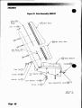
Crank and Bottom Bracket Assembly
Drive Chain
Fan
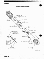
Fan Shaft Assembly
Freewheel
Handlebar/Console Mounting Tube
Intermediate Shaft Assembly
Pedals
45
46
45
53
49
50
51
50
46
50
53
Peg. vi
•
CONTENTS
Poly-V Belt
Poly-V Pulley
Seat
Seat Location Post (3000 CE only)
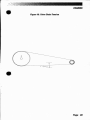
Seat Tray (3600 RC onlyl
50
50
47
4B
49
GROUNDING INSTRUCTIONS
NOTICE OF FCC COMPLIANCE
56
55
APPENDICES
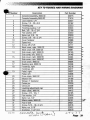
How to Order Parts
Figures 5 - 21
Wiring Diagrams 1 - 4
Key to Figures 5 - 21 and Wiring Diagrams 1- 4
57
58
75
79
LIST OF ILLUSTRATIONS
Figure 1. Spinnaker™ Systems Console, BASIC EXERCISE Program
Spinnaker Systems Console
Figure 2.
Spinnaker Systems Console, Power Test
Figure 3.
Spinnaker Systems Console, Group Race
Figure 4.
Leveling Adjustment Cap
Figure 5.
Power Supplies
!M
Figure 6.
Cover Fastener Location, 3000 CEn.t
Figure 7.
Figure 8. Cover Fastener Location, 3600 RC
Figure 9. Cover Fasteners
Figure 10. Right Side View. 3000 CE
-~ 11.
Left Side Vi ew, 3000 CE
re 12. Right Side View, 3600 RC
Figure 13. Left Side View. 3600 RC
Figure 14. Seat Adjustment Pin Assembly, 3000 CE
Figure 15. Seat Assembly, 3600 RC
Figure 16. Drive Chain Tension
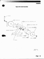
Figure 17. Fan Shaft Assembly
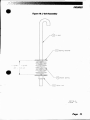
Figure 18. J-bolt Assembly
Figure 19. Intermediate Shaft Assembly
Figure 20. Crank Assembly
Figure 21. Fan Shaft Assembly Cross Section
Figure 22. Grounding System
11
11
18
18
58
59
60
61
62
63
64
65
66
67
68
69
70
71
72
73
74
55
LIST OF TABLES
Table 1.
Table 2.
Table 3.
Table 4.
Language Codes
Specifications
Fitness Rating Norms
Character Codes
7
8
16
23
Pllge vii
CONTENTS
Table 5.
Table 6.
Console Codes
Preventive Maintenance Schedule
e
28
LIST OF WIRING DIAGRAMS
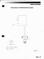
Wiring Diagram 1. Wall-Mounted Power Supply
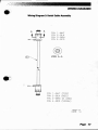
Wiring Diagram 2. Main Cable Assembly
Wiring Diagram 3. Serial Cable Assembly
Wiring. Diagram 4. 8' D.C. Power Cable Assembly
75
76
77
78
•
Peg. viii
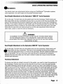
SAFETY GUiOEUNES
~/MPORTANT SAFETY INSTRUCTIONS I
ELECTRICAL GUIDEUNES FOR SAFELY OPERATING THE STAIRMASTER
SPINNAKER'" SYSTEMS CYCLE ERGOMETER
When using any electrical equipment, several basic precautionary guidelines should
always be strictly enforced. Among the safety precautions to which you should adhere
when operating the Spinna er systems cycle ergometer are the following:
1.
Read all instructions thoroughly before using the StairMaster Spinnaker systems
cycle ergometer.
IOANGERI
2.
To reduce the risk of electric shock:
• Always unplug the machine from the electrical outlet before cleaning,
performing maintenance, or making repairs.
IWARNINGI
•
3.
To reduce the risk of burns, fire, electric shock, or injury to individuals:
• Always unplug the power supply from the outlet before putting on or taking
off parts. Never attempt any adjustments or repairs while someone is
exercising on the machine.
• Closely supervise the Spinnaker systems cycle ergometer whenever it is used
by, or near children, invalids, or disabled persons. Keep children away from
the pedal crank assembly (or other similar moving parts). A serious injury
could result from an infant's or a small child's fascination with the moving
components of the exercise machine.
• Keep your hands away from all moving parts and keep your feet firmly planted
on the pedals while exercising. Do not operate with the side panels removed.
• Use the Spinnaker systems cycle ergometer only for its intended use as
described in this Manual. Do not use attachments or accessories that are not
genuine products provided by StairMaster Sports/Medical Products, Inc.
• Never operate the Spinnaker systems cycle ergometer if it has a damaged
cord or plug, if the power is not applied, if the console or machine does not
appear to be operating properly, if it has been dropped or damaged, or if the
power supply has been dropped into water. Call the Customer Service
Department of StairMaster Sports/Medical Products, Inc. at (800) 331-3578 to
arrange for damaged parts to be returned to our manufacturing facility for
Page
1
SAFETY GUIDEUNES
•
•
•
•
•
•
examination and repair. International customers may contact their local
distributor. Do not attempt to use the equipment until all problems have been
corrected.
Connect the power supply to a properly grounded outlet only (refer to the
grounding instructions section in this Manuan.
Keep the power supply cord and the DC cable away from heated surfaces.
Never drop or insert any object into any opening on the machine (except when
lubricating the chain).
Do not use the machine outdoors.
Do not operate where aerosol (spray) products are being used or where
oxygen is being administered.
To disconnect the machine, remove the wall-mounted power supply-{)r the
AC power cord plug, if applicable-from the AC wall outlet.
Failure to follow all guidelines may compromise the effectiveness of the exercise
experience, expose yourself (and possibly others) to injury, and reduce the
longevity of the machine.
I SAVE THESE INSTRUCTIONS I
Page 2
INSTALLATION INSTRUCTIONS
.ore leaving the StairMaster manufacturing facility in Tulsa. Oklahoma. your
~irMaste~
Spinnaker" systems cycle ergometer was thoroughly inspected and tested
to ensure that it operates properly. To minimize damage while in transit. your machine
was carefully prepared for shipment.
To transport your Spinnaker systems cycle ergometer into a building, a doorway
width of at least 22 inches (56 cm) is required. Once inside. the machine should be placed
on a solid, level surface near an AC wall outlet (120 volts are required for Spinnaker
systems cycle ergometers in the United States, Canada and Japan).
Before your Spinnaker systems cycle ergometer is ready to use, it will require
minor assembly.
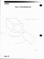
1.
The Spinnaker systems cycle ergometer has four leveling adjustment caps to
compensate for uneven floors. Each face of the square cap is a different thickness
(refer to Figure 5). If you need to level the bike, turn the appropriate adjusting
cap(s). Then, check the stability of the bike and readjust the leveling caps if
necessary.
2.
The Spinnaker cycle ergometers which are intended for single-bike operation in
the United States, Canada and Japan use a wall-mounted power supply that
plugs direc Iy into a 120-volt. three-prong AC wall outlet (refer to Figure 6). This
power supply has a permanently attached DC power cord that connects to a
single Spinnaker systems cycle ergometer.
.&
WARNING
TO REDUCE RISK OF ELECTRICAL SHOCK AND FIRE. DO NOT CONNECT MORE THAN
ONE SPI NAKER SYSTEMS CYCLE ERGOMETER TO THE WP-l MODEL POWER SUPPLY.
DO OT AITEMPT TO USE A STAIRMASTER PS-5 POWER SUPPLY.
Spinnaker systems cycle ergometers that are serially linked for the group
racing and team race option as well as Spinnaker systems cycle ergometers that
are sold for use outside of the United States, Canada or Japan (both single-use
and serially-linked) use different power supplies (refer to Figure 6). These power
supplies are small floor models with cables that must be connected to the power
supply unit.
.&
WARNING
TO ELIMINATE A POSSIBLE FIRE OR SHOCK HAZARD AND TO PREVENT SEVERE
DAMAGE TO THE MACHINE, USE ONLY THE POWER SUPPLY APPROVED FOR USE WITH
THIS EQUIPMENT. IN ADDITION, YOUR MACHINE MUST BE PROPERLY GROUNDED.
Page
3
INSTALLATION INSTRUCTIONS
Refer to the ".Grounding Instructions" section of this Manual if the wall •
outlet does not accept a three-prong plug. If you do not have the correct power
supply. contact the Customer Service Department of StairMaster Sports/Medical
Products. Inc. at (800) 331-3578 to order the correct power supply before
proceeding. International customers may contact their local distributor.
3.
Single-use power supply configuration (United States. Canada. and Japan):
If you have a single Spinnaker systems cycle ergometer or if you have more than
one Spinnaker systems cycle ergometer but do not want to connect your machines
together for group racing. perform the following instructions to connect power to
each Spinnaker systems cycle ergometer. If you have more than one Spinnaker
systems cycle ergometer and want to use the group race and team race features.
go to step 4. If you have a single Spinnaker systems cycle ergometer that will be
operated outside the United States. Canada or Japan. go to step 5.
• Plug the power supply into the AC wall outlet.
• Connect the DC power cable from the power supply to the power
connector located just inside the right or left side cover of your
machine (refer to Figure 7 or 8). Ensure the power connector cap is
installed on the power connector that is not in use.
• Observe the console. It should emit a tone. scroll a software revision
level message across the text bar and display the ATIRACT mode on the
console screen. If it does not do this. unplug the power supply and plug
it back in. If the sound and/or the displays are still not present. call the
Customer Service Department of StairMaster Sports/Medical
Products. Inc. at (800)331-3578. International customers may contact
their local distributor.
•
• Go to step 6.
4.
Group race power supply configuration
To connect multiple Spinnaker systems cycle ergometers (up to a maximum of
five) to take advantage of the group race features. perform the following steps:
• Ensure that the input AC power rating marked on the power supply
matches the available power and that you are not using the wallmounted power supply. If you do not have the correct power supply.
contact the Customer Service Department of StairMaster Sports/
Medical Products. Inc. at (800) 331-3578 to order the correct power
supply before proceeding. International customers may contact their
local distributor.
"eg.
4
INSTALl.AnON INSTRUCnONS
&
WARNING
TO REDUCE RISK OF ELECTRICAL SHOCK AND FIRE. DO NOT CONNECT MORE THAN
FIVE (5) SPINNAKER SYSTEMS CYCLE ERGOMETERS TO THE PS-6 MODEL POWER SUPPLY.
USE ONLY THE POWER SUPPLY APPROVED FOR USE WITH THIS EQUIPMENT.
IN ADDITION. YOUR MACHINE MUST BE PROPERLY GROUNDED.
•
• Line up the Spinnake( systems cycle ergometers in a row. Although
other configurations may be used. for the sake of clarity. the following
instructions will address a single row.
• Connect the DC power cable to either the machine on the far left- or
the far right-hand end of the row. Use the connector located just inside
the right side cover (if you are connecting the far right bike) or the left
side cover (if you are connecting the far left bike). Connect the other
end of the DC cable to the power supply.
• Place the PS-6 model power supply on the floor near the AC wall
outlet closest to this bike.
• Plug the AC power cord into the AC wall outlet.
• Connect the other end of the AC power cord to the PS-6 model power
supply.
• Switch on the power supply and observe the console. It should emit a
tone, scroll a software revision level message across the text bar and
display the ATIRACT mode on the console screen. If it does not, switch
off the power supply and then turn it back on. If the sound and/or the
displays are still not present. call the Customer Service Department at
StairMaster Sports/Medical Products, Inc.
• If the console is working properly, turn off the power supply and
connect one end of the serial cable to the free power connector on this
bike. Connect the other end of the serial cable to the power connector
on the next bike in line. Continue linking the remaining bikes with
serial cables.
• Turn on the power supply. If any console fails to power up, call the
Customer Service Department at StairMaster Sports/Medical
Products, Inc.
• Finally. set the console address numbers so that race information can
be sent to all of the bikes during the group race. These address
numbers range from #1 to #5. Each bike must have a unique number
within this range. During the group race, the bike with the address #1
will be displayed in the top lane; the bike with the address #2 will be
displayed in the next lane down and so on, with the #5 bike in the
bottom lane. Press [up ARROW]. (1). 17], [4]. [6]. [ENTER) on the first bike's
console. The console will prompt you to enter the bike number. Press
[1), [ENTER). Go to the next Spinnaker systems cycle ergometer in line.
Press [up ARROW]. [1]. 17], [4]. [6]. [ENTER] on this console. Press [2].
Peg. 5
INSTALLAnON INSTRUcnONS
[ENTER). for this bike. Set up the remaining bikes until all bikes have.
unique address from #1 to #5.
• Go to step 6.
5.
The International power supply configuration (International 220-240 VACl
To connect power to a single Spinnaker" systems cycle ergometer in countries
other than the United States. Canada, or Japan. perform the following steps:
• Ensure thatthe input AC power rating marked on the power supply
matches the available power. If you do not have the correct power
supply, contact the local StairMaste'" Sports/Medical Products, Inc.
distributor to order the correct power supply before proceeding.
~WARNING
TO REDUCE RISK OF ELECTRICAL SHOCK AND FIRE. DO NOT CONNECT MORE
THAN FIVE (5) SPINNAKER SYSTEMS CYCLE ERGOMETERS TO THE IPS-3 MODEL POWER
SUPPlY. USE ONLY THE POWER SUPPlY APPROVED FOR USE WITH THIS EQUIPMENT.
IN ADDITION. YOUR MACHINE MUST BE PROPERLY GROUNDED.
• Connect the DC power cable to the connector located just inside the
right or left side cover of the Spinnaker systems cycle ergometer (refer
to Figure 7 or 8). Ensure the power connector cap is installed on the
power connector not in use. Connect the other end of the DC cable to
the power supply.
• Place the IPS-3 model power supply on the floor near the AC outlet •
closest to the bike.
• Plug the AC power cord into the AC wall outlet.
• Connect the other end of the AC power cord to the IPS-3 model power
supply.
• Switch on the power supply and observe the console. It should emit a
tone. scroll a software revision level message across the text bar and
display the ATIRACT mode on the console screen. If the console does
not do this, switch off the power supply and then turn it back on. If the
sound and/or the displays are still not present, call the local
StairMaster Sports!Medical Products. Inc. distributor.
6.
The console is set at the manufacturing facility to English language prompts and
English units. While the console is in the AnRACT mode, you can set the console
for foreign language prompts or metric units. To change the language of the
prompts, press [up ARROW]. [7). [4). (2). [4]. [ENTER]. Press the code number
corresponding to the desired language according to Table 1 and then [ENTER]. If the
software version does not have the desired language, contact the Customer
Service Department at StairMaster Sports/Medical Products. Inc. to obtain the
Page 6
INSTALlATION INSTRUCnONS
•
correct software version.
To change the console to metric units, press [up ARROW], [9], [7], [6). [0],
[ENTER). Press [1], [ENTER] when prompted. To change the console to back to English
units, press [up ARROW], [9). (7). [6], [0], [E TER). Press [0], [ENTER) when prompted.
Table 1. Language Codes
Language
EnQlish
French
German
Italian
Soanish
Swedish
12.
Code Number
Version NA" Version "8" Version Ne-
0
1
0
2
1
2
0
1
2
Your Stair as er Spinnaker systems cycle ergometer is now ready for use.
PHYSICAL DIMENSIONS AND ELECTRICAL SPECIACATIONS OF THE
STAIRMASTER SPINNAKER~ SYSTEMS CYCLE ERGOMETER
The dimensions and electrical specifications of the StairMaster Spinnaker systems cycle
ergometer are listed in Table 2. To reduce the hazard of electrical shock. place the power
supply in a location away from the machine and away from exposure to perspiration. Do
no place the power supply on a carpe because the power supply may overheat.
.,mount power supplies should be plugged directly into the AC wall outlet. Customlength DC cables, bracke s for multiple power supplies, and other accessories are
available from StairMaster Sports/Medical Products, Inc. Refer to the Appendix "How to
Order Parts" for the phone number of the office nearest you.
Page
7
INSTALlATION INSTRUCTIONS
T.ble 2. Specific.tions of the Spinn.ke'· Syste_ Cycle Ergometer
Dimensions
3000 CE"I
3600 RCTII
length
Width at the:
base
handlebars
Height at the handlebars
Weight
46 inches (117 cm)
62 inches (157 cm)
19 inches (48 cm)
22 inches (56 cm)
57 inches (145 cm)
125 pounds (57 kg)
19 inches (48 cm)
22 inches (56 cm)
42 inches (107 cm)
150 pounds (68 kg)
110-120 VAC, 50/60 Hz
9-15 VDC
.085 Amp
15 Watts
110·120 VAC, 50/60 Hz
9-15 VDC
.085 Amp
15 Watts
110-120 VAC, 50/60 Hz
10-16 vdc
2.5 Amps
60 Watts
110-120 VAC, 50/60 Hz
10-16 vdc
2.5 Amps
60 Watts
Power Supply Ch.,.cteristics
Wall-mount unit, WP-l
input voltage
output voltage
maximum output current
input power consumption
Optional power supply, PS-6
input voltage*
output voltage
maximum output current
input power consumption
* Optional power supplies intended for use outside the United States, Canada and Japan
are available for 220-240 VAC, 50/60 Hz. power requirements. These power supplies
have not been evaluated by Underwriters laboratories. Inc.
•
...
".
BASIC OPERATING INSTRUCnONS
eUSTMENTS
You should check two adjustments before using your StairMaster- Spinnaker systems
cycle ergometer: the seat height and the pedal footstrap length.
Seat Height Adjustment on the Spinnaker'" 3000 CE- Cycle Ergometer
Sit on the seat. Put both feet onto the pedals and into the footstraps. Pedal slowly and
then stop when one leg is extended and your foot is as close to the floor as possible. The
knee of the extended leg should be slightly bent when the sole of your foot is parallel to
the floor. If you need to adjust the seat height. get off the bike and stand to one side. The
seat adjustment knob is located on the frame tube just below the front part of the seat.
Hold onto the seat with one hand and pull out on the seat adjustment knob with your
other hand. Lower or raise the seat as necessary.
&.
WARNING
TO ELIMINATE THE RISK OF INJURY. DO NOT ADJUST THE SEAT HEIGHT WHILE
ON THE SPINNAKER 3000 CE CYCLE ERGOMETER. MAKE SURE THAT THE SEAT
ADJUSTMENT PIN CO PLETELY ENGAGES THE HOLE IN THE SEAT POST BEFORE
REMOUNTING THE BIKE.
Seat Height Adjustment on the Spinnaker 3600 RC- Cycle Ergometer
Sit on the seat. Put both feet onto the pedals and into the footstraps. Pedal slowly and
stop when one leg is extended. The knee of the extended leg should be slightly
. The seat adjustment lever is in front of the seat base. Remain seated and keep your
feet on the pedals. Pull up on the lever and slide forward or backward as necessary.
Release the lever and make sure the seat is locked in place by trying to move the seat
forward and backward.
Footstrap Adjustment
To ensure your feet are properly secured to the pedals. you need to check the position of
the footstraps. Position your foot so that the ball of your foot is over the pedal spindle.
The pedal footstraps should be tight enough to secure your feet to the pedals but not so
tight so as to cut off the circulation. If you need to adjust the footstrap length. get off the
bike and stand to one side. There are two adjusting holes on the inside footstrap mount
and four holes on the outside footstrap mount. Most shoes can be accommodated by
adjusting the outside mounting holes. To make the necessary adjustments. grasp the
pedal with one hand and the outside end of the footstrap with your other hand. Carefully
pull the outside end of the footstrap off the tab on the pedal. Insert the proper hole of the
footstrap onto the pedal tab. If you need to make additional adjustments. repeat the
process with the inside mounting holes of the footstrap.
BASIC OPERATING INSTRUCTIONS
THE ATTRACT MODE
The console is in the ATIRACT mode when the Spinnaker systems cycle ergometer is idle
and ready for use. A graphic of a bicycle and a sailboat with a spinnaker scrolls across
the display while the Spinnaker systems cycle ergometer is in the ATTRACT mode. You can
program your own message to scroll across the text bar. Refer to the "Customizing the
Text Bar Scrolling Message" section of this Manualfor further instructions on programming your own messages for the ATIRACT mode.
THE BASIC EXERCISE PROGRAM
Once you have properly adjusted the seat and the footstraps, you are ready to use your
Spinnaker systems cycle ergometer. To start the BASIC EXERCISE program, simply begin
pedaling. The ATIRACT mode ends after you pedal 40 revolutions per minute for at least
five seconds. Press [ENTER) when prompted. The BASIC EXERCISE program is a self-paced
workout that calculates all metabolic feedback except MET Level. Two dots will light up
at the bottom of the display (refer to Figure 1). As you pedal. the dots will advance
around the perimeter of the display in a clockwise direction. Each lap around the display
is equivalent 01/4 of a mile. The faster you pedal, the faster the dots move. The elapsed
time of your workout, in minutes:seconds. is shown in the middle of the display.
The left side of the text bar displays your current pedal rate in revolutions per
minute. Press [2ICYCU GSPEED) to change the ext bar feedback from pedal rate to cycling
speed in miles per hour (or in kilometers per hour. if your console is set up for metric
units). Press [WORKOUT STATS) and all of the performance feedback will continuously scroll
across the text bar-with the exception of MET Level.
Press [CLEAR) to end the BASIC EXERCISE program. Your summary workout sta
will scroll across the text bar. You can press any function keypad button during he
scrolling summary and stop a ha statis ic. You have 10 seconds 0 press another
function eypad button before the console goes in 0 he ATIRACT mode. Your workout
stats are stored in he console memory until the next exercise program is started. Press
[WOR OUT STATS) to scroll the summary information across the text bar.
In addition to the BASIC EXERCISE program, there are nine other exercise
programs on the Spinnaker systems cycle ergometer. Detailed descriptions of each of
these programs are presented in the next section of this Manual.
Page 10
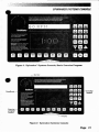
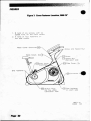
SPINNAKER SYSTEMS CONSOLE
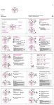
Figure 1: Spinnaker Systems Console. Basic Exercise Program
Function
Deodfronts
keypad
Exercise
~~m
Figure 2: Spinnaker Systems Console
Page 11
SPINNAKER SYSTEMS CONSOLE
StairMaster~
The
Spinnaker"' systems console is divided into four sections: the text
the display, the function keypad and the exercise program keypad (refer to Figure 2).
b.
TEXT BAR
Information regarding workout statistics and data entry is displayed or scrolled across the
text bar. There are five words under the text bar that are only visible when lit from
behind-an arrangement which is called a deadfront. The deadfronts are used in
conj",nction with the text displayed in the text bar. Reading from left to right, the
deadfronts are: ACTUAL, BEHIND, AHEAD, TARGET, and TIME.
The ACTUAL, TARGET, and TIME deadfronts are lit at certain times during the
course of most exercise programs. The feedback in the text bar is lined up above the
deadfronts. The ACTUAL and TARGET deadfronts are used to compare your pedal rate
(ACTUAL) to the pedal rate you need to maintain to keep pace with the program
(TARGET). For example, the default display for the INTERVAL ONE program is pedal rate.
Reading from left to right, the text bar would show the pedal rate of the user at that
particular instant (ACTUAL); the units-in this case, RPM; the pedal rate you need to
maintain to keep pace with the program (TARGET); and the time, in seconds, remaining in
the current interval (TIME).
DISPLAY
The display provides a graphical depiction of your actual pedal rate compared to the
target pedaling rate set by the pacer. The display graphics are slightly different for each
program; refer to the program descriptions in the "Exercise Program Keypad"section of
this Manualfor more details.
RJNCTlON KEYPAD
•
The function keypad is located on the right side of the console. Ten of the keys on the
keypad have two pieces of information on them-a number and a workout statistic.
Before the exercise program begins, the numbers are used to enter data in response to
the console prompts. During or immediately after the exercise program, the function
keypad keys are used to recall workout statistics which are then displayed on the text
bar.
1.
PEDAL RATE is the number of pedal revolutions per minute, also referred to as
cycling cadence. During an exercise program, this button displays the cycling
cadence at that particular moment in time. After you have completed your
exercise program, the average cadence for the duration of the exercise bout is
displayed.
2.
CYCLING SPEED is the equivalent speed, in miles per hour (or kilometers per hour
if your console is set to metric units), you would be traveling on a bicycle outdoors
while riding at the same relative intensity. During an exercise program, this
P.ge 12
SPINNAKER SYSTEMS CONSOLE
button displays the current speed. After you have completed your exercise
program, the average speed for the duration of the exercise bout is displayed.
3.
DISTANCE CYCLED provides a cumulative total of the equivalent distance, in
miles (or kilometers if your console is set to metric units), you would have traveled
while riding a bicycle outdoors at the same relative intensity.
4.
TOTAL CALORIES provides a cumulative total of the Calories expended during a
particular workout. Calories expended is probably the most common way to
measure the energy cost of exercise. Since the energy content of food is expressed in Calories, a convenient way exists to control or manage your body
weight. When your total energy intake is less than your total energy output, you
lose weight and vice versa. Technically, a Calorie is a measure of heat. One
Calorie is the amount of heat needed to raise the temperature of one liter (or one
kilogram) of water one degree Celsius.
5.
EXERCISE LEVEL provides different information depending on the exercise
program you select:
•
INTERVAL programs - the intensity level during the workout; the recommended training level during the workout summary.
• GROUP RACE - your placing during the race; your placing and elapsed time
during the workout summary.
• ROAD RACE - the pacer speed during the race; the average pacer speed
during the workout summary.
•
7.
WORKOUT TIME displays the total time, in minutes and seconds, that you have
been exercising.
POWER OUTPUT provides a measure of how hard you are exercising. In order to
better understand this measure, it is important to appreciate the differences
between work, power, and energy. Work is the product of an applied force
multiplied by the distance over which the force is applied. Power is the rate of
doing work, or work divided by time. Energy, on the other hand, is the capacity to
do work. Power output is measured in units known as watts (746 watts = 1
horsepower). Since power is a rate, power output does not accumulate over time
and will not change during your workout unless you change your pedal rate.
During your exercise program, this button displays your current power
output. After you have completed your exercise program, the average power
output during your workout is displayed.
8.
MET LEVEL is the relative energy cost of exercise. One MET is equivalent to the
resting oxygen consumption of about 3.5 milliliters of oxygen per kilogram of body
mass per minute Iml Oz·kg-1.min- 1). For example, exercising at 10 METs requires
ten times the resting metabolic rate or about 35 ml 0z·kg-1.min- 1 .
Paga 13
SPINNAKER SYSTEMS CONSOLE
During the exercise program, this button displays the MET level at which YOu.
currently exercising. After you have completed your exercise program, the average
MET level during your workout is displayed.
9.
TOTAL WORK provides a cumulative total of the amount of work performed during
a workout. Work is expressed in kilogram-meters. A kilogram-meter (kgm) is the
amount of force necessary to move a one kilogram mass (2.2 pounds) one vertical
meter (3.3 feetl. Since work is a quantity, the total amount of work increases with
time.
10.
The DISPLAY button allows you to return the text bar graphics to the default
display for that program. On most exercise programs, the default display is PEDAL
RATE.
11.
The WORKOUT STATS button continuously scrolls the information on all nine
performance feedback buttons across the text bar. This information can be
displayed at any time during a workout. It is also stored in the console memory
until the next exercise program is started. You can press any function keypad
button during the scrolling summary and stop at that statistic. You have 10
seconds to press another function keypad button before the summary ends.
12.
The UP and DOWN ARROWS increase or decrease, respectively. the exercise
intensity level of the I TERVAL programs. The exercise intensity level ranges from
#1 (the easiest) to #20 (the most difficult). The UP and DOWN ARROWS also
change the computer pacer speed during the ROAD RACE.
13.
The ENTER button confirms selections and stores the information used to
calculate the performance feedback into the console memory.
•
14.
The CLEAR button erases data from the console before IE TER] is pressed.
Pressing the CLEAR bu ton once during a workout ends the exercise program and
begins the workout summary. Press the CLEAR button twice to return to the
ATTRACT mode.
15.
The YES and 0 buttons are used to respond to data entry prompts.
16.
The RESET button always returns the console to the ATTRACT mode.
EXERCISE PROGRAM KEYPAD
The exercise program keypad is located below the display and to the left of the function
keypad. While the console is in the ATTRACT mode. press one of the exercise program keys
to select the desired workout.
1.
SELF PACE is similar to the BASIC EXERCISE program described earlier. with the
that your MET level can be calculated during the SELF PACE program.
ex~eption
Page 14
•
2.
SPINNAKER SYSTEMS CONSOLE
You need to enter your body weight and the program duration (from 5-45 minutes)
before starting the program. Once you have entered the required information, two
dots will light up at the bottom of the display. As you pedal, the dots will move
around the display in a clockwise direction. Each lap around the display is
equivalent to 1/4 of a mile. The faster you pedal, the faster the dots move. The
elapsed time of your workout, in minutes:seconds, is shown in the middle of the
display.
The FIT TEST is a program that estimates your maximal aerobic capacity based on
your heart rate response to submaximal exercise. You will be prompted to enter
your body weight, your age and your gender.
Once you have entered the required information, two dots will light up at
the bottom of the display. As you pedal, the dots will move around the display in a
clockwise direction. The target pedaling rate is shown in the middle of the
display. Your actual pedaling rate, as well as the target pedaling rate, is shown in
the text bar. The goal is to match your pedaling rate to the target pedaling rate.
The timer will count down in seconds.
•
3.
The FIT TEST is a modified YMCA protocol. You will warm-up for three
minutes (180 seconds) at a steady pace and then be prompted to enter your heart
rate You have five seconds to find your pulse and 10 seconds to count your pulse.
Enter the lO-second count when you are prompted. If you are using a heart- or
pulse-rate monitor, enter your heart rate at the end of the ten-second period. You
will then continue to exercise for three-minute bouts of increasing intensity until
you reach a point where you have entered two heart rate responses between 19
and 25 counts (115-150 beats per minute). This test typically lasts from 9 to 15
minutes.
At the end of the FIT TEST. your results will be scrolled across the text bar.
Your estimated maximal aerobic capacity, expressed in METs, will be the first
statistic shown. Next, your test results will be compared to normative values for
others of your age and gender. These normative values are based on values
developed by the world renowned exercise physiologist. Dr. Per Olaf Astrand, and
are shown in Table 3. Your results are stored in the console until the next exercise
program is started. To review your test results, press [WORKOUT STATS].
The POWER TEST is a modified Wingate anaerobic power test. This test requires
you to enter your body weight, age, and gender. You start the test with a threeminute warm-up and then are required to perform an all-out sprint for 30 seconds.
The graphic display and text bar feedback for the warm-up is the same as
described in the FIT TEST above. Messages describing the test scroll across the
text bar during the warm-up. With 5 seconds left in the warm-up, the console will
count down to the start of the test.
Page 15
SPINNAKER SYSTEMS CONSOLE
Rtn. . Reting Norms for Spinnikerllll Systems Cycle ErgOm. . . .
Aerobic Rtn. . Tlst (METs)
Tlble 3.
Gender/Aae
Men
20-29
30-39
40-49
50-59
60-69
Women
20-29
30-39
40-49
50-59
60-69
Low
Fair
Averaal
Abovi Averue
SUDerior
<10.8
<9.7
<8.6
<7.1
<6.0
11.1-12.3
10.0-11.1
8.8-10.0
7.4-B.8
6.3-7.4
12.6-16.0
11.4-14.6
10.3-13.4
9.1-12.3
7.7-11.1
16.3-19.7
14.8-18.3
13.7-17.1
12.6-15.7
11.4-14.0
20.0+
18.6+
17.4+
16.0+
14.3+
<8.0
<7.7
<7.1
<6.0
<4.8
8.3-9.7
8.0-9.4
7.4-8.8
6.3-7.7
5.1-6.3
10.0-13.7
9.7-13.4
9.1-12.8
8.0-11.7
6.6-10.3
14.0-16.8
13.7-16.6
13.1-16.0
12.0-14.0
10.6-12.6
17.1+
16.8+
16.3+
14.3+
12.8+
&
WARNING
THIS TEST IS VERY STRENUOUS AND REQUIRES A GREAT DEAL OF EFFORT. TO AVOID
BODILY INJURY, CONSULT A PHYSICIAN BEFORE TAKING THIS TEST IF YOU ARE
CONCERNED ABOUT YOUR ABILITY TO PERFORM THIS TEST.
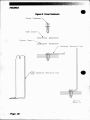
The message "GO" will appear in the text bar to prompt you to begin the test. •
sighting the prompt, pedal as fast as you can for the entire 30-second period.
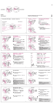
During the test, your power output will be shown in two ways on the display
screen-numerically in watts and graphically as a power curve (refer to Figure 3).
The dots under the power curve light up as you pedal faster. During the test, the
objective is to pedal as fast as you can for as long as you canJ@ text bar shows
the time left in the teit~
- -___
_ _ _ '"
~==:::::::::==:::::::::;::
iF
Your test results are displayed during the 90-second cool-down phase.
Your power output over the 30-second test period are shown in the display as a
graph and in the text bar in three ways: peak power, peak power per kilogram of
body mass, and average power. Your average power per kilogram of body mass is
compared to normative values for others of your age and gender. Your results are
then stored in the console until the next exercise program is started. To review
the results of your test, press [WORKOUT STATS).
4.
The INTERVAL programs vary the ratio of easy pedaling and fast pedaling based
on a 15-second interval continuously throughout the duration of the program.
INTERVAL ONE uses three periods of easy pedaling and one period of fast
P.,. 16
SPINNAKER SYSTEMS CONSOLE
•
pedaling. In this program, you are required to pedal slowly for 45 seconds and
then pedal fast for 15 seconds before the cycle is repeated. INTERVAL TWO
alternates two slow interval periods (a total of 30 seconds) with two fast interval
periods (a total of 30 seconds). INTERVAL THREE alternates 15 seconds of slow
pedaling with 45 seconds of fast pedaling.
Press the desired INTERVAL program button. You are also required to enter
your body weight, the intensity level from #1 (the easiest) to #20 (the most
difficult), and the duration from 5to 45 minutes.
The display is equivalent to a 1/10-mile race track. Your bike is represented as two dots in the outer lane. The computer pacer is the single dot in the
inner lane. The computer pacer will advance in a clockwise direction around the
perimeter of the display as soon as the program starts. Your objective is to pedal
to keep up with the pacer. The faster you pedal, the faster your dots move and
vice versa. The target pedaling rate is shown in the middle of the display.
As a default, the text bar displays pedal rate. Your pedal rate is shown
above the ACTUAL deadfront. The units are displayed to the right of the
numbers-in this case, the feedback units are pedal revolutions per minute
(RPM). The computer pacer pedal rate is shown above the TARGET deadfront. The
number of intervals left in the program are shown above the TIME deadfront. You
can change the text bar feedback by pressing the appropriate function keypad
button during the workout.
•
As your dots travel around the display perimeter, the finish line for that
interval will light up with one lap to go. The finish line may be anywhere around
the perimeter but when it shows up, it always signifies that there is one lap to go.
The goal is to tie or beat the pacer to the finish line. The AHEAD deadfront will
briefly flash if you beat or tie the pacer to the finish line. The BEHIND deadfront
will flash if the pacer beat you to the finish line.
You should cool down at the slow pedaling rate for one minute at the end
of the exercise program. The pacer dot will disappear, signifying the cool-down
period. Your workout stats are scrolled across the text bar after the cool-down
period. A recommended intensity level for your next workout, based on the
number of times you at least tied the pacer to the finish line, will also be shown
in the text bar. Your results are stored in the console until the next exercise
program is started. To review the results of your performance, you can press
[WORKOUT STATS).
Peg. 11
SPINNAKER SYSTEMS CONSOLE
Figure 3: Spinlaker"'Systems Console, Power Test
Figure 4: Spinnaker Systems Console, Group Race
Page 18
SPINNAKER SYSTEMS CONSOLE
The TEAM RACE ( IME TRIAL) is a four-bike race with two bikes per team. During
the race, teammates can draft each other. While drafting, the lead bike must
overcome a certain amount of wind resistance and the trailing bike has an
advantage while riding in the lead bike's slipstream. The trailing bike must stay
within two dots of the lead bike to remain in the draft. If the teammates work
together, dividing the drafting time, they will be able to attain a higher average
speed than if one bike is left behind.
The four people in the race press [TEAM RACE) to start the race. The first
person to press [TEAM RACE] will set up the race. Say, for example, the riders on
bikes 1and 3 are on one team and the riders on bikes 2 and 4 are on the
other team. The person in charge of the race set up will press (1), (3). [ENTEA). (2).
[4), [E TEA] when prompted to enter the teams. Bikes 1and 3 are on the first
team. Bikes #2 and #4 are on the second team. Refer to the "Group Race Power
Supply Configuration" section of the Installation Instructions in this Manualfor
additional information about setting the bike numbers.
Select the race distance by pressing a number key and then [E TEA). A fivemile race requires all participants to complete five one-mile laps. After the race is
set up, the person in charge must press [E TEA). All bike's text bars will then show
a five-second countdown to the start of the race.
•
The display for the TEA RACE is a series of five two-lap lanes, very
similar to the GROUP RACE display (refer to Figure 4), with he middle lane empty.
Each lane is separated by a row of lighted dots. The two ends of your bike's lane
are enclosed by two lit dots. The two bikes on team 1 are shown in the top two
lanes. The two bikes on team 2 are in the bottom two lanes. Using the example
race set up in the preceding paragraph, bike #1 is in the top lane; bike #3 is in the
next lane down; the middle lane is empty; bike 2 is in the fourth lane; and bike
#4 is in the bottom lane. The enclosure dots at the right end of your lane will
disappear once the race starts. A single enclosure dot remains lit at the left end
to indicate your lane.
On the first lap of the race, your bike is shown as a Single dot traveling
from left-to-right across the display. When your bike gets to the far right side of
the display, he dot will drop down a row and move bac toward the s arting line
from right-to-Ieft. One dot is added to your bike at the start of each lap. For
example, your bike is shown as one dot on the first lap and as five dots on the
fifth and final lap. Remember, you have to complete one lap as a 5-dot bike before
a 5-mile race is over.
The default statistic in the text bar is your pedal rate expressed in RPMs.
The number of laps remaining are counted down at the right side of the text bar.
The performance feedback can be changed from the default pedal rate by
pressing the desired button on the function keypad. The number of the bi e on
your team that is drafting is shown in parentheses between the performance
feedback and the lap counter.
Page 19
SPINNAKER SYSTEMS CONSOLE
tea.
Your team's elapsed time for the race is the finishing time of your
second place rider. In other words, your team is only as fast as the slowest rider.
Your team's standing in the race and your elapsed time are shown in the text bar
after you have completed the race. You also have access to all other workout
stats except MET level. The race results are stored in the console until the next
exercise program is started. You can press [WORKOUT STATS] to review the results
of your performance.
6.
The ROAD RACE is a race agains acomputer opponent. You will be prompted to
enter your body weight and the desired pace 0 the race. You have the choice
between a variable pace or a steady pace race. If you choose the variable pace,
the race is subdivided into three basic sections. The computer starts with a short
warm-up; the middle section is a slowly changing series of fast and slow
intervals; and the end of the race finishes with a fast sprint. If you selected the
steady pace race. the pace does not change over the course of the race. The
average speed of either race mode is still controlled by the pace you select.
Finally, you a e required to enter the distance of the race. Once you enter the
distance, your five-second countdown to the start will appear in the text bar.
The display is equivalent to 1/4 mile race track. You are represented as
two dots in the outer lane. The computer pacer is the single dot in the inner lane.
The computer pacer advances in a clockwise direction around the perimeter of the
display as soon as the program starts. In this race, you are required to pedal to
keep up with the pacer. The faster you pedal. the faster your dots move and vice
versa. The total number of laps is counted down to one in the middle of the
display.
As your dots travel around the display perimeter, a finish line arrow.
Iigh up with one lap to go. The goal is to tie or beat the pacer to the finish lin . t
you picked the variable pace race, start sprinting on the last lap! The AHEAD
deadfront will briefly flash if you beat or tied the pacer to the line. The BEHIND
deadfront will flash if the pacer beat you to the line.
After the race is completed. the program lets you cool down for oneminute. The pacer dot disappears to signify the start of the cool-down period.
Your workout stats are scrolled across the text bar after he cool-down period.
Your results are stored in the console until the next exercise program is started.
You can press [WORKOUT STATS] to review your results.
7.
The GROUP RACE is a race involving from two to five bikes. To start the GROUP
RACE, every participant needs to press [GROUP RACE]. The first person to press
[GROUP RACE] is required to respond to the race setup prompts. The participants can
choose to race with or without the drafting function activated. The person in
charge of the race setup must press [YES] to activate the draft mode or [NO] to
deactivate the draft mode. When the drafting mode is on, the leading bike must
overcome a certain amount of wind resistance. while the bikes following the lead
P.ge 20
•
SPINNAKER SYSTEMS CONSOLE
bike have the advantage of riding in the lead bike's slipstream. The trailing bikes
must stay within two dots of the bike ahead of them to stay in the draft. The
drafting mode is much like handicapping the s rongest rider while introducing
realistic bicycle racing s rategy. When the drafting mode is on, sometimes it is
the smartest, ra her than the strongest, rider who wins the race. When the
drafting mode is off, all participants are on an even, competitive footing.
Select the race distance by pressing a number key and then [E TER). A fivemile race requires all participants to complete five one-mile laps. After the race is
set up, the person in charge must press [E TER). All bike's text bars will then show
a five-second countdown to the start of the race.
The display for the GROUP RACE is a series of five two-lap lanes (refer to
Figure 4). Each lane is separated by a row of lighted dots. The two ends of your
bike's lane are enclosed by two lit dots. The enclosure dots at the right end of
your lane will disappear once the race starts. A single enclosure dot remains lit at
the left end to indicate your lane.
On the first lap of the race, your bike is shown as a single dot traveling
from left-to right across the display. When your bike gets to the far right side of
the display, the dot will drop down a row and move back toward the starting line
from right-to-Ieft. One dot is added to your bike at the start of each lap. For
example, your bi e is shown as one dot on the first lap and as five do s on the
fifth and final lap. Remember, you have to complete one lap as a five-dot bike
before a five-mile race is over.
•
The default s atistic in the text bar is your pedal rate expressed in RPMs.
The number of laps remaining are counted down at the right side of the text bar.
The performance feedback can be changed from the default pedal rate by
pressing the desired button on the function keypad. If the drafting mode is
activated, the number of the bike(s) drafting is shown in parentheses on the text
bar between the performance feedback and the lap counter.
The race does not end until the last bike finishes or quits the race.
Pressing [ClEAR) allows you to drop out of the race. Pressing [CLEAR) will also end
he race if only one other person remains in the race who has not finished.
Both your standing in the race and your total time are shown in the text
bar after you have completed the race. You also have access to all other workout
stats except MET Level. The race results are stored in the console until the next
exercise program is started. You can press [WORKOUT STATS) to review the results
of your performance.
Page 21
SPINNAKER SYSTEMS CONSOLE
CUSTOMIZING THE TEXT BAR SCROWNG MESSAGE
•
The message that scrolls across he text bar during the ATIRACT mode can be replaced
with a message of your choice. The console accepts messages up to 128 characters in
length. including spaces. To program your message:
1.
Encode your message using the character codes listed in Table 4.
2.
While the console is in he ATIRACT mode. press [up ARROW). (7). (6). (0). (7). [E TER].
3.
Enter the two-digit code for each letter of your message. The letter will appear in
the text bar as you press the second digit of each code. Do not press [E TERI
between the code numbers.
4.
For example. to program the message "EXERCISE IS FUN". press [UPARRowl. (7).
(6). [01. (7). [ENTERI. Then press [1). (5). (3). [41. [1). [51. [2]. [8]. [1). (3). (1). [9). [2). (9).
[11. (5). (1). [0). (1). (9). [2). (9). (1). [0]. (1). [6). [3). [1]. [2). [41. [ENTER]. At that point.
your message will begin scrolling. The console is again in the ATIRACT mode.
5.
If you make a mistake while entering the codes. press [CLEARI to erase the last
character entered.
EOmNG THE SCROWNG MESSAGE
1.
While the console is in the ATTRACT mode. press [up ARROW). (7). [61. [01. (7), [E TERI
to display the first character of the message onto the text bar.
2.
Press the [up ARRowl and [DOW ARROW] to scroll through he message charac.
by-character.
3.
Press [CLEARI to delete the last character displayed on the text bar. Press [E ER] 0
end the editing process.
4.
To edit multiple characters at one time. press [91. [9). [E TER] to erase all of the
characters to the right of the last character displayed on the text bar.
5.
To erase the entire message. press [UPARROW]. [11. [0). [5]. [E TERI while in the
ATTRACT mode.
6.
The edited message will scroll across the text bar. If you have erased the entire
message. the text bar area will be blank when you press [ENTER].
7.
Press the [UPARROW). (2). (1). [2]. (3). [E TEA] to display the default scrolling
message on the text bar.
Page 22
•
SPINNAKER SYSTEMS CONSOLE
Press [up AR ow]. [2]. [ ]. [2]. [1]. [E TE J to display your cus om scrolling message
on the text bar.
Table 4.
0
1
2
3
4
5
6
7
8
9
SPACE
A
B
C
0
E
F
G
H
I
•
J
K
L
Character Codes for the Scrolling Message
TrnrfP
00
01
02
03
04
05
06
07
08
09
10
11
12
13
14
15
16
a
P
Q
R
S
T
U
V
W
X
Y
Z
A
0
b
18
~
A
19
20
21
22
N
17
r r.nrlp
1rnrlp
M
N
A
Q
E
23
24
25
26
27
28
29
30
31
32
33
34
35
36
37
38
39
40
41
42
43
44
45
I
A
T
E
A
C
E
i
+
$
,
%
?
0
!
-
.)
(
/
46
47
48
49
50
51
52
53
54
55
56
57
58
59
60
61
62
63
64
65
66
67
68
Page 23
•
SPINNAKER SYSTEMS CONSOLE
CODES FOR THE SPINNAKER"" SYSTEMS CONSOLE
There are several console functions that can be accessed by entering a numerical code. A
list of the codes and the corresponding functions is presented in Table 5.
Table 5. Console Codes
Code
UP ARROW, 105,
ENTfR
UP ARROW, 107,
ENTER
0
1
2
3
4
UP ARROW,1746,
ENTER
UP ARROW,2121,
ENTER
UP ARROW,2123,
ENTER
UP ARROW,7424,
ENTER
UP ARROW, 7607,
ENTER
99. ENTER
UP ARROW, 7703,
ENTER
UP ARROW, 9760,
ENTER
0
1
Page 24
Function
Clears the custom programmed scrolling message
Activates the Diagnostic mode
Display test
Speaker test
Keypad test
Tach test
Software revision level test
Set the address numbers for the GROUP RACE setup
Turns on the custom scrolling message
Turns off the custom scrolling message
Changes the language of the console prompts; refer to the
Installation Instructions for the lanauaae code numbers
Allows you to program a scrolling message for the ATIRAC
mode
p.tiitinn
[Text bar
Displays machine usage information
•
Allows you to change the units displayed by the console
Chanoes the console to Enolish units
Changes the console to metric Wlits
MAINTENANCE INSTRUCTIONS
aFULHINTS
If you keep your StairMaster Spinnaker"' systems cycle ergometer properly serviced and
in good condition. it will operate more efficiently and last longer. It is strongly recommended that you adhere to the maintenance service guidelines presented in this Owner's
Manual. Read all maintenance instructions thoroughly before beginning work. In some
instances. the use of an assistant is recommended to perform the necessary task
efficiently.
All references to the right or the left side and to the front or the back of the
Spinnaker systems cycle ergometer are made as if you were sitting on the machine ready
to exercise. For example. the drive chain is on the right side of the bike. Major component
names and locations are shown in Figures 9 and 10. The circled numbers in each of the
Figures identify the parts which are referenced in the Parts Key of the Appendix.
TOOLUST
The following tools are needed to perform service and maintenance on the Spinnaker
systems cycle ergometer:
•
•
•
•
•
•
shop goggles or other eye protection
snap ring pliers. internal snap rings
snap ring pliers. external snap rings
combination wrenches (sizes 7/16" to 3/4")
adjustable wrench
allen wrenches (T-handled and L-bend)
~cket set or nut driver set (sizes 1/4" to 3/4")
~-mm cone wrench
•
•
•
•
•
•
•
•
standard screwdriver
locking pliers
phillips screwdriver
adjustable width pliers
15-mm pedal wrench
volt-ohm meter
wire stripper/crimper
freewheel removal tool
MAINTENANCE RECORDS
The.console on the Spinnaker systems cycle ergometer will keep track of the following
usage data on the machine:
• the number of hours the machine has been turned on
• the number of hours the machine has been in use
While the console is in the ATTRACT mode. the machine usage data can be
displayed by pressing [up ARROW]. 17], 17], [0]. [3]. and [ENTER]. The console displays the
information in the sequence listed above.
NOTE: The console may display several hours of use when your machine first arrives due
to the fact that it has undergone testing at the manufacturing facility.
P8Qe 25
MAINTENANCE INSTRUCTIONS
INmAL SERVICE
•
Upon receiving YOllr new Spinnaker"' systems cycle ergometer, use a soft, clean towel to
wipe off the dust that may have accumulated during shipping. Your new machine will
require minor assembly. Refer to the "Installation Instructions" secfon of this Manual for
details.
PREVENTIVE MAINTENANCE
The procedures for performing recommended preventive maintenance on the Spinnaker
systems cycle ergometer are summarized in Table 6.
Cleaning
1.
DO NOT USE GLASS CLEANER OR ANY OTHER HOUSEHOLD CLEANERS ON THE
CONSOLE. Clean the console daily with a water-dampened cloth and wipe dry
after cleaning.
2.
Clean the exterior covers, the pedals, and the seat on a weeki basis using either
soap and water or a dilu ed, non-minerai based household cleaner such as
Fantastic.
~ WARNING
TO AVOID I JURY DUE TO SLIPPERY POINTS-OF-CONTACT. DO OT USE
PETROLEU -BASED CLEA ERS OR ARMOR ALL-TYPE PROTECTA TS
A
HERE ON THIS MACHINE OR ON THE FLOOR ATS.
Weekly Inspection
1.
Inspect the painted surfaces of t e exposed frame for any rust. bubbling, or chips
during he wee I cleaning. The salt in perspiration will damage unpainted
surfaces. Repair the da aged area ith a ouch-up paint kit proVided by
StalrMas er Sports/Medical Products, Inc. Refer 0 the Parts Key for the touchup kit part number.
2.
Inspect the pedal oats raps at both the inside and outside a achment sites.
Replace he footstraps if they are torn or ripped.
3.
3000 CE'" only: Inspec the seat post and the seat adjustment pin. The seat post
should slide up and down freely in the plastic collar with the adjustment pin
pulled ou . Clean the seat post of any accumulated grime with a clean rag. The
seat adjustment pin should comple ely engage the holes in the seat post. If the
seat adjustment pin spring ac io is sticky, apply a few drops of 30W motor oil, or
Page 26
MAINTENANCE INSTRUCTIONS
•
the equivalent lubricant. to the pin shaft.
Monthly Inspection
1.
Inspect the crank bearings for either excessive play or tightness. Either condition
will reduce the life of the bearings. Ensure the bearing clamps are tight. Refer to
the "Part Removal and Replacement" section of this Manualfor the proper
maintenance and adjustment procedures.
2.
Lubricate the drive chain with a spray-on chain lubricant such as Tri-Flow". There
is a lubrication hole on the right side cover a he nine o'clock position in
reference to the crank (refer to Figure 6). You must use the plastic nozzle extension if you lubricate the chain through this hole. Insert the nozzle extension into
the hole and spray he chain while turning the pedal crank counterclockwise.
Three revolutions of the crank will ensure lubrication of the entire chain-make
sure that you do not over-lubricate the chain.
Quarterly Maintenance
Clean and thoroughly lubricate the dri e chain and adjust the chain tension every
hree months. Follow the chain removal procedures in the "Parts Removal and
Replacement" section. Use a degreaser to clean the accumulated grime from the
chain. Install the chain and adjust the tension in accordance with the procedures
listed in the "Parts Removal and Replacement" section. Lubricate the chain with a
spray-on chain lubricant such as Tri-Flow"before installing the cover.
Annual Maintenance
•
Replace the drive chain annually.
&
WARNING
TO AVOID PREMATURE BEARING FAILURE, DO NOT LUBRICATE THE SEALED
BEARINGS ON THE FAN SHAFT, THE INTERMEDIATE SHAFT, OR THE CRANK.
THEY ARE PERMANENTLY LUBRICATED AT THE MANUFACTURING FACILITY.
Page 27
•
MAINTENANCE INSTRUCTIONS
Table 6. Preventive Maintenance Schedule
PART
RECOMMENDED
ACTION
FREQUENCY
Console
Wope Clean
Daily
Covers
Clean
Each week or afte
70 hours of use
Seat
Clean
Each week or afte
70 hours of use
Water-damp
rag
Soap & water or
diluted household cleaner
Soap & water or
diluted household cleaner
Soap & water or
diluted household cleaner
Clean, dry rag
Pedals and
Footstraps
Clean and inspect
Seat Post
Inspect and wipe
down
Each week or afte
70 hours of use
Seat Post
Locator Pin
Inspect and
lubricate
Each week or afte N/A
70 hours of use
Crank
Bearings
Inspect
Drive
Chain
Lubricate
Each month or
after 300 hours
of use
Each month or
after 300 hours
of use
Each month or
after 300 hours
of use
Annually
Clean, lubricate
and adjust
Replace
Pag. 28
Each week or afte
70 hours of use
CLEANER
LUBRICANT
N/A
N/A
N/A
N/A
N/A
30W motor oil
or equivalent
N/A
N/A
N/A
Degreaser
N/A
Tri-Flow
other spray
chain lube
Tri-FlowlM or
other spray
chain lube
N/A
TROUBLESHOOnNG
·ERAL TROUBLESHOOTING GUIDEUNES
This section outlines several tests to systematically identify and isolate problems with
the electrical system and the drive train. This troubleshooting section is organized into
three basic problem sections: Electrical System, Console Diagnostics, and the Drive Train.
Perform the tests in exactly the same order as written. Refer to the "Parts Removal and
Replacement" section of this Manualfor any disassembly and assembly instructions. To
order a replacement part, or to get help with the troubleshooting process, contact the
Customer Service Department of StairMaste Sports/Medical Products, Inc. at (800)
331-3578. International customers should contact their local distributor or call
(206) 823-1825.
TROUBLESHOOTING THE ELECTRICAL SYSTEM
Spinnaker systems cycle ergometers that are set up for single-bike operation in the
United States, Canada and Japan use a wall-mounted power supply that plugs directly
into the wall AC power outlet. This power supply has a permanently attached DC power
cord that connects to one Spinnaker"' systems cycle ergometer. Do not connect more than
one Spinnaker systems cycle ergometer to the same wall-mounted power supply.
Spinnaker systems cycle ergometers that are serially linked for the group racing
option or that are sold for use outside of the United States, Canada and Japan (both
single-use and serially linked) must not use the wall-mount power supplies. The proper
power supplies are floor models with cables that must be connected to the power supply
unit as well as to the wall AC power outlet and to the DC power connector on the side
cover (refer to Figure 8).
Power supplies are not interchangeable. You must use the correct power supply
• your application. The troubleshooting procedures are organized according to the type
of power supply. Make sure you are following the correct troubleshooting procedures.
. The electrical system of your Spinnaker systems cycle ergometer has three major
components: the power supply, the power cables, and the console. In order to identify the
component that is causing the problem, you must identify the problem and systematically
test the system. You will need a Volt-Ohm meter (multimeter) to conduct portions of the
following procedures. The console and power supply are not servicable by the owner. If
either of these parts are inoperable, they must be replaced. Opening the console or the
power supply will void the warranty.
&
WARNING
TO REDUCE THE RISK OF ELECTRICAL SHOCK WHEN WORKING WITH AC VOLTAGE,
A QUALIFIED ELECTRICAL TECHNICIAN SHOULD PERFORM ALL ELECTRiCAl
TESTS THAT INVOLVE CHECKING AC POWER.
ELECTRICAL TROUBLESHOOTING: WP-1 POWER SUPPLY
One Spinnaker'" Systems Cycle Ergometer With A Wall-Mounted Power suP.
I.
Symptom: The console fails to power up.
A.
Perform a visual check of the machine. Check the following things first:
B.
C.
1.
Is the power supply plugged into the AC wall outlet?
2.
Is the DC cable connected to the machine?
3.
Replace or exchange your console wi h a console you kno fI/ is good and
retest the machine.
Verify AC power.
1.
Unplug the power supply from the AC wall outlet.
2.
Verify that the AC wall outlet is supplying the correct power in one of two
ways: a) Use an AC voltmeter to verify that the AC line voltage is between
100 and 120 VAC at the AC outlet. or b) Plug in an alternate AC powered
device (a lamp, for example). If the AC wall outlet is supplying the correct
power, proceed to step #3. If the voltage is outside the specified range or
if the device does not work when plugged into the wall outlet, consult an
electrician for further assistance and then retest the outlet.
3.
Plug the power supply into the AC wall outlet and then verify the DC
power.
Verify DC power.
1.
Make sure that the power supply is plugged into an AC wall outlet that is
operational.
2.
Unscrew the DC power cord from the connector located just inside the
side cover. Use a DC voltmeter to verify the DC power at the DC connector
at he end of the cord from the power supply (refer to Wiring Diagram 1).
Pin 11 is positive and pin #2 is negative; the voltage should range
between 9 and 15 VDC. If the VDC is within range, proceed to step #3.
Replace the power supply if the DC voltage is not within the specified
range and retest the new power supply.
3.
Remove the console. Unscrew the main cable from the back of the
console.
4.
Reconnect he DC power cord to the connector located just inside the side
cover. Use a DC voltmeter to verify 9-15 VDC at the main cable connector.
Page 30
•
ELECTRICAL TROUBLESHOOTING: WP-1 POWER SUPPLY
Pin #1 is negative and pin #9 is positive (refer to Wiring Diagram 3). If the
VDC is outside the range replace the main cable and then retest the new
cable at the connector. If the power is within the range, the console is
inoperable and must be replaced.
Page 31
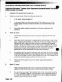
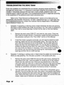
ELECTRICAL TROUBLESHOOnNG: WP·, POWER SUPPLY
II.
Symptom: The console powers up but blanks out while someone is exercising.
A.
Verify both the AC and the DC power.
The problem may be a loose connection or a bad cable. Verify the power as
outlined in the previous "Troubleshooting" section of this Manual. Just moving
the cables and the connections during the tests may pinpoint the problem.
B.
Check for excessive voltage drop.
If the AC and the DC power tests produce positive results. the problem is either
an inoperable power supply or an inoperable console.
1.
Remove the DC power connector cap from the unused connector located
just inside the side cover. Use a DC voltmeter to check the pins on the DC
power connector inside the cover. Pin 11 is positive and pin #2 is negative.
2.
If there are less than 8VDC at the connector. then either the power supply
or the console is inoperable. Continue testing at step 3. If the reading is
between 8-14 VDC. call the Customer Service Department of StairMasteril>
Sports/Medical Products. Inc. for additional assistance.
3.
Replace or exchange the power supply and repeat step 1. If the problem
still exists. go to step 4.
4.
Replace or exchange the console and repeat step 1. If the problem still
exists. call the Customer Service Department of StairMaster
Sports/Medical Products. Inc.
•
A.
B.
ELECTRICAL TROUBLESHOOTING: WP-1 POWER SUPPLY
Symptom: The speed (RPMl feedback is either erratic or wrong.
Perform a visual check.
1.
Remove the neck covers (3000 CE'" only) and the side covers. Do not
disconnect the DC power cable from the connector on the frame.
2.
Make sure the main cable and hall effect sensor wires are connected
(refer to Wiring Diagrams 2 and 3).
3.
Check the clearance between the hall effect sensor and the magnet
mount. The maximum clearance is 1/4" (0.6 em); ensure the magnet mount
does not contact anything as the fan shaft rotates.
4.
Hold the fans and try to turn the magnet mount with your free hand. If the
magnet mount turns on the fan shaft, tighten the magnet mount bolts.
Verify the AC and the DC power.
The problem may be a loose connection or a bad cable. Verify the power as
M
outlined in the first MTroubleshooting section of this Manual. Just moving the
cables and the connections during the tests may pinpoint the problem.
C.
•
Check the hall effect sensor circuits.
1.
Disconnect the plastic connector at the junction of the wires from the
hall effect sensor and the main cable wires (refer to Wiring Diagram 3).
Use a DC voltmeter to check the VDC at the main cable connector. Pin #1
(the red wire) is negative and pin (the orange wire) is positive. The
reading should range between 4.8-5.2 VDC. If it does not, proceed to step
2. If the VDC is within the range, go to step 3.
2.
If the VDC reading is outside the specified range, check for continuity in
the main cable (refer to Wiring Diagram 3).
• Unplug the power supply from the AC wall outlet.
• Unscrew the main cable from the back of the console.
• Place one lead of the multimeter at the console connector
end of the cable and place the other lead at the main
cable connector to the hall effect sensor wires (the
connector you disconnected in step 1).
• Set the multimeter to the continuity check mode; on most
meters this will be the resistance or ohms setting.
• Check for continuity through the main cable at pins #1 (the
red wirel, #3 (the green wire) and #4 (the orange wire).
• If there is continuity through the cable (the reading is near
Peg. 33
ELECTRICAL TROUBLESHOOTING: WP-1 POWER SUPPLY
zero ohms} the cable is good and the console must be
replaced. If there is no continuity through the main cable
at any of the pins, replace the cable.
3.
If the vac reading is within the specified range, check for continuity in the
main cable at pin 13 (refer to Wiring Diagram 3).
• Unplug the power supply from the AC wall outlet.
• Unscrew the main cable from the back of the console.
• Place one lead of the multimeter at the console connector
end of the cable at pin #3 (the green wire) and place the
other lead at the green wire on the main cable connector
to the hall effect sensors wires (the connector you
disconnected in step 1).
• Set the multimeter to the continuity check mode; on most
meters this will be the resistance or ohms setting.
• If continuity exists through the cable (the reading is near
zero ohms), the cable is good and you should proceed to
step 4. If continuity does not exist hrough the main
cable, replace the cable.
4.
Page 34
Plug the power supply into the AC wall outlet. Reconnect the plastic
connector at the hall effect sensor and the main cable wire junction.
Chec the power at the connector by inserting the voltmeter probes into
the connector (at the hall effect sensor side) at pin #1 (the black wire) is
negative and pin #4 (the red wire) is positive (refer to Wiring Diagram 2).
The reading should be between 4.8 and 5.2 VDC. If the reading is withi
the specified range, replace either the console or the hall effect sensr
the reading is outside the recommended range, replace the hall effect
sensor.
ELECTRICAL TROUBLESHOOTING: SERIAUY-UNKED SPINNAKERS
&Ple Spinnaker'" Systems Cycle Ergometers Serially Linked For The Group
Racing Option
I.
Symptom: One (or more) Spinnaker systems cycle ergometer does not power up.
(These power tests will also work on serially linked Spinnaker cycle ergometers
which are operated outside the United States. Canada. and Japan.)
A.
Perform a visual check. Check the following things first:
B.
•
C.
1.
Is the power supply plugged in?
2.
Is the green light lit on the power supply? If the light is not on. is the
power supply switched on and/or does the circuit breaker need to be
reset?
3.
Are all the cables. power and serial. properly connected to the power
supply and to the machines?
4.
While the console is in the AnRACT mode. press [UPARRowl. [11. 171. [41. [61.
[ENTER] and verify the addresses of all the serially linked bikes. Each
console must have a ~nique address number within the range #1 to #5.
Isolate and test the inoperable Spinnaker 3000 CE~ Cycle Ergometer.
1.
Disconnect all serial cables from the inoperable Spinnaker systems cycle
ergometer and connect the power supply directly to that machine. If the
console does not power up. perform the power tests as outlined in
sections Cand D. These tests will identify the inoperable component.
2.
If the console does power up. use a serial cable to connect this machine to
another bike. Continue connecting additional bikes until the original bike
fails. Use a multimeter to check for continuity through the serial cables (at
all three pins) coming out of and going into the last bike that passed the
test (refer to Wiring Diagram 4). Replace the inoperable cable{s).
3.
If there is continuity through the serial cables. the power supply is
probably inoperable. Replace or exchange the power supply and retest.
4.
If the problem still exists. contact the Customer Service Department of
StairMaster Sports/Medical Products. Inc.
Verify AC power.
1.
Disconnect the AC power cord from the power supply and the AC wall
outlet.
Page 35
ELECTRICAL TROUBLESHOOTING: SERIALLY-LINKED SPINNAKERS
D.
2.
Verify that he AC wall outlet is supplying the correct power in one of ~
ways: a) Use an AC voltmeter to verify tha he AC line vol age is between
100 and 120 VAC (or be een 220 and 240 VAC, i applicable) at the AC
wall outlet; or b) Plug in an alterna e AC-powered device (a lamp, for
example). If the AC wall outlet is supplying the correc pwer, go to s ep
13. If the voltage is outside the specified range or if the device does not
work when plugged into the all outlet, consult an electrician for further
assistance and then retest he outle .
3.
Plug the AC cord into the AC wall ou let and verify that the AC line voltage
is between 100 and 120 VAC (or between 220 and 240 VAC, if applicable)
at the opposite end of the cord. Go to step #4 if the AC line voltage is
wi in ange. Replace the cord if the voltage is not wi hin the specified
range and then tes he new cord.
4.
Reconnec he AC power cord to the po er supply and proceed to
section D.
Verify DC power.
1.
Ma e sure that the AC power cord is properly connected to the power
supply and that the AC wall outlet is delivering the proper voltage.
2.
Turn on the power supply. The indicator ligh on the front panel should be
lit. If it is, proceed to step 3. If the indicator is not lit when the switch is
on, reset the circuit brea er. If he light is still no lit, replace the power
supply and test he new power supply.
3.
Disconnect the DC cable from the power supply. Use a DC voltmeter to
verify he DC powe at the DC connector on the power supply front panel
(refer 0 Wiring Diagram 5). Pin 1 is positive and pin 12 is negative. The
voltage should range between 10 and 16 VDC. If it does, go to s ep 4.
Replace the power supply if he DC voltage is not within the specified
range and test the new power supply.
4.
Reconnect the DC cable 0 the power supply front panel. Disconnect the
cable from the DC power connector located just inside the side cover. Use
a DC voltmeter to verify 10-16 VDC at his end of he cable. Pin 1 is
positive and pin 2 is negative (refer to Wiring Diagram 5). If the VDC is
within range, go to step 15. Replace the DC cable if the VDC is outside the
specified range and tes he new DC cable.
5.
Remove he console. Unscre
console.
Peg. 36
he main cable rom the back of he
•
ELECTRICAL TROUBLESHOOTING: SERIALLY LINKED SPINNAKERS
6.
Reconnect the DC cord from the power supply to the DC connector just
inside of the side cover. Use a DC voltmeter to verify 10-15 VDC at the
main cable connector. Pin 2 is negative and pin #9 is positive (refer to
Wiring Diagram 3). If you have no power at pins 2 and #9, check pins #1
(negative) and #8 (positive). The correct pin combination depends on which
side the power supply is connected. Getting the correct reading, not the
pin combination, is the issue.
If the VDC reading is outside the specified range, replace the main
cable and then retest the cable at the connector. If the power is within the
specified range the console is probably inoperable and must be replaced.
7.
If the problem still exists, contac the Customer Service Department of
StairMaste~ Sports/Medical Products, Inc. for further assistance.
•
P.ge 31
ELECTRICAL TROUBLESHOOTING: IPS-3 POWER SUPPLY
Single-Use Spinnlker" Systems Cycle Ergometers Operated Outside The unit.
States. Clnldl. Ind Jlpln
I.
Symptom: The console fails to power up.
A.
Perform a visual check. Check the following things first:
B.
C.
1.
Is the power supply plugged in?
2.
Is the green light lit on the power supply? If the light is not on, is the
power supply switched on and/or does the circuit breaker need to be
reset?
3.
Are all the cables properly connected to the power supply and the
machine?
Verify AC power.
1.
Disconnect the AC power cord from the power supply and the AC wall
outlet.
2.
Verify that the AC wall outlet is supplying the correct power in one of two
ways: a) Use an AC voltmeter to verify that the AC line voltage is between
220 and 240 VAC at the AC outlet; b) Plug in an alternate AC·powered
device (a lamp, for example). If the AC wall outle is supplying the correct
power, to to step 13. If the voltage is outside the specified range or if the
device does not work when plugged into the wall outlet, consult an
electrician for further assistance and then retest the outlet.
3.
Plug the AC cord into the AC wall outlet and verify that the AC line voltage
is between 220 and 240 VAC at the opposite end of the cord. Go to step #4
if the AC line voltage is within range. Replace the cord if the voltage is not
within the specified range and then test the new cord.
4.
Reconnect the AC power cord to the power supply and proceed to
section C.
Verify DC power.
1.
Make sure that the AC power cord is properly connected to the power
supply and that the AC wall outlet is delivering the proper voltage.
2.
Turn on the power supply. The indicator light on the front panel should be
lit. If it is, proceed to step #3. If the indicator is not lit when the switch is
on, reset the circuit breaker. If the light is still not lit. replace the power
supply and test the new power supply.
Peg. 38
.3.
,
ELECTRICAL TROUBLESHOOTING: IPS-3 POWER SUPPLY
Disconnect he DC cable from the power supply. Use a DC voltmeter to
verify the DC power at the DC connector on the power supply front panel
(refer to Wiring Diagram 5). Pin 1 is positive and pin 2 is negative. The
voltage should range between 10 and 16 VDC. If it does. go to step 4.
Replace the power supply if the DC voltage is not within the specified
range and test the new power supply.
4.
Reconnect the DC cable to the power supply front panel. Disconnect the
cable from the DC power connector located just inside the side cover. Use
a DC voltmeter to verify 10-16 VDC at this end of the cable. Pin 1 is
positive and pin 2 is negative (refer to Wiring Diagram 5). If the VDC is
within range, go to step 5. Replace the DC cable if the VDC is outside the
specified range and test the new DC cable.
5.
Remove the console. Unscrew the main cable from the back of the
console.
6.
Reconnect the DC cord from the power supply to the DC connector just
inside of the side cover. Use a DC voltmeter to verify 10-16 VDC at the
main cable connector. Pin 1 is negative and pin #B is positive (refer to
Wiring Diagram 3). If the VDC reading is outside the specified range,
replace the main cable and then retest the cable at the connector. If the
power is within the specified range the console is inoperable and must be
replaced.
7.
If the problem still exists, contact the Customer Service Department of
StairMaste Sports/Medical Products, Inc. for further assistance.
Symptom: The console powers up but blanks out during exercise.
Perform the tests as outlined for Symptom II in the "Electrical Troubleshooting:
WP-1 Power Supply" section. The procedures are the same regardless of the AC
power supply.
III.
Symptom: The speed or RPM feedback is either erratic or wrong.
Perform the tests as outlined for Symptom III in the "Electrical Troubleshooting:
WP-1 Power Supply" section. The procedures are the same regardless of the AC
power supply.
Page 39
CONSOLE DIAGNOSnC TESTS
a
P
The following tests must be performed while the console is in the DIAGNOSTIC mode.
activate the DIAGNOSTIC mode, press the [up ARROW), [1 I. [01. (7). [ENTER). If the console
fails any test, the console should be replaced or exchanged.
Display Test
Use this test if the console display or the text bar exhibits blank spots during use. This
test checks for inoperable light emitting diodes (LEOs) in the console display and the text
bar. If.any LEO will not light. replace the console.
1.
Press (0) to start the test.
2.
All LEOs in the console display should be lit. The 26 alpha characters (A-Zl and 10
numeric characters (0-9) will scroll across the text bar.
3.
Press [CLEAR) to end the test.
Speaker Test
Use this test to make sure the console speaker is fully operational. The speaker will
ascend and then descend through the musical scale.
1.
Press [1) to start the test.
2.
Press [ENTER) to pause the test. Press [CLEAR] to end the test.
KeypadTm
Perform this test if you are having trouble entering data into the console. If you cannot
enter the DIAGNOSTIC mode code due to an inoperable keypad, replace the console.
1.
Press (2) to start the test.
2.
The display LEOs will light up in an L-shaped formation, representing the keypad
matrix. Pressing a button on either the exercise program keypad or the function
keypad will light an LEO within the outline on the display that corresponds to that
button's position on the console.
3.
Firmly press each button. If the LEO corresponding to the button you pushed does
not light up. the keypad is bad and the console must be replaced.
4.
Pressing the [CLEAR) button will light that LEO and then end the keypad test 10
seconds later.
CONSOLE DIAGNOSTIC TESTS
•
Test
This test makes sure the hall effect sensor is sending a pulse to the console. If you want
to verify the console rpm reading, count the crank revolutions while pedaling during the
tach test and compare your count to the RPM displayed in the text bar.
1.
Press [3] to start the test.
2.
The text bar will display the pedal rpm continuously if the hall effect sensor is
working properly. Refer to the appropriate troubleshooting section if the RPM
feedback is either wrong or erratic.
3.
Press [CLEAR] to end the test.
Software Revision Level Test
This test allows you to check the version number of the software installed in the console.
1.
Press [4] to start the test.
2.
The software version number will scroll across the text bar. The console will
automatically return to the ATTRACT mode.
3.
Contact the Customer Service Department of StairMaster*Sports/Medical
Products, Inc. for the most current software revision updates.
•
Paga 41
TROUBLESHOOnNG THE ORNE TRAIN
Drive train problems are manifested first as unusual. annoying noises and then by •
damaged and seized parts. It is important to accurately diagnose the problem and quickly
remedy it. Fortunately, because the drive train is fairly simple, problems with it are
relatively easy to identify and repair. This troubleshooting section is organized according
to the symptoms of the problems which most commonly occur.
Refer to the "Parts Removal and Replacement" section of this Manual for any
disassembly and assembly instructions. To order a replacement part, or to get help with
the troubleshooting process, contact the Customer Service Department of StairMaste~
Sports/Medical Products, Inc.
I.
II.
Symptom: A squealing or whining noise is heard whenever the fans are spinning;
the noise is heard whether the cranks are turning or not. This noise is caused by a
loose Poly-V belt or seized bearings in either the fan shaft or the intermediate
shaft.
1.
Remove the neck covers (3000 CE· only) and the side covers. Check the
Poly-V belt for proper tension. If necessary, tighten the belt according to
the procedure outlined in the "Poly-V Belt" section of this Manual.
2.
If the Poly-V belt is properly tensioned, you will need to check the shaft
bearings. Watch the fan and intermediate shafts. The noise may be in
sync with the revolutions of one of the shafts. The fan shaft spins at a
faster rate than the intermediate shaft. You may be able to isolate the
problem by observing how often the noise occurs. Check the bearings in
the noisy shaft and replace if necessary. If the noise cannot be isolated in
this manner, start by removing and checking the intermediate shaft
bearings and then the fan shaft bearings.
Symptom: A clunking or clicking noise is heard when the pedals are turned but not
when you stop pedaling. This indicates a problem in the pedal/crank area.
1.
Remove the neck covers (3000 CE only) and the side covers. Examine the
area around the chain, crank and pedals for anything out of the ordinary.
Slowly turn the crank and see if there are any obstructions in the drive
train area. Hold one crank arm in each hand. Rock the crank back and forth
to detect excess play or looseness in the crank bearings. Readjust the
bearing nut assemblies and tighten the bearing clamps if necessary.
2.
Turn the cranks and listen for the noise. If the noise is still present, go to
step 113. If you do not hear the noise, the cranks or the pedals were hitting
the covers. Examine the side covers near the crank cutout for evidence of
wear. Verify that both crank arms are straight. When you reinstall the side
covers, make sure all fasteners are properly installed.
Page 42
•
III.
TROUBLESHOOTING THE DRIVE TRAIN
3.
Remove the drive chain. Spin the crank. If the noise is still present. go to
step 4. If you do not hear the noise. reinstall the drive chain and check
the chain alignment between the chainring and the freewheel. If the noise
is still present and the drive chain is properly aligned. replace the drive
chain.
4.
Remove both pedals from the crank. Spin the crank. If the noise is still
present. go to step 15. If you do not hear the noise. the pedal spindle
bearings may be worn out. To check the bearings. hold a pedal in one hand
and rotate the pedal spindle with the other hand. If the spindle is hard to
turn or if you detect rough spots as you rotate the spindle. replace the
pedal. Repeat this procedure with the other pedal.
5.
Check the bearing clamps. If the allen bolts are loose. tighten them and
spin the crank. If the noise is still present. readjust the bearing nut
assemblies and spin the crank. Remove the crank assembly from the frame
if the noise is still present. Check the right and left bearing nut assemblies
for smoothness of operation. Replace the bearing nut assembly if
necessary.
Symptom: A clunking or clicking noise is heard while the fans spin and the crank
is stationary. This noise indicates a problem in the drive reduction train.
1.
Remove the neck covers (3000 CE'" only) and the side covers. Examine the
area around the flywheel and the Poly-V pulley for anything out of the
ordinary. Slowly turn the crank and see if there are any obstructions in the
drive reduction area.
If the Poly-V belt is properly tensioned. you will need to check the shaft
bearings. Watch the fan and intermediate shafts. The noise may be in
sync with the revolutions of one of the shafts. The fan shaft spins at a
faster rate than the inermediate shaft. you may be able to isolate the
problem by observing how often the noise occurs. Check the bearings in
the noisy shaft and replace if necessary.lf the noise cannot be isolated in
this manner. start by removing and checking the intermediate shaft
bearings and then the fan shaft bearings.
3.
Remove both fans and check the pillow block bearing set screws. They
should be snug. Check the nut on the left end of the intermediate shaft; it
should also be tight. Reinstall the fans. spin them and listen for noise. If
the noise is still present. go to step #4.
4.
Remove the intermediate shaft assembly and the fan shaft assembly.
Inspect the fan shaft bearings for smoothness of operation. Replace the
bearings if necessary.
Page 43
TROUBLESHOOnNG THE DRIVE TRAIN
5.
Remove the intermediate shaft from the Poly-V pulley. Inspect the
intermediate shaft bearings for smoothness of operation. Replace the
bearings if necessary.
6.
Check the freewheel for smoothness of operation in the counterclockwise
direction and positive engagement in the clockwise direction. If the
freewheel sticks. or fails to engage. replace it.
7.
Reassemble the drive train. Turn the crank; if the noise is still present call
the Customer Service Department of StairMaster Sports/Medical
Products. Inc. for further assistance.
PARTS REMOVAL AND REPLACEMENT
3000 CE
The Spinnaker"' 3000 CE" cycle ergometer is protected by four plastic covers: two large
side covers and two smaller neck covers. Refer to Figure 6 for the fastener locations.
1.
The neck covers are held in place with six screws: one on each side. two on the
front. and two on the rear. The neck covers must be removed before the side
covers are removed.
2.
Disconnect the DC power cable from the connector located just inside the bottom
front corner of the side cover.
3.
The side covers are held in place with four reusable fasteners. Slide either end of
the fastener removal tool under the edge of the pin head and pull the pin out
about halfway (refer to Figure 9). The pin should not be pulled out of the base.
4.
After the fasteners have been removed, lift the square rubber grommet away from
the base of the seat post.
5.
Move the crank to about the eleven o'clock position on the right side to get the
right side cover over the crank. Once the right cover is off the frame. move the
cranks to the one o'clock position on the left side and remove the left cover.
6.
When reinstalling the side covers. feed the connector caps and chains through the
holes in the side covers. To reinstall the fastener. insert the base of the fastener
through the cover and into the frame. When the base is in place. push the pin in
all the way to secure the fastener. Connect the DC power cable to the power
connector once the side covers are in place.
•
3600 HC
The Spinnaker 3600 RC~ cycle ergometer is protected by two plastic side covers. Refer to
Figure 7 for the fastener locations.
1.
Disconnect the DC power cable from the connector located just inside the bottom
rear corner of the side cover.
2.
The side covers are held in place with five reusable fasteners. Slide either end of
the fastener removal tool under the edge of the pin head and pull the pin out
about halfway (refer to Figure 9). The pin should not be pulled out of the base.
3.
After the fasteners have been removed. lift the neck grommet away from the
covers.
P.ge f5
PARTS REMOVAL AND REPLACEMENT
t.
4.
Move the crank to about the eleven o'clock position on the right side to get
right side cover over the crank. Once the right cover is off the frame. move the
cranks to the one o'clock position on the left side and remove the left cover.
5.
When reinstalling the side covers, feed the connector caps and chains through the
holes in the side covers. To reinstall the fastener. reinsert the base of the fastener
through the cover and into the frame. When the base is in place. push the pin in
all the way to secure the fastener.
CONSOLE
1.
Disconnect the DC power cable from the connector loca ed just inside the side
cover.
2.
Remove the neck covers (3000 CE'" only).
3.
Remove the four mounting bolts and associated hardware from the back of the
console.
4.
Unscrew the main cable connector from the back of the console.
5.
Reverse the steps to reinstall the console.
HANDLEBAR/CONSOLE MOUNTING TUBE
3000 CE
1.
Remove the console.
2.
Loosen and remove the two nyloc nuts and flat washers from the mounting bolts
(refer to Figure lO).
3.
Remove the mounting bol s from the frame tube.
4.
Hold onto the handlebar with both hands and remove the handlebar/console
mounting tube from the frame tube. You may have to twist the handlebar/console
mounting tube as you pull up on the handlebar.
5.
Reinstall in the reverse order.
1.
Remove the console.
2.
Loosen and remove the four nyloc nuts from the mounting flange (refer to
Figure 12).
Page 46
•
PARTS REMOVAL AND REPLACEMENT
3.
Remove the mounting bolts and flat washers from the frame.
4.
Hold onto the handlebar with both hands and lift the handlebar/console mount off
the frame.
5.
Reinstall in reverse order.
SEAT
3000 CE"'
1.
Loosen and remove the four moun ing bolts and lock washers loca ed underneath
the seat (refer to Figure 11).
2.
To reinstall the seat, line up the holes in the seat post mounting tab with the
holes in the seat. Insert one bolt with a lock washer into each hole and tighten
securely.
3600 RC
The seat pads can be removed while he seat is in the seat track. Loosen and remove the
four mounting bolts from each seat pad and lift the pad free. To remove the seat from the
sea track:
1.
•
Loosen and remo e he nyloc nut from he rear of the seat track. Remove the
bolt.
Remove the seat track cover.
3.
Lift the seat adjustment handle and slide the seat to the rear and off the track.
4.
To reinstall he seat, line up the front guide wheels with the seat track.
Carefully slide the sea forward while holding up on the seat adjustment
handle.
5.
Install the seat track cover.
6.
Install the bolt and nyloc nut. Securely tighten the nut.
7.
The seat track play can be adjusted. Loosen the nut on both center wheels. Use
a standard screwdriver to turn the bolt. Ideally, the seat should slide easily
without excessive side play. Tigh en the nu s after the wheels are adjusted.
Page 47
PARTS REMOVAL AND REPLACEMENT
SEAT LOCATION POST (3000 CE ONLY)
•
1.
Pull the seat adjustment knob out and raise the seat.
2.
Insert a phillips screwdriver into one of the holes in the seat post which are
located above the seat tube cap (refer to Figure 11). Gently lower the seat so that
the seat is held up by the screwdriver. The seat adjustment shaft will be protruding slightly because the shaft is between the holes in the seat post.
3.
Hold the seat adjustment shaft with a pair of locking pliers and remove the seat
location knob from the shaft by turning the knob counterclockwise.
4.
Remove the screwdriver from the hole in the seat post and lower the seat slightly
so the seat adjustment shaft engages a hole in the seat post. This will reduce the
tension in the spring return mechanism.
it
WARNING
TO REDUCE THE RISK OF EYE INJURY. WEAR EYE PROTECTION WHEN REMOVING
SNAP RINGS.
5.
Remove the outermost snap ring.
6.
Unweight the seat post by applying a slight upward force to the bottom of the
seat.
7.
Pullout the seat adjustment shaft. removing both washers and the spring at the
same time.
8.
Insert a phillips screwdriver into one of the holes in the seat post which are
located above the seat tube cap. Remove the snap ring located in front of the seat
selector bushing.
9.
Remove the two screws securing the seat tube cap to the frame.
10.
Remove the screwdriver from the seat post. Raise the seat tube cap up and away
from the frame.
11.
Push the seat location post forward so the seat adjustment bushing is moved
slightly forward in the bushing housing.
12.
Insert a standard screwdriver between the seat post and the seat adjustment
bushing and gently pry the bushing farther out of the bushing housing and out of
the way of the nylon seat post guides.
P.,. 48
•
14.
PARTS REMOVAL AND REPLACEMENT
Remove the grommets from the holes in the seat tube. Pull the seat post up and
out of the frame.
Reverse the steps to reinstall the seat post in the frame.
SEAT TRAY (3600 RC
TII
ONLY)
1.
Remove the right side cover.
2.
Remove the seat.
3.
Loosen and remove the three nyloc nuts, bolts and flat washers that fasten the
seat tray to the frame (refer to Figure 13).
4.
Reverse the steps to reinstall the seat tray.
DRIVE CHAIN
1.
Remove both neck covers (3000 CE™ only) and the right side cover.
2.
Slowly rotate the right pedal. As the chain rotates, locate the master link.
3.
Remove the master link retaining plate with a standard screwdriver. Use the flat
of the screwdriver to push the retaining plate off the pins.
4.
Remove the master link from both ends of the chain. Remove the chain from the
chainring and freewheel.
•
Reverse the steps to install the chain. Ensure that the closed end of the master
link retaining plate is facing the direction of chain travel.
6.
Check the tension in the drive chain. There should be 1/2· (1 em) of up and down
travel for a total of 1· (2 em) in the middle of the lower section of the drive chain
(refer to Figure 16).
7.
To adjust the chain tension, loosen the nuts at the top and the bottom of the
intermediate shaft bracket. Pivot the brackets as needed to get the proper chain
tension. Tighten the nuts and recheck the chain tension. Readjust the chain if
necessary.
8.
Reinstall the covers.
PARTS REMOVAL AND REPLACEMENT
FAN
lM
•
1.
Remove both neck covers (3000 CE only) and the side covers.
2.
The fan is attached to the fan shaft with an allen-head set screw. Slowly spin the
fans and find the small cutout located along the outside edge of the fan. directly
above the set screw. Use a T-handled allen wrench to loosen the set screw.
3.
Slide the fan off the fan shaft.
4.
Reverse the steps to reinstall the fan. Make sure the set screw in the fan bushing
makes contact with the flat section of the fan shaft.
5.
If you remove both fans. remember that the larger-diameter fan goes on the right
side of the fan shaft. The fan blades should be facing the direction of rotation.
The fans are marked with directional arrows.
INTERMEDIATE SHAFT ASSEMBLY/POLY-V BELT/POLY-V PULLEY/FREEWHEEL
1.
Remove both neck covers (3000 CE only) and the side covers.
2.
Remove both fans.
3.
Remove the drive chain.
4.
Loosen. but do not remove. the nuts at the top and bottom of the intermidiate
shaft bracket (refer to Figure 19).
5.
Loosen the j-bolt nut so the Poly-V belt is slack.
6.
Loosen the mounting nut and remove the magnet mount from the left side of the
fan shaft.
7.
Loosen the pillow block bearing set screws on the left side fan shaft bracket (refer
to Figure 17).
8.
Loosen and remove the hall effect sensor mounting nuts and screws. Cut the
tywrap that holds the sensor cable to the left side fan shaft bracket. Set the hall
effect sensor to the side.
9.
Support the flywheel and remove the two bolts from the threaded spacer.
Carefully lower the flywheel onto the Poly-V pulley.
10.
Support the intermediate shaft bracket and remove the nut and bolt from the top
of the intermediate shaft bracket. Lean the intermediate shaft bracket out of the
way.
Page 50
PARTS REMOVAL AND REPLACEMENT
Hold onto the flywheel and slide the left side fan shaft bracket off the fan shaft.
12.
Slide the Poly-V belt off the flywheel. Remove the right side fan shaft bracket and
flywheel. as a unit, from the frame.
13.
Loosen and remove the nut from the left side of the intermediate shaft. Pull the
intermediate shaft out of the intermediate shaft bracket.
14.
Remove the Poly-V pulley and Poly-V belt from the intermediate shaft bracket.
15.
Inspect the intermediate shaft bearings (they are inside the Poly-V pulley) for
smoothness of operation. Replace the bearings if necessary.
16.
Inspect the freewheel for smoothness of operation in the counterclockwise
direction and for positive engagement in the clockwise direction. Use a freewheel
tool to remove the freewheel from the Poly-V pulley, if replacement is necessary.
17.
Reverse the steps to reinstall the parts. Additionally, ensure that:
• The short side of the j-bolt hook faces to the rear of the frame.
• The wider portion of the threaded spacer faces to the right.
• You use a new tywrap on the sensor cable and the left side fan shaft bracket.
Ensure the wires are fully seated in the white plastic connector.
• The magnet mount is as close to the hall effect sensor as it can get while
not contacting the hall effect sensor as the fan shaft turns. The magnet mount
can be up to 1/4 inch (0.6 cm) away from the hall effect sensor.
• The fans are installed according to the instructions in the "Fan" section
of the Manual.
• The drive chain is adjusted according to the procedure outlined in the "Drive
Chain" section of this Manual.
• The Poly-V belt is adjusted so the distance between the edges of the top and
bottom spring retainers on the j-bolt is between 1-7/16 and 1-9/16 inches
(3.7 - 4.0 cm) (refer to Figure 18).
FAN SHAFT ASSEMBLY
N
1.
Remove both nec covers (3000 CE only) and the side covers.
2.
Remove both fans.
3.
Remove the drive chain.
4.
Loosen, but do not remove, the nuts at the top and bottom of the intermediate
shaft bracket (refer 0 Figure 19).
5.
Loosen the j-bolt nut so the Poly-V belt IS slack.
Page 51
PARTS REMOVAL AND REPLACEMENT
o.
6.
Loosen the mounting nut and remove the magnet mount from the left side
fan shaft.
7.
Loosen the four pillow block bearing set screws on the right and left side fan
shaft brackets (refer to Figure 17).
8.
Loosen and remove the hall effect sensor mounting nuts and screws. Cut the
tywrap that holds the sensor cable to the left side fan shaft bracket. Set the hall
effect sensor to the side.
9.
Support the flywheel and remove the two bolts from the threaded spacer.
Carefully lower the flywheel onto the Poly-V pulley.
10.
Support the intermediate shaft bracket and remove the nut and bolt from the top
of the intermediate shaft bracket. Lean the intermediate shaft bracket out of the
way.
11.
Hold onto the flywheel and slide the left side fan shaft bracket off the fan shaft.
12.
Slide the Poly-V belt off the flywheel. Remove the right side fan shaft bracket and
flywheel, as a unit. from the frame.
13.
Remove the right side fan shaft bracket from the fan shaft once the assembly is
away from the frame.
14.
Inspect the pillow block bearings for smoothness of operation. The pillow block
bearing assemblies can be removed from the fan shaft brakcets by lOOSening.
removing the two jamnuts, lock washers, and screws.
15.
Reverse the steps to reinstall the fan shaft assembly. Additionally, ensure that:
• The short side of the j-bolt hook faces to the rear of the frame.
• The wider portion of the threaded spacer faces to the right.
• You use a new tywrap on the sensor cable and the left side fan shaft bracket.
Ensure the wires are fully seated in the white plastic connector.
• The magnet mount is as close to the hall effect sensor as it can get while
not contacting the hall effect sensor as the fan shaft turns. The magnet mount
can be up to 1/4 inch (0.6 cm) away from the hall effect sensor.
• The fans are installed according to instructions in the "Fan" section of
the Manual.
• The drive chain is adjusted according to the procedure outlined in the "Drive
Chain" section of this Manual.
• The Poly-V belt is adjusted so the distance between the edges of the top and
bottom spring retainers on the j-bolt is between 1-7/16 and 1-9/16 inches
(3.7 - 4.0 cm) (refer to Rgure 18).
".". 52
PARTS REMOVAL AND REPLACEMENT
1.
Use a 15-mm pedal wrench or a 5/S" open end wrench to loosen and remove the
pedals from the crank.
2.
The pedal on the left side of the crank has reverse threads. Turn the wrench on
the left pedal clockwise to loosen it. Turn the wrench on the right pedal counterclockwise to loosen it.
3.
Apply a small amount of multi-purpose grease to the threads of the pedal spindle
before reinstalling the pedals on the crank.
4.
The left pedal spindle is marked with an "L" and the right pedal spindle with
an ~R.·
CRANK AND BOTTOM BRACKET ASSEMBLY
1Io4
1.
Remove both neck covers (3000 CE only) and the side covers.
2.
Remove the drive chain.
3.
Remove the left pedal.
4.
Loosen and remove the bottom bracket jam nut located on the left side of the
crank (refer to Figure 20). This nut has reverse threads; loosen it by turning it
clockwise.
•
Remove the round. plastic crank shield from the left side of the crank.
6.
Remove the bearing clamps by loosening the allen bolts from'the left side clamp.
7.
Loosen and remove the left bearing nut assembly. This nut has reverse threads;
loosen it by turning it clockwise.
S.
Slide the crank out of the frame to the right.
9.
The right bearing nut assembly can be removed from the crank with a 32-mm cone
wrench. The right bearing nut assembly also holds the chainring in place on the
crank. If the chainring is damaged. replace it now.
10.
Inspect the bearings for smoothness of operation. Replace the bearings if
necessary.
11.
Ensure that the right bearing nut assembly is tight against the chainring before
reinstalling the crank into the frame.
P.g. 53
PARTS REMOVAL AND REPLACEMENT
12.
Install the left bearing nut assembly onto the crank and tighten it with a torq
wrench set to 22 inch pounds (2.5 ewton meters). Do not overtighten the nut;
the crank should spin freely.
13.
Install both bearing clamps and tighten the allen bolts. Do not overtighten the
allen bolts; the cran should spin freely.
Install the round, plastic crank shield, the jam nut and the pedal onto the left side
of the crank. Remember, the jam nut and the pedal have reverse threads (tigh en
them in the counterclockwise direction).
14.
15.
Adjust the side play in the crank by tightening or loosening the left side bearing
nut with a 32-mm cone wrench. The crank should spin freely without binding.
When the crank is properly adjusted, hold the left side bearing nut with the cone
wrench and tighten the jam nut securely. Recheck the crank adjustment after
you've tightened the jam nut.
16.
Install the drive chain and the side and neck covers.
Page 54
GROUNDING INSTRUCnONS
tairMaster" Spinnaker"' systems cycle ergometer must be grounded. If it should
malfunction or break down, grounding provides the path of least resistance for the
electric current, thereby reducing the risk of electric shock. This machine is equipped with
a cord having an equipment-grounding conductor and a grounding plug. The plug must be
plugged into an appropriate outlet that is properly installed and grounded in accordance
with all local codes and ordinances.
it
WARNING
IMPROPER CONNECnON OF THE EQUIPMENT-GROUNDING CONDUCTOR CAN RESULT
I THE RISK OF ELECTRIC SHOCK. CHECK WITH AQUALIFIED ELECTRICIAN
OR SERVICEMAN IF YOU ARE IN DOUBT AS TO WHETHER THE MACHI EIS
PROPERLY GROUNDED. DO NOT MODIFY THE PlUG PROVIDED WITH THIS MACHINE.
IF IT WILL NOT FIT THE AVAILABLE OUTLET, HAVE A PROPER OUTLET INSTALLED BY
A QUALIFIED TECHNICIAN.
The Spinnaker systems cycle ergometer is designed for use on a nominal 120volt circuit, and has a grounding plug that looks like the plug illustrated in sketch A in
Figure 16. * A temporary adapter that looks like the adapter illustrated in sketches Band
Cmay be used to connect this plug to a two-pole receptacle as shown in sketch Bif a
properly grounded outlet is not available. The temporary adapter should be used only
until a properly grounded outlet (sketch Al can be installed by a qualified electrician. The
green colored lug extending from the adapter must be connected to a permanent ground
such as a properly grounded outlet box cover. Whenever an adapter is used, it must be
held in place by a metal screw.
•
* This may vary for International power supplies.
".,)
,
J
_
j
prong at' e
box
C·O. t cd
Ou e
(A)
screw
90034-A
2/22/9~
1.4
Figure 22: Grounding Systems
Page 55
NonCE OF FCC COMPLIANCE
This equipment has been tested and found to comply with the limits for a Class A dig.
device, pursuant to Part 15 of the FCC rules. These limits are designed to provide
reasonable protection against harmful interference when the equipment is operated in a
commercial environment. This equipment generates, uses, and can radiate radio
frequency energy and, if not installed and used in accordance with the instruction
manual. may cause harmful iinterference to radio communications. Operation of
equipment in a residential area may cause harmful interference in which case the user
will be required to correct the interference at his own expense.
it.
WARNING
CHANGES OR MODIFICATIONS TO EQUIPMENT NOT EXPRESSLY APPROVED BY
STAIRMASTER"' SPORTS/MEDICAL PRODUCTS, INC. COULD VOID THE USER'S
AUTHORITY TO OPERATE THIS EQUIPMENT.
CANADIAN DOC CLASS ACOMPUANCE
This digital apparatus does not exceed the Class A limits for radio emissions from digital
apparatus set out in the radio interference regulations of the Canadian Department of
Communications.
La present appareil numerique ne depasse pas les limites etablies pour les bruits
radioelectriques applicables aux appareils numeriques de la Class A prescrites dans les
reglement sur Ie brouillage radioelectrique edicte par Ie Ministere des Communications
du Canada.
•
1'... 56
HOW TO ORDER PARTS
need assistance. please have bo h the serial number of your machine and the date
of purchase available when you contact the appropriate StairMaster Sports/Medical
Products. Inc. office listed below.
OFFlCES IN THE UNITED STATES
CORPORATE HEADQUARTERS
12421 Willows Road NE. Suite 100
Kirkland. WA 98034
(800) 635-2936 or (206) 823-1825
FAX: (206) 823-9490
CUSTOMER SERVICE
12421 Willows Road NE. Suite 100
Kirkland. WA 98034
(800) 331-3578 or (206) 823-1825
FAX: (206) 814-0601
INTERNATIONAL OFFlCES AND DISTRIBUTORS
INTERNATIONAL DIVISIO
(206) 823-1825
FAX: (206) 820-7505
CANADA: TRC SPORTS SYSTEMS
(800) 668-4857
(905) 712-2719
FAX: (905) 712-3722
EUROPE: HEADQUARTERS
41-92-823801
FAX: 41-92-823802
JAPAN: SENOH CORPORATION
81-035479-6711
FAX: 81-035479-6703
GERMANY: HEADQUARTERS
49-2204/610-27
FAX: 49-2204/628-90
AUSTRALIA: THE FITNESS
GENERATIO PTY LTD
61-3/800-2122
FAX: 61-3/800-2722
~: HEADQUARTERS
44-908/221-323
FAX: 44-908/223-162
SWEDEN/NORWAY: ORDIC GYM
PRODUCTIO
46-278/242-10
FAX: 46-278/159-66
FRANCE/BELGIUM:
MONDIAL S.P.R.L.
32-82/226775
FAX: 32-82/226854
COUNTRIES NOT LISTED
(206) 823-1825
FAX: (206)823-7505
Page 57
RGURES
Figure 5: Leve I'mg Adiustment Cap
//
/- ® Leve'"ng
•
odJus
en
cop
o:o'e co
•
Frome
u e
\1007
1/ 6/J
Page 58
p.
,
,
•
RGURES
Figure 6: Power Supplies
Wall mounted
power supply
•
ultiple bike power supply, domestic; PS-6
International power supply; IPS-3
90031-c
...
2/'~
•
RGURES
Figure 7: Cover Fatener Locltion. 3000 CE'"
1. A
001
WI
2. A
0 01 0
six
co e s.
speed
0 r
e side covers.
eck Cover Grom
et 0
ut
si e
2x
94 Con nee or
c.
90111-A
J/02/9~
".
.
1-20
RGURES
•
T ere are a
fos e ers a
Figure 8: Cover Fastener Location. 3600 HC"'
a
01
a
5
he side covers.
•
One
fastener
in front
--- .-
----
90112-A
3/02/15
'-'lO
•
RGURES
Cover Fastener
Fastener Removal Tool
/
99
Fas ener Re
•
oval Tool
90 17-A
J/02/95
1_2
•
RGURES
Figure 10:- Right Side View, 3000 CE
Console/hondleaar
mounting ube
Sea
4x
Seat adju5 ment
'1ob
Freewheel
k-
Link
ainring
90029-C
J/02/8~
1-12
Page 63
,.----------~~-
---
RGURES
Figure 11: Left Side View, 3000 CE
•
Lock Washer. 4x
Magnet !.4ount
Fan Shaft
Brocket
~
n
\b1.;,J:all
Effect
Sensor
Poly-V pulley
90026-C
>I'./'!> '·'2
•
FIGURES
Figure 12: Right Side View, 3600 Re
1 Console
Chain ring
Poly-V Pulley
Cronk
•
Foots rap
Wheel,
Pedal
Free wheel
ain
as er
lin~
90113-A
J/02/9)
1_18
Page 65
•
RGURES
Fig.,. 13: Left Side View. . . RC
Screw, 4x
Lock Washer, 4x
Cop, 4x
Washer, 4x
Flat
Washer,
U,
2x
er, 2x
er, 2x
•
Screw,
Paly-V Bel
Nyloc
Flo
Washer 7
90114-A
J/02/9~
1_20
•
RGURES
Figure 14: Se" Adjustment Pin Assembly, 3000 CE
Sea
45 Seat Adj s men
KnOb Assc
Iy
Sea
Pas
Seal Ad) s mer t
Sot
•
5- ell
be Cop
~i
Sea
Bu.
90023-C
J/D2/9~
1.~
Page 67
•
RGURES
Figure 15: Sat -'-1IIy, . . RC
Seat 46
Bac
COlfer
50 Seat Bottom
I
io
---r"-!-
Flat Washer, ~
4x
-
Washer,
4x~;j
Seat Adjustment Lever 56
Screw, 4x 2
A90115-A
'1./1'/~
Pag. 61
1_1
•
RGURES
Figure 16: Drive Chlin Tension
•
Pege 69
I
•
RGURES
Figure 17: Fel Sheft Assllllbly
,
2X
See detail A
Fan
Spacer
2X
•
DETAIL A
right & left side fan
shaft brocket
90030-C
J/02/9~
Page 70
1.16
•
RGURES
Figure 11: J-bolt Aae_1y
70
J-boll
7
1 7/16
•
3./ -
I
Spring re ciner
1 9/ f)
40 eM
I
spring
90 16-A
2/16/9~
1-2
Page 71
•
RGURES
figure 19: Intenaediete Shaft Aae.bIJ
Was er
Bearing
•
"
Flo
as
"
"
In ermedia e
S oft Brocket
90032-C
J/01/9~
Peg. 12
1_12
FIGURES
Figure 20: Creak Assembly
1 Chain ring
u
Assembly. 2X
Bearing Clomp, 2X
•
90033-B
3/02/95
'.12
P.ge 73
Fig
re 21: Fa. SINdt Asse.bly Cross SectiOI
Threoded Spocer
Fon
Flonge Mounted Bepring
Mount
Fonshoft Brocket
Spocer, 2X
90035-C
J/OJ!"
1.1
WIRING DIAGRAMS
Wiring Di.gram 1: W.II-Mou....dPower Supply
96
VIEW A-A
PI
PI
PI
PI
1-WHITE (POS)
2- LACK ( EG)
3-GREE
4- IC
90016-8
3/D2/9S
'-2
Peg. 15
WIRING DIAGRAMS
Wirillg Diagralll 2: Mai. Cebl. Asse.bly
- EL (POS)
2-BL (EG)
3-G \ VEL (E G D)
4-BR (SER)
VIEW D-D
(Power Con nee or)
I-PUR
2-W T
3-GR \
4 - BLU
(POS)
( EG)
YEL (E G D)
(SERIAL)
4-0RG (POS)
3-GR (REVS)
2- IC
-RED ( EG)
I
VIEW B-B
VIEW C-C
(Power Con ector)
(To Holl Effect Sensor)
C
C
-.J
L
.- ,
A
A
I
~g
"age 16
90020-C
2/15/95
1-.
r
•
WIRING DIAGRAMS
Wirillg Diagram 3: Serial Cable Assembly
PI
PI
PI
PI
-w T
2-BL
3-BR
4-RED
VIEW A-A
•
PI
-WH (POS)
PI
2-BLK ( EG)
PIN 3-BR
(E G D)
PI
4-RED (SERIAL)
90021-8
J/02/9'
'-2
Page 17
WIRING DIAGRAMS
Wiri... DiegrlIB 4: .. D.C. Pow.r C.bl. Assembly
P
PI
98
lJ=u
;:
(~~~
~)
OJ
VIEW A-A
A
A
o .
.J/01/9~
'.ge
18
-A
1-1
r-------.".-: ::::::~:.}·i;{r::.ti~:@1i~~~1\%~
KEY TO FIGURES AND WIRING DIAGRAMS
"'Number
1
2
3
4
5
6
7
8
9
10
11
12
13
14
15
16
17
18
19
20
21
22
23
24
25
26
27
28
29
30
31
32
33
34
:3
Description
Console Assemblv, 3000 CE
Console AssemblY,3600 RC
Lock washer, 1/4"
Screw, 1/4 - 20 x 3/4
FinishilJg cap
FinishinCl washer, 1/4"
Bolt, 3/8 - 16 x 2 3/4
Flat washer, 3/8"
Nyloc nut, 3/8 - 16
Screw, 3/8 - 16 x 2 3/4
Cover fastener
Speed nut
Screw, 18 x 5/8
Neck cover, right, 3000 CE
Neck cover, left, 3000 CE
Side cover, riClht. 3000 CE
Side cover, left, 3000 CE
Side cover, right, 3600 RC
Side cover riaht 3600 RC
Drive chain, 3000 CE
ReadinCl rack, 3000 CE
Footstrao, riqht
Footstrap, left
Pedal. right
Pedal. left
Drive chain, 3600 RC
Master link
Wheel, 3" diameter
Cotter pin
Clevis pin
LevelinCl adiustment cap
Main cable, 3600 RC
Screw, .312 -18 x 1
Flat washer, 1/4"
Nvloc nut, 1/4"
Manin cable, 3000 CE
Polv-V belt
Screw 5/16 - 18 x 2 3/4
Nyloc nut, 5/16"
Grommet 1 1/2" 0.0.
~~~~~
Part Number
24075
21414
22027
22162
22323
22324
22196
22030
22029
24510
22086
24201
22117
24080
24081
24145
24146
24464
24463
24034
24246
24218
24217
24037
24048
24410
24198
24164
22329
22326
24074
24415
22165
22038
22036
24131
24031
24516
22032
24519
4f
77
I~
-".,
,)
.
.-
...
-
-
PII9e 79
KEY TO FIGURES AND WIRING OIAGRAMS
10 Number
35
36
37
38
39
40
41
42
43
44
45
46
47
48
49
50
51
52
53
54
55
56
57
58
59
60
61
63
64
65
66
67
68
69
70
71
72
".,.
.,
Oescriotion
Flat washer
Bolt. 3/8 - 16 x3
Seat track
Seat, 3000 CE
Bolt, 5/16 - 18 x1
Lock washer. 5/16'
Seat oost assemblv
Seat tube cap
Screw. 18 x3/8
Grommet, seat post
Seat adiustment knob assemblv
Seat back cover
Back. seat, 3600 RC
Cap. seat frame
Mid back seat. 3600 RC
Bottom, seat. 3600 RC
Mid back seat cover
Screw. 5/16 - 18 x21/4
Finishina washer .312'
Flat washer. 5/16'
Tapered handle
Adjustment lever
Fan. right side
Fan. left side
Fan set screw
Bolt, 3/8 - 16 x43/4
Bolt, 3/8 - 16 x1 1/2
Flywheel
Threaded spacer
Fan shaft
Fan shaft bracket
Screw. 3/8 -16 xl
Lock washer, 3/8
Jam nut. 3/8 - 16
FlanQe mounted bearinQ
J-bolt. 3000 CE
J-bolt. 3600 RC
Sorina retainer
Valve sprinQ
Part Number
24518
24102
24490
24036
22071
22070
24205
24062
24069
21146
24414
23647
24563
23648
24477
24416
24498
24554
22075
24499
24482
24047
24046
22072
24203
22017
24007-03
24024
24462
24541-03
23851
23729
22228
24531
24317
24428
23760
23758
~
I"-
-~
... "
-
....
-...
I-
.
-
1
r
KEY TO FIGURES AND WIRING DIAGRAMS
,-
Number
73
74
75
76
77
78
79
80
81
82
83
84
85
86
87
88
89
90
91
92
93
94
- 95
96
Descriotion
Polv-V pullev. 12" diameter
Wave washer
BearinQ. 15mm x 35mm
Intermediate shaft
Freewheel 5pro~\
Bearing. 15mm x 28mm
Intermediate shaft bracket
Crank
ChainrinQ
-krlBearing nut a~sembly. right side
Bearina nut assemblv. left side
Bearing clamp. left side
Threaded bearing clamp. right side
Crank shield
Crank iam nut
Screw. #10 - 32
Lock washer. #10
Magnet mount assembly
Hall effP.ct !lP.mOI'
{ " ,....."'JI.AI, ~ ...
.//
Nvlon soacer..63 lana
Screw. #8 - 32 x 1.25
Nut #8 -32
Grommet. cover. 3600 RC
Connector cap
Button plua
1.
Wall-mounted power supplv. WP-1
.
lA"I.;nln_hilc~ nnw~r ~lInnlv
97
98
99
100
101
PS-n
Multiole-bike DOwer suoolv international IPS-3
Serial cable assemblv
DC DOwer cable
Fastener removal tool
Grommet neck cover 3000 CE
Grommet side cover 3000 CE
Part Number
24386
24545
24387
24542
24035
24032
24537-03
24055
24057
24086
24087
24077
24078
24083
24073
24079
24088
--
T-Z4395
14101
./24383
24394 22110
24474
14063
22QB.1.
14051 J
71R71
14072
24099
10841
23853
24221
24214
~
-
~
I-
... ,
~.
...
,