1
HP Channel Services Network
Page 1 of 18
HP LaserJet 9000,9050, 9000mfp, 9040mfp and 9050mfp Series PrintersTWI: Troubleshooting and Resolving 13.20 Paper Jam Error Messages
Introduction
Call Center Agents (Troubleshooting to be performed with customer)
Tools required
Parts required (part numbers are subject to change)
Troubleshooting the cause of the 13.20 errors
13.20 errors caused by Tray 1, Registration or Face Down delivery assemblies
Instructions on replacing the face down delivery assembly
Instructions on replacing the registration assembly
How to resolve a False 13.20 error message - During power up printer never displays CHECKING PAPER PATH on the control panel and
the HVPS has notjust been replaced
Service Note Information
Instructions on replacing the DC Controller
13.20 Errors immediately after service repair for replacement of High Voltage Power Supply (HVPS)
Removal and replacement instructions for 13.20 after service repair for replacement of HVPS
Document number BPL90217
Last updated 16-Oct-2006
Minimum skill level 2
Introduction
This document will assist in troubleshooting 13.20.00 paper jams. Any of the following can cause 13.20 errors.
NOTE:AGENTS: It is critical to identify if the printer displays CHECKING PAPER PATH during power up then goes to a 13.20 error
message or immediately boots straight to a 13.20 error. This determines what is causing the issue and how to resolve it.
Prior to beginning troubleshooting, it is useful to show the event log on the control panel and see what the error is that precedes the 13.20
error. To do this, look at the page count for the 13.20 error, then locate all other errors that share the same page count. In this list of errors
sharing the same page count, the first error is the most important as it is the sensor/assembly that detected a jam that led to a 13.20 error
To show the event log, press Menu, Configure Device, Diagnostics, then Show Event Log. The event log, as viewed on the control panel, is
scrollable and is capable of containing up to 50 errors.
1.
A 13.20.00 paper jam message indicates that the printer could not eject paper. There may be paper blocking a sensor or a sensor
may be defective or damaged. Paper path sensors are located in the following parts of the printer:
{
PS2 is located in the registration assembly.
{
Sensors PS501 and PS502 are located in the fuser assembly.
{
PS2002, PS2004, and PS2005 are located in the Duplexer (if equipped.)
{
PS1451 is located in the face down delivery assembly (top output).
http://h30125.www3.hp.com/hpcsn/km/utils/ViewDocument.aspx?code=TINF:8:%23USA&DocID=emr_... 6/14/2007
HP Channel Services Network
{
Page 2 of 18
PS2502 paper path sensor located in Tray 1
2.
During restart the printer polls the paper path sensors in the printer, starting with the sensors in the fuser. An issue with any of the
previously listed sensors can cause the 13.20 error message. Resolving 13.20 errors involves a process of elimination. See the
following section entitled “Troubleshooting the cause of the 13.20 errors” for instructions. Most 13.20 errors are the result of a paper
jam; media is stuck in one of the sensors and needs to be cleared out.
3.
There can also be a false 13.20 error message issue that is covered by a Modification Recommended Service Note. In this scenario,
the printer never displays CHECKING PAPER PATH during power up and starts straight to a 13.20 error message. The
troubleshooting steps include how to determine if this Service Note is applicable.
4.
If the printer has just been serviced and the High Voltage Power Supply (HVPS) was replaced. During printer repair, if the Fuser
High Voltage Cable contacts get knocked out of place from the fixing connector holder assembly, the printer will immediately boot up
to a 13.20 error.
top
Call Center Agents (Troubleshooting to be performed with customer)
NOTE: The following troubleshooting steps can and should be performed with the customer before a CSO is dispatched.
First, check the entire paper path. This includes:
1.
The printer engine.
2.
All input trays, including Trays 1 and 4 if equipped. Verify that the custom/standard switch is securely locked into the specified
position.
3.
Have the customer open Tray 1 feed cover and inspect the tray 1 input area for paper that may be stuck here. If needed have the
customer remove tray 1 and power up the machine, if it boots up to a READY status then the issue has been isolated to tray 1.If tray
1 is damaged, because it is a customer installable part it can be POPPED or CREWED to the customer without dispatching a
technician.
4.
Have the customer open the right door and lift up the registration flap. A folded piece of paper can get stuck where the PS2 sensor
is; use a flashlight to look carefully in this area.
5.
Have the customer remove and inspect the duplexer (if equipped). Leave out for troubleshooting purposes.
6.
Inspect all High Capacity Output (HCO) device paper paths.
7.
Remove and inspect the fuser (caution the customer that it will be hot); if not damaged, reinstall it.
8.
After doing this, try power cycling the printer again. If the message clears and the printer goes to a READY status, then have the
customer reinstall the Duplexer (if equipped) and power cycle the printer. If the 13.20 error returns then the issue is with the
Duplexer, give it a thorough inspection and remove any stuck paper and check the sensors in the Duplexer. Test again, if the 13.20
error keeps returning only with the Duplexer installed then CREW or POP the customer a new Duplexer. However the Duplexer is
normally the least likely cause of this issue.
9.
Ask the customer if the printer is displaying the CHECKING PAPER PATH message during restart, but then still goes to a 13.20
error message, then see the following section titled “13.20 errors caused by either Tray 1, Registration or Face Down Delivery
Assemblies” for parts predication to go out with the CSO.
top
Tools required
z
Industry standard
z
Flashlight (for checking the sensors)
top
Parts required (part numbers are subject to change)
http://h30125.www3.hp.com/hpcsn/km/utils/ViewDocument.aspx?code=TINF:8:%23USA&DocID=emr_... 6/14/2007
HP Channel Services Network
Part description
Parts are listed in the appropriate sections
Page 3 of 18
Part number
In appropriate section
top
Troubleshooting the cause of the 13.20 errors
NOTE:Technicians: After completing printer repair it is recommended that the printer’s firmware be upgraded to the latest version. Click
here for instructions on the Web on how to perform this .
First, check the entire paper path. This includes:
z
The printer engine.
z
All input trays, including Trays 1 and 4 if equipped.
1.
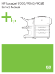
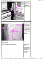
Open the right door and lift up the registration flap. A folded piece of paper can get stuck where the PS2 sensor is; use a flashlight to
look carefully in this area. See Figure 1.
Figure 1: Close up of registration sensor
2.
Remove and inspect the duplexer (if equipped). Leave out for troubleshooting purposes.
3.
Inspect all high capacity output (HCO) device paper paths.
4.
Remove and inspect the fuser; if not damaged, reinstall it.
5.
After doing this, power cycle the printer again. If the message clears and the printer goes to a READY status, then reinstall the
Duplexer (if equipped) and power cycle the printer. If the 13.20 error returns then the issue is with the Duplexer, give it a thorough
inspection and remove any stuck paper and check the sensors in the Duplexer. Test again, if the 13.20 error keeps returning only
with the Duplexer installed, then replace it.
6.
If the printer has just been serviced and the HVPS was replaced: During printer repair if the Fuser High Voltage Cable contacts get
knocked out of place from the fixing connector holder assembly, the printer will immediately start up to a 13.20 error. See the
following section titled “13.20 Errors Immediately after Service Repair For Replacement Of HVPS.” This issue is not likely to be very
common.
7.
If the printer is displaying the CHECKING PAPER PATH message during restart, but still goes to a 13.20 error message, then see
http://h30125.www3.hp.com/hpcsn/km/utils/ViewDocument.aspx?code=TINF:8:%23USA&DocID=emr_... 6/14/2007
HP Channel Services Network
Page 4 of 18
the following section titled “13.20 errors caused by Tray 1, Registration or Face Down Delivery Assemblies.”
8.
If after performing all of the previous troubleshooting, the information in Step 3 does not apply and the printer still boots up to a 13.20
but does not display CHECKING PAPER PATH during start up, then see the following section titled “During Power up Printer Never
Displays CHECKING PAPER PATH on Control Panel.”
top
13.20 errors caused by Tray 1, Registration or Face Down delivery assemblies
If the printer still starts up to a 13.20 error message but does display CHECKING PAPER PATH on the control panel, then there is an issue
with either Tray 1, the registration assembly or the face down delivery assembly (top output). This may be as simple as removing stuck
media from the sensors or may involve replacing one of these assemblies, if damaged. An issue with any of these assemblies can cause a
13.20 error message.
Check the Tray 1 assembly for any stuck paper or damage before replacing any parts. A damaged Tray 1 can cause the printer to boot up
to a 13.20 error and display CHECKING PAPER PATH on the control panel. Remove Tray 1 from the printer and power up the machine, if
the printer boots to a READY status then the issue has been isolated to Tray 1.
Parts required (part numbers are subject to change)
Part description
Part number (part numbers are subject to change)
Registration assembly
RG5-5663-060CN
Face down delivery assembly
RG5-5643-080CN
Tray 1* optional if damaged
C8568-67902* optional if damaged
* denotes optional parts
top
Instructions on replacing the face down delivery assembly
NOTE: After removing the left top cover look at the delivery assembly. Examine the two sensors and their respective flags for any damage
or stuck media. If there is stuck media in the sensors, remove it and verify the flags move freely through the sensors. If this is the case then
the issue is probably resolved at this point. Reassemble the printer and test to verify the error message has been cleared. If the assembly is
damaged then proceed with replacing it.
Figure 2: Control panel removal
1. Open the
front cover.
2. Release the
two tabs on the
underside of the
control panel by
pulling them
toward the front
of the printer.
(Figure 2, callout 1.)
3. Lift the
control panel
straight up.
4. Unplug the
cable connector
on the
underside of the
control panel
and remove the
control panel.
1 - Retaining tabs on underside of control panel
Figure 3: Right-top cover removal
1. Remove the
control panel.
http://h30125.www3.hp.com/hpcsn/km/utils/ViewDocument.aspx?code=TINF:8:%23USA&DocID=emr_... 6/14/2007
HP Channel Services Network
1 - Small plastic cover inside right door
2 - Three silver screws
Figure 4: Left top cover removal
1 - Two silver screws
2 - Opening for control panel cabling to feed through
Page 5 of 18
(Figure 2).
2. If the
multipurpose
Tray 1 is
installed,
remove it.
3. Open the
right door.
4. Remove the
small plastic
cover from the
upper-right side
of the right door
by releasing the
tab on the
inside of the
door. (Figure 3,
call-out 1.)
5. Remove
three silver
screws. (Figure
3, call-out 2.)
6. Lift the righttop cover up
and away from
the printer.
To reinstall:
NOTE: If the
left cover was
removed it
must be
replaced first,
then replace
the right
cover.
1. Remove
the control
panel.
(Figure 2.)
2. Remove
the right top
cover.
(Figure 3.)
3. Remove
two silver
screws.
(Figure 4,
call-out 1.)
4. Lift the
left-top
cover up
and then
pull it
toward the
right side of
the printer
to release
two locating
tabs (found
on the
underside
of the
cover, on
the left
edge).
To
reinstall:
Be sure to
feed the
control
http://h30125.www3.hp.com/hpcsn/km/utils/ViewDocument.aspx?code=TINF:8:%23USA&DocID=emr_... 6/14/2007
HP Channel Services Network
Page 6 of 18
panel cable
back up
through the
hole in the
left-top
cover.
(Figure 4,
call-out 2.)
Insert the
two locating
tabs (found
on the
underside
of the left
cover, on
the left
edge) into
the locating
holes on the
top of the
printer.
Figure 5: Left back cover removal
1. Remove the
formatter
assembly.
2. Remove
three silver
screws from left
back cover (not
shown).
3. Rotate the
left back cover
toward the back
of the printer to
release the
three retaining
tabs on the left
of the cover
(Figure 5, callout 1), and the
two retaining
tabs on the right
side of the
cover (Figure 5,
call-out 2).
1 - Three retaining tabs on the left side of cover
2 - Two tabs on right side of cover
Figure 6: Delivery assembly removal
1. Remove the
control panel.
(Figure 2.)
2. Remove the
right-top cover
(Figure 3), the
left-top cover
(Figure 4), and
the left-back
cover (Figure
5).
3. Open the left
door.
4. Face the top
of the printer.
5. Unplug one
cable connector
(Figure 6, callout 1).
http://h30125.www3.hp.com/hpcsn/km/utils/ViewDocument.aspx?code=TINF:8:%23USA&DocID=emr_... 6/14/2007
HP Channel Services Network
Page 7 of 18
6. Remove four
gold screws
(Figure 6, callout 2) and two
silver screws
(Figure 6, callout 3).
7. Lift the
delivery
assembly out of
the printer.
1 - Cable connector
2 - Four gold screws
3 - Two silver screws
top
Instructions on replacing the registration assembly
Figure 7: Right door removal
1. Remove Tray 1 if
there is one
installed on the
printer.
2. Open the right
door.
3. Pinch and then
push the two tabs
on the end of the
black strap to
release the strap
ends (see Figure
7.1, call-out 1).
Needle nose pliers
may be used if there
is difficulty with this
step.
4. Disconnect four
locator tabs on the
cable cover and
remove the cover
(see Figure 7.1, callout 2).
1 - Black strap
2 - Locator tabs
Figure 8:
5. Unplug two
multiple-wire cable
connectors (see
Figure 7.2, call-out
3).
6. Lift the right door
up and off the two
http://h30125.www3.hp.com/hpcsn/km/utils/ViewDocument.aspx?code=TINF:8:%23USA&DocID=emr_... 6/14/2007
HP Channel Services Network
Page 8 of 18
hinges and remove
it from the printer.
NOTE: NOTE: Do
not remove the
single grounding
cable shown in
Figure 7.2, call-out
4.
Cable connectors
Grounding cable
Figure 9: Back cover removal
1. Remove two silver
screws from the
right-back cover (see
Figure 8, call-out 1).
2. Remove seven
gold screws from the
back cover (see
Figure 8, call-out 2).
3. Remove the back
cover and the rightback cover together
as one part.
4. Remove Trays 2
and 3.
5. Remove the print
cartridge.
1 - Two silver screws
2 - Seven gold screws
Figure 10: Registration jam removal knob removal
1. Open the front
door.
2. Hold the
registration jam
removal knob firmly,
and remove the silver
screw inside the
knob, (Figure 9, callout 1).
3. Pull the knob off
the printer.
http://h30125.www3.hp.com/hpcsn/km/utils/ViewDocument.aspx?code=TINF:8:%23USA&DocID=emr_... 6/14/2007
HP Channel Services Network
Page 9 of 18
1 - Silver screw
Figure 11: Right rail cover removal
1. Remove Tray 2 and
3 (if not already done).
2. Remove two silver
screws from the right
rail cover (see Figure
10, call-out 1).
3. Lift the upper tab to
release it (see Figure
10, call-out 2) and
push the lower tab to
the right to release it
(see Figure 5, call-out
3).
4. Remove the right rail
cover.
5. Repeat these steps
to remove the left rail
cover.
1 - Right rail cover screws
2 - Upper tab
3 - Lower tab
Figure 12: Paper Input Unit (PIU) removal
1. Remove the right
door (see Figure 7).
2. Remove the back
cover (see Figure 8).
3. Remove Trays 2
and 3.
4. Remove four gold
screws, two from each
rail (see Figure 11.1,
call-out 1).
5. Pull the rails out
from the front of the
printer.
http://h30125.www3.hp.com/hpcsn/km/utils/ViewDocument.aspx?code=TINF:8:%23USA&DocID=emr_... 6/14/2007
HP Channel Services Network
Page 10 of 18
1 - Four gold screws
Figure 13:
6. Face the right side
of the printer.
7. If the 2000-sheet
feeder (Tray 4) is
installed, remove the
Paper Path
Connecting Unit
(PPCU) by sliding two
levers toward the
center of the unit (see
Figure 11.2, call-out
2).
Paper Path Connecting Unit (PPCU)
Figure 14:
8. Remove three
screws from the rightlower cover (see
Figure 11.3, call-out
3).
9. Rotate the lower
edge up to release
two tabs (see Figure
11.3, call-out 4).
10. Remove the rightlower cover.
Three screws
Release two tabs
http://h30125.www3.hp.com/hpcsn/km/utils/ViewDocument.aspx?code=TINF:8:%23USA&DocID=emr_... 6/14/2007
HP Channel Services Network
Figure 15:
Page 11 of 18
11. Face the back of
the printer.
12. Remove the J-220
and J-221 cable
connectors from the
DC Controller (see
Figure 11.4, call-out
5).
13. Carefully unwind
the cables from the
cable guides (see
Figure 11.4, call-out
6).
J-220 and J-221 connectors
Cable guides
Figure 16:
14. Face the right side
of the printer.
15. Push the green
registration handle
down slightly and pull
it out to get access to
the PIU (see Figure
11.5, call-out 7).
16. Remove four silver
screws (see Figure
11.5, call-out 8).
17. Grasp the PIU
handle and lift the PIU
out of the printer (see
Figure 11.5, call-out
9).
CAUTION: The PIU is
heavy.
- Registration handle
Four silver screws
PIU handle
Figure 17:
To reinstall:
1. Verify that the
green handle on the
registration assembly
is in an up position
before reinstalling the
PIU (see Figure 11.6,
call-out 1).
NOTE: The new PIU
does not include the
feed/separation rollers
or torque limiters.
These must be
transferred from the
old PIU to the new
one.
2. Reinstall the rightlower cover before the
right rail cover.
http://h30125.www3.hp.com/hpcsn/km/utils/ViewDocument.aspx?code=TINF:8:%23USA&DocID=emr_... 6/14/2007
HP Channel Services Network
Page 12 of 18
1 - Registration handle in UP position
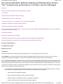
Figure 18: Registration assembly removal
1. Unplug the J-215
cable connector; see
Figure 12.1, call-out 1
from the DC
Controller.
1 - J-215 connector
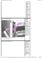
Figure 19:
2. Remove the two
gold screws; see
Figure 12.2, call-out 2
from the registration
assembly.
3. Lift the registration
assembly up slightly,
and then rotate it
downward until it can
be pulled out of the
printer chassis.
CAUTION: Be very
careful not to scrape
the top of the
registration assembly
against the printer
chassis. Small black
plastic pieces on top
of the registration
assembly can easily
be damaged.
http://h30125.www3.hp.com/hpcsn/km/utils/ViewDocument.aspx?code=TINF:8:%23USA&DocID=emr_... 6/14/2007
HP Channel Services Network
Page 13 of 18
Two gold screws
top
How to resolve a False 13.20 error message - During power up printer never displays CHECKING PAPER
PATH on the control panel and the HVPS has notjust been replaced
If the printer still starts up to a 13.20 error and never displays the CHECKING PAPER PATH message see the following note.
NOTE: During boot up, at some point, the printer should display CHECKING PAPER PATH on the control panel. This indicates that the
printer is polling the paper path sensors. It polls the sensors in the fuser first, then the rest of the sensors in the paper path. If the printer
never displays this CHECKING PAPER PATH message during power up and goes straight to a 13.20 error message and the previous
troubleshooting has been performed, then the printer probably has the "false" paper jam scenario and qualifies for the service note repair. A
change has been made in the DC Controller firmware to eliminate the false (the fuser is incorrectly reporting a jam condition when there is
not one) 13.20 paper jams. The fuser should also be replaced at the same time to ensure no extra toner or calcium carbonate that may
have built up in the fuser causes any future issues.
Parts required (part numbers are subject to change)
Part description
Part number (part numbers are subject to change)
Fuser assembly
C8519-69033 110V, C8519-69034 220V
DC Controller
C8519-69028
NOTE:Technicians: Print a Configuration page and check the printer number. This number should be either an 18 or 19. This number
indicated the DC Controller revision. Numbers 18 and higher have the fix described in the Service Note to eliminate the false 13.20 jams.
top
Service Note Information
Service note information (if applicable)
Service note numbers
Printer model
C8519A-04
HP LaserJet 9000
C8520A-04
HP LaserJet 9000n
C8521A-04
HP LaserJet 9000dn
C8522A-04
HP LaserJet 9000hns
Affected serial numbers
Starting serial number
XXXX000000
Ending serial number
XXXH000001
top
http://h30125.www3.hp.com/hpcsn/km/utils/ViewDocument.aspx?code=TINF:8:%23USA&DocID=emr_... 6/14/2007
HP Channel Services Network
Page 14 of 18
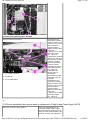
Instructions on replacing the DC Controller
The Formatter needs to be removed first, followed by the back cover then the High Voltage Power Supply (HVPS) to access the DC
Controller.
Figure 20: Back cover removal
1. Turn the printer off
and disconnect the
power cable.
2.Remove two silver
screws (Figure 13, callout 1) from the rightback cover.
3. Remove seven gold
screws (Figure 13, callout 2) from the back
cover.
4. Remove the back
cover and right-back
cover as one part.
1 - Two silver screws
2 - Seven gold screws
Figure 21: Remove connectors
1.Remove the back
cover.
CAUTION: The flat
ribbon cable is fragile.
Do not bend or fold it
:.
2.Remove the flat
ribbon cable connector
(Figure 14, call-out 1)
from the DC controller.
3. Unplug the lowvoltage power supply
cable connector (Figure
14, call-out 2) from the
DC controller, and
unroute the cable from
the cable guides
(Figure 14, call-out 3).
1 - Flat ribbon cable connector
2 - Low-voltage power supply cable
3 - Cable guides
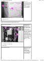
Figure 22: Remove screws
4.Remove three silver
screws (Figure 14.2,
call-out 4).
5.Push the black
locking tab (Figure
14.2, call-out 5) away
from the HVPS, and
remove the HVPS.
http://h30125.www3.hp.com/hpcsn/km/utils/ViewDocument.aspx?code=TINF:8:%23USA&DocID=emr_... 6/14/2007
HP Channel Services Network
Page 15 of 18
Three silver screws
The black locking tab that holds in the HVPS
Figure 23: Remove connectors
1 - 1- 17 Cable connectors
2 - 3- Small tab
3 - 4- Two metal holders
CAUTION: Be very
careful when removing
cable connectors J-215,
J-219 and J-213. Do not
bend or break the
component that is
adjacent to these cable
connectors.
1. Remove the 17 cable
connectors (Figure
15.1, call-out 1).
3. Release the small tab
(Figure 15.2, call-out 3),
and rotate the top edge
of the DC Controller
away from the printer.
4. Remove the DC
Controller from the two
metal holders (Figure
15.2, call-out 4).
5. Reinstall in the
reverse order, be
careful when
reconnecting the cable
connectors to the DC
Controller.
CAUTION: Be very
careful when removing
cable connectors J-215,
J-219 and J-213. Do not
bend or break the
component that is
adjacent to these cable
connectors.
1. Remove the 17 cable
connectors (Figure
15.1, call-out 1).
top
13.20 Errors immediately after service repair for replacement of High Voltage Power Supply (HVPS)
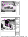
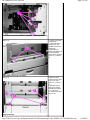
Figure 24: Contacts in wrong position
During removal/replacement, the
Fuser High Voltage Cable contacts
can be knocked out of place from the
fixing connector holder assembly. As a
result, the contacts cannot align with
http://h30125.www3.hp.com/hpcsn/km/utils/ViewDocument.aspx?code=TINF:8:%23USA&DocID=emr_... 6/14/2007
HP Channel Services Network
Page 16 of 18
the contacts on the HVPS. This error
will occur when one or both of the
contacts are out of place (Figure 16,
call-out 1).
1 - Fuser cable contacts are to the right of the housing
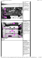
Figure 25: Contacts in correct position
1 - Contacts are over the left edge of the housing
Instructions:
1. Remove the back cover.
2. Remove the High Voltage Power
Supply (HVPS).
3. Push the contacts to the left so they
cover the left edge of the housing
(Figure 17, call-out 1).
4. As shown above (Figure 17, call-out
1) when the leaf spring contacts are
pushed on top of the connector holder
housing, the contacts cannot make
contact with the pressure roller bias
and the paper wrap detection
connections on the HVPS. Once
repositioned, the contacts will now
make contact with the HVPS.
5. If readjusting the leaf spring
contacts does not fix the problem,
send an HVPS and a fuser high
voltage cable.
Possible parts required (part numbers are subject to change)
Part description
Part numbers
High Voltage Power Supply (HVPS)
RG5-5728-100CN
Fuser High Voltage cable*
RG5-8034-000CN *
*Denotes optional parts
NOTE: In most cases, simply repositioning the leaf spring contacts will resolve the issue. Do not replace the HVPS and the fuser high
voltage cable until the leaf spring contacts have been positioned correctly to the left of the housing.
Verify printer functionality
When the leaf spring contacts have been repositioned properly and the printer has been reassembled, print several paper path tests from
the printer control panel.
top
Removal and replacement instructions for 13.20 after service repair for replacement of HVPS
Figure 26: Back cover removal
1. Turn the printer off
and disconnect the
power cable.
2.Remove two silver
screws (Figure 18, callout 1) from the right-
http://h30125.www3.hp.com/hpcsn/km/utils/ViewDocument.aspx?code=TINF:8:%23USA&DocID=emr_... 6/14/2007
HP Channel Services Network
Page 17 of 18
back cover.
3.Remove seven gold
screws (Figure 18, callout 2) from the back
cover.
4. Remove the back
cover and right-back
cover as one part.
1 - Two silver screws
2 - Seven gold screws
Figure 19: High Voltage Power Supply (HVPS) removal
Figure 27: Remove connectors
1.Remove the back
cover (page 122).
WARNING: he flat
ribbon cable is fragile.
Do not bend or fold it.
T
2.Remove the flat
ribbon cable connector
(Figure 19.1, call-out 1)
from the DC Controller.
3. Unplug the lowvoltage power supply
cable connector (Figure
19.1, call-out 2) from
the DC Controller, and
unroute the cable from
the cable guides
(Figure 19.1, call-out
3).
1 - Flat ribbon cable connector
2 - Low-voltage power supply cable
3 - Cable guides
Figure 28: Remove screws
4.Remove three silver
screws (Figure 19.2,
call-out 4).
5. Push the black
locking tab (Figure
19.2, call-out 5) away
from the HVPS, and
remove the HVPS.
http://h30125.www3.hp.com/hpcsn/km/utils/ViewDocument.aspx?code=TINF:8:%23USA&DocID=emr_... 6/14/2007
HP Channel Services Network
Page 18 of 18
4- Three silver screws
5- The black locking tab that holds in the HVPS
top
http://h30125.www3.hp.com/hpcsn/km/utils/ViewDocument.aspx?code=TINF:8:%23USA&DocID=emr_... 6/14/2007
June 2002 Featured Technical Article
Helpful Hints on New HP LaserJets
This article originally appeared in the March 2002 issue of Image Source (Vol. 5, Issue 3).
Working on a new printer, I often find myself saying "I wish I already knew the quirky areas of the
machine rather than stumbling across them Ð but I guess that's just part of the learning curve on
new printers." If you've ever found yourself thinking the same thing, today I have a treat for you.
We have recently gone through a couple of new products and found some "quirks" that will likely
save you several hours of head scratching and under-your-breath mumblings.
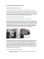
HP LJ 9000 HV Contacts can cause 13.20 Paper Jam
What does the high voltage power supply (HVPS) have to do with paper jams?
Nothing, many would say, but recently after reinstalling an HVPS into an HP LJ 9000 printer, we
started getting instant 13.20 paper jams. What could be going on? After checking for paper that
may have been left in the machine and verifying the flags were ok, I opened the Service Manual
(OK, I was really stumped). One of the steps in the Service Manual is to verify the proper seating
of the leaf springs under the HVPS. After removing the HVPS, I found that one of these leaf
springs was bent to the right (Figure 1) and out of the case. These leaf springs should be to the
left over the case, so when you reinstall the HVPS, the contacts on the board touch the leaf
springs. These contacts are labeled TB1009 & TB1010 on the HVPS (Figure 2).
Figure 1
Figure 2
What do these contacts have to do with a paper jam problem? They monitor pressure roller bias
connections between the fuser and HVPS. These connections are routed through the fuser
connectors and complete the fuser wrapping jam detection circuit. The wrapping jam detection
circuit is an arm on a solenoid that physically contacts the pressure roller when this check is
done. It compares the checked value to the applied value for differences. If they differ, the circuit
determines that a wrapping jam has occurred and stops the printer (a wrapping jam is when
paper wraps itself around the pressure roller). If you get the 13.20 error and really are having
trouble figuring it out, check for paper wrapped around the pressure roller. Then, check these
contacts and leaf springs under the HVPS.
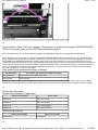
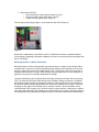
Follow these steps to get to this area of the printer:
1. Remove the rear cover, by removing seven gold screws and two silver screws in wrap
around panel on right side.
2. Remove the HVPS by:
o
o
o
Disconnecting two cables (green arrows, Figure 3).
Removing three screws (red arrows, Figure 3).
Unlatch one tab (yellow arrow, Figure 3).
This will expose the springs (Figure 1) and contacts on the HVPS (Figure 2).
Figure 3
Now that we understand a quirk with the new HP LJ 9000 that can cause a headache without
even knowing it happened (until power is applied), let's move on to the quirk that can happen with
the HP 1200/1220.
Reversing the HP LJ 1200 HV Connectors
Most technicians out there will laugh when they hear the story I am about to tell--though I didn't
until days later. I spent a lot of time troubleshooting this problem, which hopefully you can avoid
simply by reading this article. It all started when an HP LJ 1200 printer came in for repair with a
flashing amber error light. This light, when flashing, indicates a general error such as paper out,
paper jam, door open or incorrectly installed toner cartridge.
I began troubleshooting by checking all the sensor flags, which were all intact and moving freely.
Then, I checked the door open switch and the toner cartridge, finding no problems. I contacted
HP technical support and they suggested that either the motor was the cause of this problem or
the formatter, which could be giving a false error. Both were changed with no effect. I even tried
changing out the engine control board, with no success. However, upon reinstallation, it was
noticed that the HVPS contacts, J301 & J304 could be cross-connected. I referred to the manual
once again and guess what--the contacts were in fact hooked up in reverse, causing the printer to
not recognize the toner cartridge (see Figures 4 and 5 for the correct and incorrect connections).
Figure 4
Figure 5
Upon further investigation, the customer had admitted to trying to fix the printer himself for a
separate problem, and not knowing which wire went to where, he assumed it didn't matter. When
connecting these wires, note that both are red and both connect the exact same way. It's
important not to cross them as they go straight up to their appropriate connectors (again, see
Figures 4 and 5 for the proper and improper connections).
To access this area of the printer:
1. Open the toner cartridge door.
2. Remove the left side panel (as looking from the front).
3. Remove the two screws as indicated by arrows in figure 6 and remove the rear panel.
Figure 6


![2 Cliccate su [OK].](http://vs1.manualzilla.com/store/data/006157023_1-5e7c670791eed41ab79bb8c5559b9f3a-150x150.png)