1
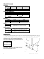
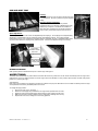
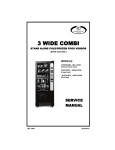
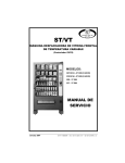
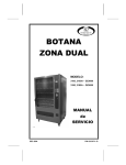
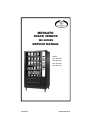
MERCATO SNACK VENDOR WS SERIES SERVICE MANUAL Models: 3537: WS 3000 3538: WS 4000 3535: WS 5000 3536: WS 7000 October 08 P/N 4216320 Rev A TABLE OF CONTENTS INTRODUCTION......................................................................... 2 SPECIFICATIONS ...................................................................... 2 UNPACKING............................................................................... 2 INSTALLATION .......................................................................... 3 GROUNDING & ELECTRICAL.................................................... 3 DOOR STOP BOLT INSTALLATION .......................................... 3 LOADING PRODUCTS ............................................................... 3 AUGER AND TRAY ADJUSTMENT ............................................ 3 TRAY SPACING ............................................................................................ 3 SWITCHING FROM CANDY TO SNACK ..................................................... 4 SWITCHING FROM SNACK TO CANDY ..................................................... 4 GUM AND MINT TRAY ................................................................................................... 5 AUGER TIMING............................................................................................. 5 TRAY CONFIGURATION .............................................................................. 6 TABLE 1: AVAILABLE AUGERS .................................................................. 6 CONTROLLER FUNCTIONS ...................................................... 6 SERVICE MODE .................................................................... 7 SERVICE MODE BUTTON ...................................................................7 KEYPAD ...............................................................................................7 PROGRAMMING INSTRUCTIONS ......................... 8 1 TUBE FILL/ DISPENSE COINS ......................................... 8 2 MOTOR COUNT ................................................................. 8 4 CONFIGURATION .............................................................. 9 5 PRICING ........................................................................... 11 6 ACCOUNTING .................................................................. 11 7 ADVANCED OPTIONS ..................................................... 12 9 TEST ................................................................................. 12 0 DIAGNOSTIC .................................................................... 12 LEAD THROUGH MESSAGES ............................. 13 PREVENTATIVE MAINTENANCE ......................... 13 PARTS ORDERING PROCEDURE ....................... 13 BEFORE CALLING FOR SERVICE ....................... 14 The Model and Serial numbers are needed for you to obtain quick service and parts information for your machine. The numbers are given on the identification plate located on the back side of the cabinet of the machine. MODEL NUMBER: SERIAL NUMBER: ___________________________________ ___________________________________ INTRODUCTION This manual contains instructions, service and installation guidelines for the Mercato WS Series Glass Front Snack product line. The Mercato WS Series models are equipped with an electronic control system. All vending functions, pricing, and features are programmed through the controller. Changes can be made without any additional accessories or remote parts. Selections can be priced individually from $.05 to $999.99 in five cent increments (US currency). When adapted to accept international or foreign currency, the maximum vend price will be 255 times the smallest denomination of coin being accepted. Cash Accountability records Total Cash transactions and Total Vend cycles performed by the vendor. Information for individual selections, complete rows or total machine can be compiled and used for inventory and ordering records. Electrical malfunctions are recorded and displayed when the machine is placed in Service Mode. Non-functioning motors or selections are indicated. Each selection has an individual motor. Functional selections will continue to operate if other motors become non-functional. The vending sequence is ―first-in, first-out‖ for each selection, eliminating the need for stock rotation to assure product freshness. Options: The iVend™ Optical Sensing option assures that the customer receives the purchased product or receives a refund. Read this manual thoroughly. Become familiar with the machine’s components and features. The initial setup of a vending machine is a very important step toward insuring that the equipment operates trouble-free. Carefully follow the instructions for the initial installation of the machine to avoid service problems and minimize setup time. Access to the service area of this machine should be permitted only to individuals having knowledge and practical experience in machine setup and loading, especially in the areas of safety and hygiene. WS SERIES • 4216320 Rev A If you have questions concerning the information in the manual, replace-ment parts, or the operation of the vendor, note your machine’s Model # and SN # before contacting your local distributor or: VendNet 165 North 10th Street Waukee, IA 50263 Phone: (800) 833-4411 Parts Fax: (515) 271-8555 Sales Fax: (515) 271-8555 E-mail: [email protected] www.VendNetUSA.com SPECIFICATIONS DIMENSIONS Model Type Width Weight Depth Height 3537 3-Wide 29.3 inches 445 lbs. 3538 4-Wide 35.2 inches 519 lbs. 34.75 inches 72 inches 3535 5-Wide 41.1 inches 626 lbs. FACTORY TRAY CONFIGURATION Type Trays Selections 3-Wide 6 24 (expandable to 36) Gum & Mint (optional) 4-Wide 6 36 (expandable to 48) 5-Wide 6 40 (expandable to 60) 4 selections ELECTRICAL Voltage Cycle Amperage Transformer 115 VAC 60 Hz 1.2 115 VAC – 24 VAC 230 VAC 50 Hz 0.6 25 VAC COINAGE MDB Version International Domestic Any MDB validator, coin mechanism or card reader VENDOR OPERATION Location Sound Level Recommended Operating Temperature Suitable for indoor use only. This appliance is not suitable for installation in an area where a water jet could be used. Produces less than 70 dBA during normal operation. Between 32° and 100° F° (0° and 37.8° Celsius. UNPACKING This machine was thoroughly inspected before leaving the factory and the delivering carrier has accepted responsibility for this vendor. Note any damage or irregularities at the time of delivery and report them to the carrier. Request a written inspection report from the claims inspector to file any claim for damage. File the claim with the carrier (not the manufacturer) within 15 days after receipt of the machine. Carefully remove the outside packing material being careful not to damage the machine’s finish or exterior. Inspect the machine for concealed shipping damage. Report any damage hidden by the shipping material directly to the delivering carrier on a Hidden Damage Report. NOTE: if the power supply cord is damaged, it must be replaced by the manufacturer, its service agent, or similarly qualified individual in order to avoid hazard. Remove the knock-away support by placing a 2X6 under the vendor. Insert a large screwdriver or prying tool into the groove and split it in two. Turn the leveling screws as far as possible. See Figure 1. Figure 1 2 MERC AT O WS SERIES • 4216320 R ev A INSTALLATION Position the vendor in its place of operation on a flat, smooth surface in such a way that the vendor’s power cord easily reaches the power outlet or receptacle (DO NOT USE AN EXTENSION CORD), and check that the door will open fully without interference. Leave at least six inches of space between the back of the machine and any wall or obstruction for proper air circulation. Level the vendor, making sure all levelers are touching the floor. The vendor must be level for proper operation and coin acceptance through the coin mechanism. Retrieve the vendor keys from the coin return cup. Open outer door and remove all internal packing material. Consult local, state, and federal codes and regulations before installing the vendor. GROUNDING (EARTHING) & ELECTRICAL Refer to the Safety Manual and Installation Guidelines manual (P/N 4206816) found in the service package shipped with your machine. Before connecting the vendor, the integrity of the main electrical supply must be checked for correct polarity, presence of ground (earth) and correct voltage. These checks should be repeated at six-month intervals with the routine safety electrical testing of the vendor itself. If the receptacle is not properly grounded or polarized, contact a licensed electrician to correctly polarize and/or ground the receptacle to ensure safe operation. A noise suppressor has been installed in this machine to compensate for any mains signal noise that could interfere with the normal operation of the controller. For proper operation of any equipment utilizing electronically controlled components, the equipment should be placed on an isolated, or dedicated, noise-free circuit properly polarized and grounded. Refer to Electrical Specifications in this manual to determine circuit amperage and protection. DOOR STOP BOLT INSTALLATION Replace the top hinge screw with the Door Stop retaining bolt provided in the service package if the door stop function is required. Your machine has a top hinge screw installed at the factory. The Door Stop Bolt (included in the packaging) may be installed in place of the screw as shown. The bolt provides a door stop to prevent the machine door from opening fully into obstacles or machines to the right of the machine. The service package included with your machine includes a Door Stop Bolt for use in cases where a door stop is required. LOADING PRODUCTS To load products, lift the tray slightly and pull forward until the tray stops. The uppermost trays tilt for easier loading. Load product from front to back making sure all items fit freely between the augers. Do not attempt to force oversize items or packages into the spaces. Do not skip a space. Place the product on the bottom of the compartment on the product augers with the labels facing the front of the machine for easy identification by the customer. See Figure 2. To vend properly the item being vended must be wider and taller than the diameter of the auger being used. Undersize items could cause vend problems. If the product does not fit the auger properly, use a different pitched auger. See Tables 1 and 1b for augers available from your distributor or service entity. AUGER AND TRAY ADJUSTMENT By retiming the augers and/or adding product pushers, difficult-to-vend items can be dispensed more dependably. By altering tray spacing, larger items can be vended. By changing the tray configuration, different product mixes can be accommodated. TRAY SPACING Trays can be adjusted up or down in one-inch increments to provide additional headroom for vending taller products. When increasing the height in one area, the same amount of space will be lost by the tray above or below. 3 WIDE AND 4 WIDE TRAY SPACING ADJUSTMENTS Figure 2 Pull out the tray to be adjusted until it stops. Disconnect the tray harness from its snap-open harness clamp on the right sidewall. See Figure 3. Disconnect the tray plug from its receptacle on the right sidewall. Lift up on the front of the tray and pull slightly forward approximately ½ inch (1.5 cm) to clear tray stop. Lift up on the rear of the tray and remove it from the vendor. Disengage both left and right tray rails from their corresponding slots on the left and right sidewalls by pulling inward on the bottom front of each rail and lifting its flange out of the slot. 7. Pull each rail forward to disengage its rear tabs from the hole in the rear wall. 8. Relocate both left and right rails by reversing steps 6 and 7. 9. Replace the tray by placing its rear rollers on the left and right rails and lift up on the front of the tray as it is pressed back. 10. Install the tray plug into its receptacle on the right sidewall. 11. Reengage the tray harness into its harness clamp and snap closed. 12. Test vend the tray in its new position to assure that the tray plug is properly seated. 1. 2. 3. 4. 5. 6. MERC AT O WS SERIES • 4216320 R ev A 3 5 WIDE TRAY SPACING ADJUSTMENTS 1. 2. 3. 4. 5. 6. 7. 8. 9. 10. 11. 12. 13. 14. Pull out the tray to be adjusted until it stops. Disconnect the tray harness from its snap-open harness clamp on the right sidewall. See Figure 3. Disconnect the tray plug from its receptacle on the right sidewall. Lift up on the front of the tray and pull slightly forward approximately ½ inch (1.5 cm) to clear tray stop. Lift up on the rear of the tray and remove it from the vendor. Locate the release levers on the left and right tray rails. (see figure 4) Swing the release levers all the way up to unlatch. Lift up on the rear of the tray and remove it from the vendor. Relocate both left and right rails. a. Remove tray mounting screws b. Pull each rail forward to disengage its rear tab from the hole in the rear wall. (see figure 5) Relocate both left and right rails by reversing step 8. Assure that rails are level from Figure 4: Tray rails front to back and right to left. Replace the tray by placing its rear rollers on the left and right rails and lift up on the front of the tray as it is pressed back, taking care to keep the tray level as it is pushed in. Swing the tray release levers all the way down. Install the tray plug into its receptacle on the right sidewall. Reengage the tray harness into its harness clamp and snap closed. Test vend the tray in its new position to assure that the tray plug is properly seated. SWITCHING FROM CANDY TO SNACK NOTE: THIS OPTION REQUIRES THE PURCHASE OF A CONVERSION KIT CONVERSION STEPS: 1. 2. 3. 4. 5. 6. 7. 8. 9. Unplug and remove the tray assembly from the vendor. Place the tray harness in the tray before removal. Remove the motor cover by pulling up on the front edge of the cover to clear the stop and then pull forward on the cover. Remove the existing tray divider and discard. Remove the existing auger assembly and discard. Remove the existing ―even‖ numbered motor. This motor will not be needed. Tape or secure the terminals removed from the motor and place aside. Move the ―odd‖ numbered motor to the center slot of the compartment. Install the auger retainer furnished in the conversion kit. Install the auger assembly furnished in the conversion kit, making sure that the motor coupling properly engages the motor and is securely snapped over the vertical rail or retaining ring on the tray. 10. Re-assemble the motor cover removed in step 2. 11. Replace the tray assembly into the vendor, making sure that the tray is properly located and latched; connect the tray harness. 12. Set the selection vend price and adjust the price scroll to reflect same. Large item selections will be ―odd‖ numbers. For example, selections 23 and 24 are converted to a single selection, 23. 13. Test vend the converted selection for proper operation and price setting. SWITCHING FROM SNACK TO CANDY NOTE: THIS OPTION REQUIRES THE PURCHASE OF A CONVERSION KIT CONVERSION STEPS: 1. 2. 3. 4. 5. 6. 7. 8. 9. 10. 11. 12. 13. 4 Unplug and remove the tray assembly from the vendor. Place the tray harness in the tray before removal. Remove the motor cover by pulling up on the front edge of the cover to clear the stop and then pull forward on the cover. Remove the existing auger assembly and discard. Remove the auger retainer and discard. Move the motor from the center slot to the left slot in the compartment. Add the new motor (furnished in the conversion kit) in the right hand slot of the compartment. Properly wire the motor and switch. Refer to the Schematic diagram for proper wire colors and location. Install the divider furnished in the conversion kit. Install the auger assemblies furnished in the conversion kit, making sure that the motor couplings properly engage the motors and are securely snapped over the vertical rail or retaining ring on the tray. Re-assemble the motor cover removed in step 2. Replace the tray assembly into the vendor, making sure that the tray is properly located and latched; connect the tray harness. Set the selection vend price and adjust the price scroll to reflect same. Test vend the converted selections for proper operation and price settings. MERC AT O WS SERIES • 4216320 R ev A GUM AND MINT TRAY Loading: Load G&M spirals from front to back as shown being sure to not skip spaces. Be sure to push the tray back fully after loading. Selection Divider Installation: Divider Screw s For products that are narrower than the provided compartment size (i.e. 5 stick gum or Breathsavers mints) dividers may be required. The dividers are installed on either side of the compartment to center the products for proper vending. Each divider requires three screws for installation as shown. Spiral Adjustment: The G&M spirals are held to the motors with adjustable splined couplings. The couplings can be adjusted every 20 degrees. This adjustment may be required to properly vend different products. The coupling is pulled forward and out of the motor, spiral timing is adjusted, and then reinstalled. Be sure to reinstall the black rubber cap on the back shaft of the coupling to fully retain the spiral. Test vend and adjust the timing as necessary. Pull coupling forward to remove from motor Reinstall black rubber cap to coupling shaft PRODUCT PUSHERS Order product pushers P/N 4025748. Snaps on to end of auger. See Figure 3. AUGER TIMING. The shape, size and thickness of product affects how well it falls off the tray. Most items can be vended successfully when the auger end is positioned at 6 o’clock. If vending problems occur with auger ends at the standard 6 o’clock position, adjust the drop-off either with product pushers or by retiming the auger. Auger Retiming Each auger can be rotated in 20º (degree) increments for a different drop-off point. Most items can be vended successfully when the auger end is positioned at the factory set default position of 6 o’clock. To change the auger position: 1. 2. 3. 4. 5. Remove the motor cover. (see figure ) Raise the motor slightly and pull forward on the auger until it separates from the motor. Rotate the auger to the desired position and reinsert the auger coupling into the motor. Make sure the auger coupling is seated over the vertical rail or retaining rib on the tray. Replace the motor cover, making sure it is securely tightened. MERC AT O WS SERIES • 4216320 R ev A 5 TRAY CONFIGURATION SNACK/CANDY/FOOD TRAY Each auger can be rotated in 20° (degree) increments for a different product vend drop-off point. Most items can be vended successfully when the auger end is positioned at 6 o'clock. The general rule is - the narrower the product, then the higher the timing. Thick Products - 4-6 o’clock Most products – 6 o’clock Thin Products - 6-8 o’clock TO CHANGE AUGER TIMING 1. Remove the motor cover. See Figure 6f. 2. Raise the motor slightly and pull forward on the auger until it separates from the motor. 3. Rotate the auger to the desired position and re-insert the hub (auger coupling) into the motor. The hub (auger coupling) must be seated over the vertical rail or retaining rib on the tray. 4. Replace the motor cover making sure it is securely tightened. 5. Test vend to make sure product vends correctly. Figure 6f. Motor & Auger (Standard Tray) TABLE 1: AVAILABLE AUGERS MERCATO WS Series TYPE CANDY SNACK PRODUCT WIDTH THICK 3.25 3.16 2.37 2.10 1.89 1.72 2.75 1.55 1.22 1.00 0.71 0.51 3.25 3.16 2.71 2.37 1.89 5.50 1.55 1.22 1.00 0.51 QTY 5 6 8 9 10 11 12 15 18 24 30 5 6 7 8 10 12 15 18 STANDARD PART NUMBER 4200272.145309 4200272.106309 4200272.142309 4200272.105309 4200272.131309 4200272.132309 4200272.104309 4200272.100309 4200272.101309 4200272.102309 4200272.103309 4200272.139309 4200272.138309 4200272.110309 4200272.111309 4200272.107309 4200272.108309 4200272.109309 4200272.134309 30 4200272.133309 DUAL AUGER PART NUMBER 4205532.145309 4205532.106309 4205532.142309 4205532.105309 4205532.131309 4205532.132309 4205532.104309 4205532.100309 4205532.101309 4205532.102309 4205532.103309 CONTROLLER FUNCTIONS This vending machine is equipped with a GVC2 controller. Sales Mode The machine automatically defaults to Sales Mode after it is turned on. The vendor accepts deposits, pays out change and dispenses product to the customer. Display Credit If a selection is made and credit has not been established, the price for that selection is displayed briefly. When money or credit is accepted, then the amount of credit is displayed. If the coin levels in the coin mechanism payout tubes are below the low-level sensors, the indicator light ―USE EXACT CHANGE‖ will light up. Make Selection If a selection is made and the accumulated credit is greater than, or equal to, the price of the selection, then a vend attempt will take place. If credit is less than the selection price, the price is displayed and will flash. 6 MERC AT O WS SERIES • 4216320 R ev A Vend Cycle 1. 2. 3. 4. The normal home-switch-vend cycle will be used. Both the vend motor and a vend timer are started. The selection motor rotates to the home-switch position. If there is a home-switch signal, then the vend is considered successful. If there is no home-switch signal, and the vend timer has expired, then the vend failed. The vend motor is shut down and ―MAKE ANOTHER SELECTION‖ indicator light is turned on. The customer can press selection buttons to make another selection or they can press the coin return button. Credit and Counters After a successful vend, the amount of remaining credit is displayed until all coinage is paid back. The total non-resettable vend count is incremented by one and the total non-resettable cash value is incremented by the price of the vended selection. The counter rollovers occur at 999,999 and $999,9999.99 respectively. The resettable vend count is incremented by one. The resettable total cash value is incremented by the price of the vended selection. If never reset, the counter rollovers occur at 999,999 and $999,999.99 respectively. Test vends are not included in the counter totals. SERVICE MODE The Service Mode is used to access the programming features of the controller: Set Price, Test Vend, Retrieve Accounting Information, or Set Custom Program Settings. If credit exists when entering the Service Mode, it will be restored when the machine is returned to Sales Mode. SERVICE MODE BUTTON The Service Mode Button is located near the top right corner of the controller board cover. Press the button to access the Service Mode programming features. Press the button again to exit and return to Sales Mode. If no key is pressed within 60 seconds while in Service Mode, the controller automatically exits to the Sales Mode. KEYPAD Use the buttons on the keypad as directed in the step-by-step instructions in this manual in programming the vendor. DISPLAY Check the display after pressing the Service Mode Button and/or Keypad Buttons to make sure that the program is responding correctly. Buttons 0-9 are used to move between the various modes, menus and sub-menus; while the button is used to enter a menu, confirm or save a setting. See Figure 3 FIGURE 3: KEYPAD PROGRAMMING Refer to the basic programming steps in this manual or on the control cover label. Press the Service Mode Button; check the display for instructions or choices while using the keypad. MERC AT O WS SERIES • 4216320 R ev A 7 SERVICE MODE PROGRAMMING INSTRUCTIONS 1 TUBE FILL/ DISPENSE COINS TUBE FILL Tube Fill counts coins as they are deposited and Shows the dollar amount. STEP DISPLAY 1. Press Service Mode Button 2. Press and begin depositing coins Press 2 times to exit 3. Motor Count 60 At least 15 of each denomination (Sales Mode) TUBE DISPENSE Tube Dispense Pays out coins from the coin mech coin tubes. This mode will also display the current quantity of coins in the coin mech tubes. 1. Press to dispense dollar coin $1.00/coins 2. Press to dispense quarters 0.25/coins 3. Press to dispense dimes 0.10/coins 4. Press to dispense nickels 0.05/coins 5. Press 2 times to exit (Sales Mode) **Note: For dispensing more than a 4 denomination coin mech. use keys greater in the same sequence as shown above.** 2 MOTOR COUNT Displays the total count of working motors. STEP DISPLAY 1. Press Service Mode Button Motors ( - - ) 2. Press then wait. Motors ( - - ) Press to exit. 3. (Sales Mode) 3 OPTIONS This menu allows access to the following features: 3.1 FORCE VEND See GVC2 Programming Manual (P/N 4215507) for more information. 3.2 BILL ESCROW See GVC2 Programming Manual (P/N 4215507) for more information 3.3 MULTI VEND See GVC2 Programming Manual (P/N 4215507) for more information 3.4 FREE VEND See GVC2 Programming Manual (P/N 4215507) for more information 3.5 FAST CHANGE See GVC2 Programming Manual (P/N 4215507) for more information 3.6 OPTICAL VEND Selections that are designated as Optical will have an associated vend operation that differs from the normal vend operation. For 5 milliseconds at the start of a vend, the iVend™ optical sensor will be checked for blockage. If not blocked - the iVend™ Sensor System is used. See GVC2 Programming Manual (P/N 4215507) for more information 8 MERC AT O WS SERIES • 4216320 R ev A 3.7 POINT OF SALE MESSAGE (POS) STEP Turn OFF (or ON) the default scrolling display message. 1. Press Service Mode Button 2. Press NOTE: This does not affect the programmed POS message 3. Press Options POS Message ON 4. Press to toggle ON or OFF. 5. Press to save setting. Press 3 times to exit. 6. DISPLAY Motors ( - - ) POS Message OFF POS Message OFF (Sales Mode) 3.8 SETPOINT (NOT APPLICABLE) 3.9 KEYPAD BACKLIGHT STEP This menu controls the brightness level of the keypad backlight. (Default is 3) DISPLAY 1. Press Service Mode Button 2. Press 3. Press 4. Press repeatedly to change setting. Note:0=Off, 1=Low, 2=Med, 3 =High, 4=Max KB Backlight 3 5. Press to save KB Backlight 3 Press 3 times to exit. 6. Motors ( - - ) Options to view setting. KB Backlight (Sales Mode) 3.0 DROP SENSOR SENSITIVITY (NOT APPLICABLE) 4 CONFIGURATION 4.1, 4.2, 4.3: Configure machine to Snack, Can, or bottle NOT APPLICABLE 4.4 LANGUAGE See GVC2 Programming Manual (P/N 4215507) for more information. 4.5 AUTO_REINSTATE See GVC2 Programming Manual (P/N 4215507) for more information. 4.6 SPACE TO SALES (STS) See GVC2 Programming Manual (P/N 4215507) for more information. 4.7 CUSTOM STS 4.8 TIME/DATE Sets the time and date for timed operations. The following submenus are available: Date Time Daylight Savings MERC AT O WS SERIES • 4216320 R ev A 9 4.8.1 DATE STEP DISPLAY 1. Press Service Mode Button Motors ( - - ) 2. Press Configuration 3. Press Time/ Date menu 4. Press MM/DD/YYYY 5. Press to edit date 06/01/2007 6. Press to save. 06/01/2007 Press 4 times to exit 7. Sales Mode 4.8.2 TIME TIME SETTING Time Setting - This menu controls and displays the current time of day. The display will show a 24 hour format. Examples: 8:05 a.m. = TIME O8.O5 01:15 p.m. = TIME 13.15 11:45 p.m. = TIME 23.45 . STEP DISPLAY 1. Press Service Mode Button Motors ( - - ) 2. Press Configuration 3. Press Date/ Time 4. Press 5. Press to edit 09:00:25 6. Press to save 09:00:25 Press 4 times to exit 7. 08:00:25 for Time menu Sales Mode DAYLIGHT SAVINGS Daylight Savings Setting - This menu controls and displays the currently active daylight savings rule STEP DISPLAY 1. Press Service Mode Button Motors ( - - ) 2. Press Configuration 3. Press Date/ Time 4. Press for Daylight Savings menu DST N AMERICA OFF AUSTRALIA EUROPE 5. Press to toggle between settings 6. Press to save Press 4 times to exit 7. DST N. AMERICA Sales Mode 4.9 HEALTH SAFETY (NOT APPLICABLE) 4.0 ADVANCED CONFIGURATION The following menus are available under this option: Beep Enable Optics Disables Motor Type Talker Password Set Defaults Temperature (not applicable) See GVC2 Programming Manual (P/N 4215507) for more information. 10 MERC AT O WS SERIES • 4216320 R ev A 5 PRICING Price Setting - This menu allows three (3) methods for assigning prices: ITEM — by individual selections ROW— by shelf or tray ALL ITEMS — by entire machine. COUPONS — by Item, Row, or ALL TOKENS — by Item, Row, or ALL COMBO The maximum price that can be set is $655.35. 5.1 ALL This menu allows you to set the selection price of every item all at once. Time Saving Tip: Instead of setting the price of each item one at a time, it is much faster to set the common price of the entire machine; then go back and set the price of each item or row. STEP DISPLAY 1. Press Service Mode Button 2. Press 3. Press to enter price ALL Items $0.50 4. Press to save. ALL Items $0.50 Press 3 times to exit. 5. Motors ( - - ) Pricing (Sales Mode) 5.2 ROW STEP Use this menu to set the price of a row (shelf) all at the same time. Time Saving Suggestion: Instead of setting the price of one item at a time, set the common price of a Row, then go back and set the price of each item. DISPLAY 1. Press Service Mode Button 2. Press 3. Press Enter row number and price Example: Top row=01, row below top row=02, etc. Program will automatically go to the next Row. Row: - - $0.00 Press to save. Row 01 $0.50 Press 3 times to exit 4. 5. 6. Motors ( - - ) Pricing Row:01 $0.50 (Sales Mode) 5.3 ITEM This menu allows price setting by each selection item. STEP 1. Press Service Mode Button DISPLAY Motors ( - - ) 2. Press Pricing 3. Press Item 4. Enter Item and price Item 010 $0.50 to save. The program will automatically go to 5. Press the next selection number. Item 010 $0.50 6. (Sales Mode) Press 3 times to exit. 5.4 COUPON OR TOKEN Allows the operator to designate the values of coupons or tokens that are accepted by pre-programmed validators. There are 5 programmable settings. See GVC2 Programming Manual (P/N 4215507) for more information. 5.7 COMBO PURCHASES See GVC2 Programming Manual (P/N 4215507) for more information. 6 ACCOUNTING Use this menu to gain access to menus that display or reset data for various types of cash and vend totals. Counts can be viewed by individual items, rows or as the whole machine. See GVC2 Programming Manual (P/N 4215507) for more information. MERC AT O WS SERIES • 4216320 R ev A 11 7 ADVANCED OPTIONS Entering this menu requires entry of a password. The following options are available: Discount Max Change Promo Vend Programmable POS Free Vend Rate Shutdown Exact Change Energy Savings Unconditional Acceptance 8 ENERGY SAVINGS (NOT APPLICABLE) 9 TEST Use this menu to test vend individual motors. The selection will display with the test vend. If a test vend attempt on a particular motor fails, controller will beep. STEP DISPLAY 1. Press Service Mode Button 2. Press Press selection number on keypad and wait Repeat step 3 for other selections. 3. 4. 5. Press Motors ( - - ) Item - - Item 010 (Sales Mode) 3 times to exit. TEST ALL MOTORS This menu will test vend all motors. The selection will display with the test vend. If a test vend attempt on a particular motor fails, then the controller will beep. Satellite machines will also be included in the test. STEP NOTE: 1. Press Service Mode Button Pressing at any time will stop the test. 2. Press and wait. The motor selection number will display while it is being tested. 3. Press 3 times to exit. DISPLAY Motors ( - - ) Item Item 010 (Sales Mode) 0 DIAGNOSTIC STEP This menu is used to perform a self-diagnostics check and display results. 1. Press Service Mode Button 2. 3. DISPLAY Motors ( - - ) Press Diagnostic... Press to start test Checksum Temp Sensor Optical Coin Acceptor Bill Validator Card Reader1 Card Reader2 Tests Completed Press 3 times to exit. (Sales Mode) 0.2 TEST RELAY See GVC2 Programming Manual (P/N 4215507) for more information. 0.3 LOG See GVC2 Programming Manual (P/N 4215507) for more information. 0.4 COIN REJECT RATE See GVC2 Programming Manual (P/N 4215507) for more information. 0.5 BILL REJECT RATE See GVC2 Programming Manual (P/N 4215507) for more information. 12 MERC AT O WS SERIES • 4216320 R ev A 0.6 IVEND ALIGNED STEP DISPLAY 1. Press Service Mode Button Motors ( - - ) 2. Press Diagnostics 3. Press to check I-vend alignment IVend aligned NO/OK CUSTOMER LEAD THROUGH MESSAGES The following messages will be affected by the language selection and are stored in the controller memory. MESSAGE 1 English PLEASE USE EXACT CHANGE MESSAGE 2 English PLEASE INSERT MORE MONEY MESSAGE 3 English PLEASE MAKE ANOTHER SELECTION MESSAGE 4 English OUT OF SERVICE MESSAGE 5 English VENDING OPERATION TO RESUME AT hh.mm MESSAGE 6: English DOOR OPEN ERROR MESSAGE 7 English THANK YOU MESSAGE 8 English FREE ON US For other languages, See GVC2 Programming Manual (P/N 4215507). PREVENTATIVE MAINTENANCE CAUTION: ALWAYS DISCONNECT POWER SOURCE BEFORE CLEANING OR SERVICING WARNING: THIS VENDING MACHINE MUST NOT BE CLEANED WITH A WATER JET. ONCE A MONTH CLEAN CABINET INTERIOR Wash with a mild detergent and water, rinse and dry thoroughly. Odors may be eliminated by including baking soda or ammonia in the cleaning solution. Plastic parts may be cleaned with a quality plastic cleaner. The vend mechanism must be kept clean. Any build-up can cause the mechanisms to malfunction. Do not get the cleaning solution on electrical components. To insure proper vending keep delivery slide area free of dirt and sticky substances. CLEAN CABINET EXTERIOR Wash with a mild detergent and water, rinse and dry thoroughly. Clean occasionally with a quality car wax or cleaner. PARTS ORDERING PROCEDURE When ordering parts, include the following: Model and serial number of the machine Shipping address Address where the invoice should be sent Quantity of parts ordered Any special shipping instructions Desired carrier: air or air special, truck, parcel post, or rail. Signature and ordering date. If a purchase order is used, be sure is it visible and legible Please be sure that you refer to the correct part number, machine model number, and machine serial number when ordering. These can be confirmed by checking the parts manual. NOTE: ―Left‖ or ―Right‖ when used in the name or description of the part are determined while facing the front of the vending machine with the door closed. Mail order to: VendNet™ 165 North 10th Street Waukee, IA 50263 USA MERC AT O WS SERIES • 4216320 R ev A 13 You may also order via E-mail to [email protected]; online at www.vendnetusa.com; phone at 1-800-833-4411; or fax at 1515-271-8555. All orders are carefully packed and inspected prior to shipment. Damage incurred during shipment should be reported at once and a claim filed with the terminating carrier. If you do not have the correct parts manual, contact VendNet™ Answers to other questions may be found at www.vendnetusa.com or call VendNet™ at 1(800)833-4411. Ask for the Parts Department. We will be happy to assist you. You may also e-mail VendNet™ at [email protected]. BEFORE CALLING FOR SERVICE Please check the following: Does your machine have at least 6 inches (15.2 cm) of clear air space behind it? If the power is turned on at the fuse box, is the machine the only thing that does not work? Is the machine plugged directly into the outlet? WARNING: Do not use extension cords! Is the circuit breaker at the fuse box reset? NOTE: Please have your Model and Serial Number handy when you call. NOTES: The contents of this publication are presented for informational purposes only, and while every effort has been made to ensure their accuracy, they are not to be construed as warranties or guarantees, express or implied, regarding the products or services described herein or their use or applicability. We reserve the right to modify or improve the designs or specifications of such products at any time without notice. VendNet™ 165 North 10th Street Waukee, Iowa 50263 United States of America USA & Canada Service (800) 833-4411 Parts (888) 259-9965 Email Web Site International (515) 274-3641 [email protected] www.vendnetusa.com 4213674A.DOC 14 MERC AT O WS SERIES • 4216320 R ev A