1
1657 RLC Digibridge®
Instruction Manual
Foun 1657-0120-07/B1
®QuadTech, Inc., 1992
5 Clock Tower Place, 210 East
Maynard, Massachusetts, U.S.A. 01754
January, 1997
Tel. 978-461-2100
800-253-1230 (Sales)
800-253-1230 (Service)
Fax. 978-461-4295
The material in this manual is for informational purposes only and is subject to change, without notice.
QuadTech assumes no responsibility for any error or for consequential damages that may result from the
misinterpretation of any procedures in this publication.
Contents
Instruction Manual Changes
Specifications
Warranty
Introduction -Section 1
Installation -Section 2
Operation -Section 3
Theory -Section 4
Service and Maintenance -Section 5
Parts Lists and Diagrams -Section 6
~ Product will be marked with this symbol (ISO#3684) when it is necessary for the user to refer
to the instruction manual in order to prevent injury or equipment damage.
These two supplementary pages contain information of improvements or modifications not
documented in the current manual. All references to GenRad in the manual now apply to
QuadTech, Inc.
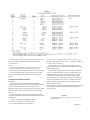
Page -Specifications (Power & Mechanical)
Power should be 90 -250V AC, 50 -60 Hz. Voltage switching is automatic and no
longer selected by rear panel switch. 60 Watts maximum.
Weight should be 10 lbs. (4.5 kg) net, 15 lbs. (6.8 kg) shipping.
Environment reads, Altitude < 2000m, Installation Category 1, Pollution Degree 1
Page - Table of Contents (Parts List and Diagrams -Section 6)
Power supply board (1657-4720) layout and diagram (page 6-13) replaced by Power
supply assembly part number 700011 (no diagrams, repair by module exchange)
Page 1-4 -Figure 1-2, Rear Panel Controls and Connectors
Rear view should show new power supply assembly (PN 700011) without line-voltage
switch.
Page 1-4 -Table 1-2, Rear Panel Connectors and Controls
Ref No. 2R -& Fuse is 6/10A, 250V, 3AG Type, Slow Blow. Replace only with
the same type and rating. To replace, remove fuse drawer by pressing up on release tab.
Ref No. 3R -Line-voltage switch has been deleted, power input is from 90 -250V AC
Page 1-4 -Table 1-3, Accessories
A quantity of two spare fuses are supplied, 6/10A, 250V, 3AG Type, Slow Blow
(QuadTech part number 5330-1100)
Page 2-1 -Safety Inspection
Before operating the instrument inspect the power inlet module on the rear of the unit to
ensure that the properly rated fuse is in place, otherwise damage to unit is possible. Fuse is
6/l0A, 250V, 3AG Type, Slow Blow.
The 1657 is shipped with a standard U.S. power cord, QuadTech PN 4200-0300 (with Belden
SPH-386 socket or equivalent, and 3 wire plug confonning to IEC 320) or an approved
international cord set. Make sure the instrument is only used with these or other approved
international cord sets, which ensures the instrument is provided with connection to protective
earth ground.
In all installations the instrument should be positioned with consideration for ample air flow to the
side and rear panel ventilation holes. An open space around the instrument of at least 3 inches
(75mm) is recommend. The surrounding environment should be free from excessive dust to
prevent contatnination of electronic circuits.
Page 2-1 -Power-Line Connection
Power line switch for 115V or 230V operation has been removed, switching is
automatic for voltages between 90 -250V AC.
Page 2-2 -Figure 2-2
Figure 2-2 does not apply. Only certified line cords which comply with IEC 227 or
IEC 245 should be used.
Page 3-2 -Paragraph 3.1 Basic Procedure, step a
Power line switch for 115V or 230V operation has been removed, switching is
automatic.
Page 5-1 -Paragraph 5.2, Instrument Return
Contacts for QuadTech are:
Sales
800-253-1230
Service
800-253-1230
Technical Assistance
978-461-2100
Page 5-2 & Page 5-3 -Caution Note
Power line switch for 115V or 230V operation has been removed, switching is
automatic.
Page 5-7 -& Paragraph 5.6.1 & Figure 5-3, Disassembly
Power Supply Assembly shown has been replaced by Power Supply Assembly PN
700011.
Page 5-10 -Instrument Cleaning Instructions
Monthly (more or less depending on usage) the built-in test fixture should be cleaned
with a soft brush and isopropyl alcohol. Avoid getting excess alcohol on instrument paint
surfaces, otherwise damage to the finish can result. For additional instrument cleaning
instructions refer to paragraph 5.7.1 (Care of the Test Fixture) and paragraph 5.7,2 (Care of the
Display Panel).
Power Supply Assembly shown in Figure 5-8 has been replaced by Power Supply
Assembly PN 700011.
Page 5-12 - Paragraph 5.8.2, Power Supply
Trouble Analysis procedure does not apply to new Power Supply Assembly P/N 700011.
Page 6-2 - Figure 6-2, Rear View
Rear view should show new power supply (PN 700011) without line-voltage switch
Page 6-3 - Mechanical Parts List, Rear
Items 1 - 4 (power connector, fuse extractor post, line voltage switch & cover) deleted on new assembly
Page 6-12 & Page 6-13 - Parts and Diagrams
Power Supply Board and Parts List shown, PN 1657-4720 has been replaced by
Power Supply Assembly, PN 700011. The 700011 Assembly must be repaired by module exchange.
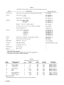
Measurement Mode: Measures R series or parallel; L and Q series or parallel; C
and D series or parallel. All measurement modes are pushbutton selectable.
Ranges: Pushbutton selection with automatic front-panel guidance. Three basic ranges
(best accuracy, see table) of 2 decades each, for each parameter. Automatic extensions
to min and max, as tabulated.
Displays: LED-type numerical display with automatically positioned decimal points
and illumination of units. For R LC, five digits (99999) and simultaneously for DQ,
four digits (9999).
Measurement Speed: Greater than 3 measurements per second.
/
Test frequencies: Pushbutton selection between 2. Accuracy re panel
legends: +2%, -.01%. Actual frequencies: for 1657-9700, 1020.0 Hz +/- .01% (panel
legend "1 kHz") and 120.00 Hz +/- .01%;
for 1657.9800,1000.0 and 100.00 Hz +/- .01%.
Applied Voltage: 0.3 V rms maximum.
Accuracy: For R, L, and C: +/- 0.2% of reading in basic ranges, if quadrature
component is small (D < 0.1, Q > 10, etc). See table. D accuracy: +/- .001 in basic
ranges, for D < 0.1 (otherwise, see table). Q accuracy: +/-.01 in basic ranges, for Q < 1
(otherwise, see table).
Environment: TEMPERATURE: 0° to 50°C operating, -40° to +75°C
storage. HUMIDITY: 0 to 85% R.H., operating.
Supplied: Power cord, axial-lead adaptors, instruction manual.
Power: 90 to 125 or 180 to 250 V, 50 to 60 Hz. Voltage selected
by rear-panel switch. 25 W maximum.
Mechanical: Bench mounting. DIMENSIONS: (wxhxd): 375x112x343 mm
(14.8x4.4x13.5 in.). WEIGHT: 5.6 kg (12.3 lb) net,l0 kg (22 lb) shipping.
Patent applied for.
SERVICE POLICY
QuadTech policy is to maintain product repair capability for a period of five (5) years after original
shipment and to make this capability available at the then prevailing schedule of charges.
Table of Contents
1.1 PURPOSE
1.2 GENERAL DESCRIPTION
1.3 CONTROLS, INDICATORS, AND CONNECTORS
1.4 ACCESSORIES
1.1 PURPOSE.
The 1657 Digibridge digital impedance meter embodies
use of a microprocessor and other LSI circuitry to
provide excellent performance at low cost.
A few clearly labeled pushbuttons and the versatile
built-in test fixture make this instrument a model for convenience. Measurement results are clearly shown with decimal points and units, which are automatically presented to
assure correctness. Display resolution is 5 digits for R, C,
and L (4 for D or Q) and the basic accuracy is 0.2%.
Long-term accuracy and reliability are assured by the
measurement system. It makes these accurate analog
measurements over many decades of impedance without a
single calibration or "trimming" adjustment (not even in
original manufacture).
The built-in test fixture, with a pair of plug-in adaptors,
1-1
1-1
1-1
1-1
in keeping with the long-life circuitry inside. Glass-epoxy
circuit boards interconnect and support high-quality com
ponents to assure years of dependability.
Adaptability to any common ac power line is assured by
the removable power cord and the convenient line-voltage
switch. Safety is enhanced by the fused, isolating power
transformer and the 3-wire power connection. A compre
hensive functional description is given in Theory, Section 4
Electrical and physical characteristics are listed in Specifi
cations at the front of this manual, dimensions in Installa
tion, Section 2. Controls are described below, and their use
in Operation, Section 3.
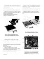
1.3 CONTROLS, INDICATORS, AND CONNECTORS.
.
Figure :-1 shows the front panel conrols and indicators.
receives any common component part (axial-lead or radial-
Table 1-1 identifies them with descriptions and functions.
lead) so easily that insertion of the DUT is a one-hand
.
.
.
operation.
True 4-terminal connections
are made automat
I
t
.
ically. Extender cables and other accessories are available
Similarily,
Figure
1-2 shows
rear
panelcontrols
and Table
identifies
describes
thethe
rear
panel
and1-2
connec
Identifies and
and describes the rear panel controls and connectors.
for measurements at a distance from the Digibridge.
1.2 GENERAL DESCRIPTION.
Convenience is enhanced by the arrangement of test
fixture on the front ledge, with push buttons farther forward and display behind. The display panel is inclined and
recessed to enhance visbility of digital readouts and mode
indicators. These indicators serve to inform and guide the
operator as he operates the simple controls.
The instrument stands on a table or bench top. The
sturdy metal cabinet is attractively and durably finished,
1.4 ACCESSORIES.
Gen Rad makes several accessories that enhance the use
fulness of this instrument. Two extender cables facilitate
making connections to those devices and impedance stan
dards that do not readily fit the built-in test fixture. A
remote test fixture (used with BNC adaptor and cable
assembly) provides convenience and relatively easy main
tenance, and saves wear on the built-in test fixture. All of
these test-fixture accessories provide for true 4-terminal
connections (and guard) to the device being measured,
without appreciable reduction in measurement accuracy.
Other useful accessories are offered, such as standards for
checking the performance of the Digibridge. Refer to
Table 1 -3 and Section 5.
INTRODUCTION 1-1
1-2 INTRODUCTION
INTRODUCTION 1-3
1-4 INTRODUCTION
2.1 UNPACKING AND INSPECTION.
If the shipping carton is damaged, ask that the carrier's
agent be present when the instrument is unpacked. Inspect the instrument
for damage (scratches, dents, broken parts, etc.). If the instrument is
damaged or fails to meet specifications, notify the carrier and the nearest
GenRad field
office. (See list at back of this manual). Retain the shipping carton and the
padding material for the carrier's inspection.
2.2 DIMENSIONS
Figure 2-1.
The instrument is supplied in the bench configuration,
i.e., in a cabinet with resilient feet for placement on a table. The overall
dimensions are given in the figure.
2.3
POWER-liNE CONNECTION.
The power transformer primary windings can be switched, by means of
the line voltage switch on the rear panel, to ac. commodate ac line voltages
in either of 2 ranges, as labeled, at a frequency of 50 or 60 Hz, nominal.
Using a small screwdriver, set this switch to match the measured voltage of
your power line.
The instrument is fitted with a power connector that is in conformance
with the International Electrotechnical Commission publication 320. The 3
flat contacts are surrounded by a cylindrical plastic shroud that reduces the
possibility of electrical shock whenever the power cord is being unplugged
from the instrument. In addition, the center ground pin is longer, which
means that it mates first and disconnects last, for user protection. This panel
connector is a standard 3-pin grounding-type receptacle, the design of which
has been accepted world wide for electronic instru. mentation. The connector
is rated for 250 V at 6 A. The receptacle accepts power cords fitted with the
Belden type SPH-386 connector.
The associated power cord for use with that receptacle, for line voltages
up to 125 V, is Gen Rad part no. 4200-9625.
It is a 210-cm (7 ft), 3-wire, 18-gage cable with connector bodies molded
integrally with the jacket. The connector at the power-line end is a stackable
hammerhead design that conforms to the "Standard for Grounding Type
Attachment Plug Caps and Receptacles," ANSI C73. 11-1966, which
specifies limits of 125 V and 15 A. This power cord is
listed by Underwriters Laboratories, Inc., for 125 V, 10 A.
If the fuse must be replaced, be sure to use a "slow blow" fuse of the
current and voltage ratings shown on the rear panel, regardless of the line
voltage.
I f your I ine voltage is in the lower range, connect the 3-wire power
cable (P/N 4200-9625) to the power connector on the rear panel (Figure 1-2)
and then to the power line.
INSTAllATION 2-1
If your line voltage is in the higher range selectable by the line voltage
switch, use a power cord of the proper rating (250 V, 15 A) that mates
with both instrument and
your receptacle. It is possible to replace the "hammerhead" connector on the
power cord that is supplied with a suitable connector. Be sure to use one
that is approved for 250 V, 15 A. A typical configuration is shown in Figure
2-2.
2.4 LINE-VOLTAGE REGUlATION
The accuracy of measurements accomplished with precision electronic
test equipment operated from ac line
sources can often be seriously degraded by fluctuations in primary input
power. line-voltage variations of +/-15% are commonly encountered, even
in laboratory environments.
Although most modern electronic instruments incorporate some degree of
regulation, possible power.source problems should be considered for
every instrumentation setup. The use of line-voltage regulators between
power lines and the
test equipment is recommended as the only sure way to rule out the effects
on measurement data of variations in line voltage.
2.5 TEST-FIXTURE CONNECTIONS.
2.5.1 Test Fixture on the Digibridge.
Because an unusually versatile test fixture is provided on the front shelf
of the instrument, no test-fixture connection is generally required. Simply
plug the device to be measured (DUT) into the test fixture, with or without
its adaptors. For details, refer to paragraphs 3.1, 3.2. Accessories can be
attached to extend and adapt the test fixture, as described below.
2.5.2 Remote Test Fixture.
Connection of the DUT at a remote test fixture requires proper adaptors
and cable connections from the Digibridge. Obtain the following
accessories. (See Table 1-3.)
BNC Adaptor 1689-9601
BNC Cable Assembly 1689-9602, or equivalent
Remote Test Fixture 1689-9600, or equivalent
handler or special fixture.
2-2 INSTAllATION
This remote test fixture functions like the one supplied on the
Digibridge. True "Kelvin" connections are made at the points of contact
with the DUT leads. Install as
follows:
a. Remove any adaptors, if present, from the test
fixture.
b. Plug the BNC adaptor into the basic test fixture with the BNC
connectors facing forward. lock the connection with the 2 captive thumb
screws. (The screws must be
seated to complete the ground connection.)
c. Connect the cable assembly to the adaptor on the Digibridge and to
the remote test fixture as indicated in Table 2-1.
NOTE
User provided cables and/or remote test
fixtures can be used, particularly if the
DUT is to be handled automatically.
See paragraph 3.7 for comments on cable
and fixture capacitance.
2.5.3 The 1657-9600 Extender Cable (Banana Plugs).
The accessory extender cable 1657-9600 is available to connect to
DUTs that are multiterminal, physically large, or otherwise unsuited for
the built-in test fixture. This cable is particularly convenient for connecting
multiterminal components with binding posts that accommodate banana
plugs. Use the following procedure to install the extender cable on the
instrument.
a. Remove the adaptors, if present, from the test
fix tu re.
b. Plug the single-connector end of the extender cable into the
Digibridge test fixture so that its blades enter both slots and the cable lies
away from the display panel. lock the connector with the two captive
thumb screws.
c. Note the color coding of the five banana plugs. Be sure that the
"low" terminals (both potential and current) connect to one end of the
DUT and the "high" terminals to the other end. Connect guard to a shield if
any, but not to either end of the DUT.
P-(potential, low) = Black/white
I-(current, low) = Black
P+(potential, high) = Red/white
I+(current, high) = Red
Guard = Black/green
2.5.4 The 1688-9600 Extender Cable
("Type 874" Connectors).
The accessory extender cable 1688-9600 can be used to connect a
DUT that is multiterminai, physically large, or otherwise unsuited for the
built-in test fixture. This
low-capacitance cable is used, for example, to connect type-874
connected impedance standards or a special
test fixture. Make connections as follows:
a. Remove the adaptors, if present, from the test fixture.
b. Plug the single-connector end of the extender cable into the
Digibridge test fixture so that its blades enter both slots and the cable lies
away from the display panel. Lock the connector with the two captive
thumb screws.
c. Using the branched end of the cable, connect to the DUT with
careful attention to the following color code.
The cable tips are type 874 coaxial connectors, which
mate with a broad line of components and adaptors.
Notice that the 2 wires with red must connect to the same end of the
DUT, through a coaxial tee if the DUT is a 2-terminal device; the 2
wires labeled with black, connect to the other end, similarly. Connect
the outer (shield) contacts to the shield or case of the DUT only if it
is isolated from both ends of the DUT.
EXTENDER CABLE COLOR CODE
RED AND RED: 1+, current drive to
"high" end of DUT.
RED AND WHITE: P+, potential connection
to same.
BLACK AND BLACK' I-, current return at
DUT "low".
BLACK AND WHITE: P-, potential
connection to same.
OUTER CONTACTS: G, guard connection
to shield or case.
2.6 EXTERNAL BIAS.
Figure 2-3.
WARNING
To minimize electrical shock hazard, limit
bias to 30V.
Bias voltage is present at connectors, test
fixtures and on capacitors under test.
Capacitors remain charged after measurement.
Do NOT leave instrument unattended with bias
applied.
Full bias voltage appears on test leads, bias-voltagesource terminals,
and on the leads of the component being measured. Capacitors that have
been charged are dangerous until properly discharged; the user must follow
safe procedures to assure discharge. For safety, all personnel operating the
instrument with bias must be aware of the hazards, follow safe procedures,
and never leave the equipment unattended with bias voltage applied.
2.6.1 Basic Bias Connections.
In order to measure a capacitor with dc bias voltage
applied, connect an external voltage source, as follows:
a. Attach the remote test fixture or an extender cable as described in
paragraph 2.5. Observe the color coding explained there.
INSTALLATION 2-3
b. Connect a suitable bias voltage source (see below)
in series with the 1+ connection, basically as shown in
the diagram, with the following details.
With the Remote Test Fixture. Disconnect the red coded BNC cable end
from the remote test fixture and connect one end of plain BNC cable there
instead.
Connect the red coded BNC cable end to the negative terminal of the bias
voltage source. Connect the remaining free end of the plain BNC cable to
the positive terminal of the bias voltage source. Connect the DUT to
the test fixture in the usual way.
With 1657-9600 Extender Cable (Banana Plugs). Connect the red
banana plug to the negative terminal
of the bias voltage source. Connect a suitable banana
plug patch cord to the positive terminal. We designate
the free end of this patch cord as I++, as shown in the
diagram.
With 1688-9600 Extender Cable
("Type 874 Connectors").
Connect the "red and red" cable to the negative terminal of the bias voltage
source. Connect a suitable type-874 patch cable to the positive terminal.
We designate the
free end of this patch cable as I++, as shown in the diagram.
c. If either of the extender cables (not the remote test fixture) is used,
connect the DUT as follows. If capacitance is large (range 1), make 2
connections to each capacitor terminal (Kelvin connections). That is, I- and
P- to capacitor negative terminal; P+ and I++ to capacitor positive
terminal.
If the capacitance is smaller (range 2 or 3) the banana plugs can be
stacked or a tee used with type-874 connectors
and a single connection made to each capacitor terminal: I- /P- to the
negative terminal, P+/I++ to the positive.
To make 3-terminal (or 5-terminal) measurements, also connect guard
(see paragraph 2.5) to the guard terminal, shield, case, or ground of the
capacitor, provided that this is insulated from the 2 main terminals of the
capacitor. Do not connect guard to the case of a capacitor if the case is one
of its 2 main terminals.
2.6.2 Bias Voltage Source Description
The bias voltage source must satisfy several criteria:
1. Supply the desired terminal voltage (dc)
2. Serve as source for charging current.
3. Serve as source and sink for the measuring currents
(ac), which are 45, 0.45, and .0045 mA, peak, for measurements on ranges
1, 2, and 3, respectively.
4. Present a low, linear terminal impedance (< < 10 ohms)
at measuring frequency.
If the bias voltage source is a regulated power supply
with the usual characteristic that it functions properly only as a source, not
a sink, then the following test setup is
2-4 INSTAllATION
recommended. Connect across the power supply a bleeder resistor that
draws dc current at least as great as the peak measuring current (item 3
above). In parallel with the bleeder, connect a 100-pF capacitor. (If the
power supply has exceptionally good transient response, the capacitor is
not necessary.)
No single bleeder resistor will suffice for all bias conditions, so it may
be necessary to switch among several. Each resistance must be small
enough to keep the power supply regulator current unidirectional (as
mentioned above) for the smallest bias voltage in its range of usefulness.
Also the resistance and dissipation capacity must be large enough so that
neither the power supply is overloaded nor the resistor itself damaged for
the highest bias voltage in its range of application.
NOTE
For convenience, a suitable active current sink
can be used in lieu of bleeder resistors.
A discharge circuit is also required. (Do not depend on the abovementioned bleeder resistor.) A dual discharge circuit is recommended.
Connect a clip lead with a 10-Q resistor in series and another plain clip lead
to the I-/Pjunction. Provide the loose ends of these with insulated alligator
clips for use when completing the discharge path across the DUT. For a
recommended procedure, refer to para 3.6.
I f the measurement program warrants the expense of a test fixture for
biased-capacitor measurements, its function should be equivalent to that of
the circuit described above. It should be equipped with convenient
switching to remove the bias source, discharge through 10 Q, and finally to
short out the capacitor after measurement. For automated test setups, it is
also feasible to precharge the capacitors before they are attached to the test
fixture and to discharge them after they have been removed.
CAUTION
To avoid damage to the instrument, limit the bias voltage to 30 V,
maximum, in any precharging
bias supply, used as mentioned above.
2.7 ENVIRONMENT.
The Digibridge can be operated in nearly any environment that is
comfortable for the operator. Keep the instrument and all connections to
the parts under test away from
electromagnetic fields that may interfere with measurements.
Refer to the Specifications at the front of this manual for temperature
and humidity tolerances. To safeguard the instrument during storage or
shipment, use protective packaging. Refer to Section 5.
OPERATION 3-1
3.1 BASIC PROCEDURE.
Figure 3-1.
For initial familiarization, follow this procedure care
fully. For details, refer to later paragraphs in Operation.
a. Before connecting the power cord, slide the linevoltage switch (rear
panel) to the position that corresponds to your power-line voltage. Power must
be nominally either 50 or 60 Hz ac, either 120 or 220 V. (Refer to
specifications at front of this manual.) The 1657-9700 can be run on 50 Hz but
with some loss of accuracy for 120-Hz measurements in high range
extensions. Similarly, the 1657-9800, if run
on 60-Hz power, experiences some extraneous noise in 100Hz
measurements in high range extensions.
If the fuse must be replaced, be sure to use a "slow
blow" fuse of the rating shown on the rear panel.
b. Connect a typical device, whose impedance is to be
measured, as follows. (This device under test is denoted DUT.)
NOTE
Clean the leads of the DUT if they are notice
ably dirty, even though the test-fixture contacts
will usually bite through a film of wax to pro
vide adequate connections.
Radial-lead DUT: I nsert the leads into the test.fixture
slots as shown in the photograph, Figure 1-1. For details of wire size and
spacing limits, refer to para 3.2.
Axial-lead DUT: Install the test-fixture adaptors, supplied, one in
each slot of the test fixture, as shown in the accompanying figure. Slide
the adaptors together or apart
so the body of the DUT will fit easily between them. Press the DUT down
so that the leads enter the slots in the adaptors as far as they go easily. For
details of wire size and DUT size limits, refer to para 3.2.
NOTE
To remove each adaptor, lift with a gentle tilt
left or right. For a DUT with very short leads
it is important to orient each adaptor so its internal contacts
(which are off center) are close
to the DUT.
Other DUTs, Remote Connections, and Bias.
For connections via extender cables and remote
test fixtures, refer to the installation instructions of paragraph 2.5. For
connection of bias voltage and operating procedures with bias, refer to
paragraphs 2.6 and 3.6. For convenience, the typical color coding used in
extender cables is repeated below.
Red: I+, current connection to "high" end of DUT. ,
Red & white: P+potential connection to same.
Black: I-, current connection to low endof DUT. .
Black & white: P-, potential connection to same
Black & Green: G, guard connection to shield or case (if isolated
from the preceding terminals). Do not-connect G to the case of a capacitor
if the case serves as (or is connected to) one of its 2 main terminals.
3-2 OPERATION
Notice that the 2 red tips must connect to the same end of the DUT. The
terminals with white bands are potential connections; with no bands, current
terminals.
c. Set.the pushbuttons according to the desired measure
ment, as follows:
Power. Depress the POWER button so that it stays in the depressed
position. (To turn the instrument off, push and release this button so that it
remains in the released position.)
Function. For resistance, depress R. For inductance, depress L/Q. For
capacitance, depress C/D. Be sure that one of these buttons is in the
depressed position.
Frequency. For measurement at 1 kHz, push and release the
FREQUENCY button until the 1-kHz light comes on. For 120 (100) Hz, push
the same button so that the 120-Hz (100.Hz) light comes on.
Parallel or Series. For series equivalent circuit, push and release the
PARALLEL/SERIES button until the SERIES light comes on. For parallel
equivalent circuit, push this button so that the PARALLEL light comes on.
(The choice is significant for lossy capacitors or inductors, not for lowloss
reactive components or non-reactive resistors.) For further explanation, refer
to para 3.5.
Range. Depress the middle (RANGE-2) button first and watch the
ADJUST RANGE lights. If the right-pointing arrow is lighted, depress
RANGE button at the right. If the left-pointing arrow is lighted, depress
RANGE button at the left. When neither arrow is lighted, the range you have
selected is correct. (Be surc that one of the RANGE buttons is in the
depressed position.) Additional comments on range choices are below.
d. Read the measurement on the main displays. The
R LC display is the principal measurement, complete with decimal point and
units, which are indicated by the light spot behind MΩ, kΩ, Ω, H, mH, nF,
or uF.* The DQ display is D if the C/D FUNCTION button is in, Q if the
L/Q button is in.
e. After any change in DUT or measurement conditions, before looking
at the displays, notice the ,ADJUST RANGE
lights. Interpret them as follows:
Neither light. Correct range. (There are minor exceptions.)
Left Light. Wrong range; try next RANGE button to left.
Right Light. Wrong range; try next RANGE button to
right.
Both Lights. Overrange or invalid display. If FUNCTION is correct
and RANGE is highest, the measurement is valid but because of an
overrange condition, the basic 0.2% accuracy cannot be guaranteed. (If you
switch to RANGE 2, one
of the lights will go out.) If both lights are lit on RANGE 2, either the
FUNCTION is inappropriate for the DUT or it is not properly connected.
For more details, refer to para 3.3.
*If the extender cable is used. it may be necessary to correct for its
capacitance.
3.2 CONNECTION OF THE DUT.
3.2.1 The Integral Test Fixture.
The test fixture provided on the front ledge of the Digi
bridge provides convenient, reliable, guarded 4-terminal connection to
any common radial-lead or axial-lead component.
If the slots of your test fixture have rounded ends, the
slots accommodate wires of any diameter from 0.25 mm (.01 in., AWG
30) to 1 mm (.04 in., AWG 18), spaced from 6 to 98 mm apart (0.23 to 3.9
in.) or equivalent strip conductors. Each "radial" wire must be at least 1 cm
long
(0.4 in.). However, if the slots of your test fixture have square ends, they
will accommodate wires spaced as close as 4 mm (0.16 in.) and each
"radial" wire must be at least
4 mm (0.16 in.) long. The divider between the test slots contains a shield, at
guard potential, with its edges exposed. The adaptors accomm odate wi res
of any diameter up to 1.5 mm (.06 in., AWG 15). The body of the DUT that
will fit between these adaptors can be 80 mm long and 44 mm diameter
(3.1x1.7 in.) maximum. Each "axial" wire must be at least 3 mm long (0.12
in.).
For radial-lead parts, remove each adaptor from the test fixture by a
gentle pull upward, made easier by bending the adaptor left or right (never
forward or back). For axial-lead parts, insert the adaptors, one in the left
slot and the other
in the right slot of the test fixture, by pushing vertically downward. They
can be slid left and right to match the length of DUT to be measured. Notice
that the contacts inside the adaptor are off center; be sure to orient the
adaptors so the contacts are close to the body of the DUT, especially if it
has short or fragile leads.
Insert the DUT so one lead makes connection on the
left side of the test fixture, the other lead on the right side. Insertion and
removal are smooth, easy operations and connections are reliable if leads
are clean and straight.
Be sure to remove any obvious dirt from leads before inserting them.
Be sure the contact pair inside each half of the test fixture is held open by a
single item ONLY, whether that is one lead of an axial-lead DUT or one
adaptor, to obtain true "Kelvin" connections.
3.2.2 Test Fixture Accessories.
An accessory extender cable or adaptor, cable, and remote test fixture,
as described in Table 1-3, is needed
to connect any DUT that is multiterminal, physically
large, or otherwise unsuited for the built-in test fixture.
A cable is needed, for example, to connect impedance standards, a
remote test fixture, capacitors to be measured with bias, etc. For
connection to the instrument, refer to paragraph 2.5. For
measurements with bias,
refer to paragraphs 2.6 and 3.6. The color code for the branched end
of each cable is given in paragraph 3.1. To correct for cable
capacitance, refer to paragraph 3.7.
3.3 FUNCTION AND RANGE SELECTIONS.
3.3.1 Function Pushbuttons.
The selection of the principal parameter to be measured is almost selfexplanatory. Depress the appropriate FU NCTION button: R, L/Q or C/D to
measure resistance, inductance, or capacitance. The instrument will tolerate,
to some degree, a poor choice of function, but accuracy is thereby reduced.
The readout will indicate a completely wrong choice of function, as
explained below. Notice that the appearance of a device can be misleading.
(For example, a faulty inductor can be essentially capacitive or resistive;
a component part can be mislabeled or unlabeled.)
If both ADJUST RANGE lights are on, the RANGE 2 button is in, the
RLC display is blank, and the DUT is properly connected, then the choice
of function is probably wrong. Most likely, if the L/Q button is in, the DUT
is capacitive; or if the C/D button is in, the DUT is inductive.
Observe the DQ display for an indication of poor choice of function
(though tolerable). Large D or small 0 may indicate that the "reactor" being
measured is practically a
resistor at the measuring frequency. If the C/D button is in and the D
reading is between 1 and 10 (or blank, as it will be for D> 10) it is
possible that the DUT is eno,ugh like a resistor to be measured best
with the R button in. Similarly, if the L/Q button is in and the Q reading
is
between zero and 1, it is possible that the DUT is enough like a resistor to
be measured best with the R button in. Notice that when the R button is in,
the DO display is always blank. On the other hand, any D or Q display is
valid, even if the "wrong" function has been selected. (The C or L display
can be blank.)
If the R button is in (a resistor is being measured) the easy way to
determine whether the DUT is reactive is to try making C/D and L/Q
measurements. If you obtain a valid C measurement with D < 1, the DUT is
capacitive. The smaller this D value, the less accurate the R measurement.
Similarly, if you obtain a valid L measurement with Q > 1, the DUT is
inductive. The larger this Q value the less accurate the R measurement. (See
para 3.4.)
3.3.2 Range Pushbuttons.
Range selection is also nearly self-explanatory. Follow the ADJUST
RANGE lights. The left light means: "Push the next range button to the
left." The right-hand light
means: "Push the next range button to the right." Continue until both lights
go out. The instrument will usually display a measurement (at reduced
accuracy) even though the range is not optimum. The following details
about range are best
understood with reference to para 3.4 (particu1arly the RLC basic accuracy
graph).
The RANGE buttons are placed in order of decreasing impedance, 3-21. The "highest" range is therefore Range 1
for C/D; but it is Range 3 for Rand L/Q.
OPERATION 3-3
Each basic range is slightly more than 2 decades wide, from an R LC
display of 01900, with an automatic decimal
point change between the decades, to 19999. (The symbol 0 represents
a blanked zero. Initial zeroes to left of the decimal point are always blanked
out of the RLC display.) Each of the 3 ranges goes beyond its basic range,
with both upper and lower range extensions (shown by lighter lines in the
RLC basic accuracy graph). Several of these extensions are seldom used
because they overlap "basic" portions of other ranges and because the
operator is alerted to this fact by an ADJUST RANGE light.
Each range includes 2 or 3 subranges, distinguished by the automatic
decimal-point shift. The operator does NOT control them. Subranges are
detailed in Table 3-1. Notice, for example, if you select RANGE 1, C/D, 1
kHz, then there are 2 subranges: 19uF and 999uF. If a series of measurements is made with C increasing slowly above 19uF, the automatic
subrange change takes place at 21. But with C decreasing, the change takes
place at 20. This hysteresis eliminates a possible cause of flickering of the
display.
The "low" extension of each range goes from 01900 down to 00000,
without any change in decimal point, but with reduced accuracy. The
number of digits in this display is always adequate for the specified
accuracy. Any measurement in the low extension of either Range 2 or the
highest range causes the appropriate ADJUST RANGE arrow to be lighted.
But there is no such light in the low extension of the lowest range (because
there is no lower range to select).
The "high" extension of each range is a factor of 5 (with 2 exceptions),
going from 19999 up to 99999, and finally to blank, without any change in
decimal point, but with reduced accuracy. Any measurement in the high
extension of either the lowest range or Range 2 causes the appropriate
ADJUST RANGE arrow to be lighted. However in
3-4 OPERATION
the high extension of the highest range, both ADJUST RANGE arrows are
lighted (to indicate a useful "overrange" condition) .
The high extension of the top range for Rand C only, at 120 Hz (100
Hz) only, is a factor of 50, going from 19999, with an automatic decimalpoint change, up to 99999, and finally to blank, with reduced accuracy.
(Both ADJUST RANGE arrows are lighted as described above.)
A special case warrants explanation. (This is a minor exception to the
basic procedure of para 3.1.) It is possible
for both ADJUST RANGE lights to be out and yet the RANGE and
FUNCTION buttons to be incorrectly set.
This condition result's from either faulty connection to the DUT or a
numerically small negative Lor C measurement. Sometimes a loose or dirty
connection to the DUT causes
an erratic RLC display. A small negative L or C (wrong function
selected) causes a zero display. In either case, check connections at the test
fixture and try all 3 FUNCTIONS to see which is appropriate, R, L/Q, or
C/D.
3.4 ACCURACY.
3.4.1 Graphs.
Figures 3-2, 3-3, and 3.4
The following accuracy graphs supplement the statement of accuracy in
the specifications, at the front of this manual.
Figure 3.2 shows that the R LC basic accuracy of 0.2% is realized over
6 decades of impedance if the correct range
is selected (as indicated by the ADJUST RANG E lights being out).
The reduction of accuracy is shown for all of the "low" and "high" range
extensions. This basic RLC accuracy is valid only for "pure" R. L, or C.
For the effect
Figure 3-2. R L C basic accuracy as a percent of reading. Heavy lines (solid and dotted) represent best
choice of range. Range 2 is dotted. Notice that Land C scales above graph are for 120 Hz (*equally valid for
100 Hz) and the 2 below graph are for 1 kHz. The DQ accuracy factor (right-hand scale) is the multiplier
that, applied to the DQ Basic Accuracy, yields complete DQ accuracy, for range extensions as well as the
basic ranges (where RLC accuracy is 0.2%).
of quadrature impedance, multiply each basic accuracy value by the RLC
accuracy factor; see below.
Figure 3-3 shows the RLC accuracy factor, which depends on D or Q.
For example, suppose a capacitor measured at
1 kHz has C = 400 uF and D = 0.5. The R LC basic accuracy is 0.4% and
the R LC accuracy factor is 1.5. Therefore, the accuracy of the C
measurement is :+/-0.6%. Notice that the
D or Q of a resistor (if significant) can be measured by selecting the C/D or
L/Q FUNCTION.
Figure 3-4 shows the basic DQ accuracy, which is simple function of
D or Q. For D read the lower scale and lower curve. For Q read the upper
scale and upper curve. The basic DQ accuracy is valid only if
measurements are made on one of the 3 basic ranges (where RLC
accuracy
is best). Otherwise, multiply basic DQ accuracy by the DQ accuracy
factor, shown on the right of the "RLC basic accuracy" graph. In the
example of C = 400 uF, D = 0.5, the basic D accuracy is 0.5% and the D
accuracy factor is 2. Therefore, the accuracy of the D measurement is :+/-1%
OPERATION 3-5
The logarithmic scales on these figures make it very easy to apply the
accuracy factors visually. For example, suppose a capacitor is being measured
on range 2, both ADJUST RANGE lights are out, and the D display' is about
1. Figure 3-3 shows that the C accuracy factor is about 1/3 of a decade on the
logarithmic scale. On Figure 3-2, find the heavy dotted line (the basic portion
of range 2) and point to the basic C accuracy (0.2%) at the left. Now apply the
C accuracy factor by moving the pointer up about 1/3 of a decade. The pointer
now shows the corrected C accuracy, 0.4%.
3.4.2 Insignificant Digits.
One or more of the digits at the right end of the R LC and/or DQ displays
may be insignificant. This is particularly true at the upper extension of a
range. If there are more than one insignificant digits in a display, the least
significant is typically noisy. That is, it will appear to flicker at random over a
range of values and should be ignored.
For example, if you measure a 4-MΩ resistor, the display might ideally
be 4.1234 MΩ; but the one or two final digits might be changing at random.
This flickering is entirely normal. The specified accuracy (+/-0.4%) is the key
to expected performance; in this example, the last 2 digits are insignificant
and the last digit is quite unnecessary. Typically, one would record this
measurement as 4.12 +/-.02 MΩ.
specify with your results whether they are "parallel" or "series" and what the
measurement frequency was.
Resistors, below about 1 kΩ: Series, 120 Hz (100 Hz). Usually the
specifications call for dc resistance, so select a low test frequency to
minimize ac losses. Select "series" because the reactive component most
likely to be present in a low-resistance resistor is series inductance, which
has no effect on the measurement of series R. As a quick check on whether
the DUT is nearly pure resistance, make a separate "parallel" measurement.
Rp will be larger then Rs. If the difference is less then 1 %, then 0 is less
than 0.1, and the measured Rs is probably very close to the dc resistance.
Resistors, above about 1 kΩ: Parallel, 120 Hz (100 Hz). As
explained above, select a low test frequency. Select "parallel" because the
reactive component most likely to be present in a high-resistance resistor is
shunt capacitance, which has no effect on the measurement of parallel R. As
a quick check on whether the DUT is nearly pure resistance, make a
separate "series" measurement. If the difference between Rp and Rs is less
than 1%, then D is greater than 10, and the measured Rp is probably very
close to the dc resistance.
Capacitors below 2 nF: Series, 1 kHz. Unless otherwise specified or for
special reasons, always select "series"
for capacitors and inductors. This has traditionally been standard practice.
Select a high measurement frequency for best accuracy.
3.5 PARALLEL/SERIES AND FREQUENCY SELECTIONS.
Capacitors above 200 uF: Series, 120 Hz (100 Hz). Select "series" for
3.5.1 General.
The value of the principal measurement (R, L, or C) of a certain DUT
depends on which of 2 equivalent circuits is chosen to represent it. (Many
impedance measuring instruments provide no choice in the matter, but this
one allows selection.) The more nearly "pure" the resistance or reactance, the
more nearly identical are the "series" and "parallel" values. However, for D
or 0 near unity, the difference is substantial. Also, the principal measurement
often depends on measurement frequency. The more nearly "pure" the
resistance or reactance, the less is this dependence. However, for D or Q near
unity and/or for measuring frequency near the self-resonant frequency of the
DUT, this dependence
is quite substantial. We first give general rules for selection of measurement
parameters, then some of the theory.
3.5.2 Rules.
Specifications. The manufacturer or principal user of the DUT probably
specifies how to measure it. (Usually "series" is specified for C, L, and low
values of R.) Select "parallel" or: "series" and 1 kHz or 120 Hz (100 Hz)
according to the applicable specifications. If there are none known, be sure
to
3-6 OPERATION
the reasons given above. Select a low measurement frequency for best
accuracy and to enable measurement of capacitors larger than 1000uF.
Inductors below 2 mH: Series, 1 kHz. Select "series"
as explained above. Select a high measurement frequency for best accuracy.
Inductors above 200 H: Series, 120 Hz (100 Hz). Select "series" as
explained before. Select a low measurement frequency for best accuracy
and to enable measurement of inductors larger than 1000 H.
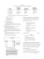
3.5.3 Series and Parallel Parameters.
Figure 3-5.
An impedance that is neither a pure reactance nor a pure resistance can
be represented at any specific frequency by either a series or a parallel
combination of resistance and reactance. Keeping this concept in mind will
be valuable
in operation of the instrument and interpreting its measurements. The values
of resistance and reactance used in the equivalent circuit depend on whether
a series or parallel combination is used. The equivalent circuits are shown in
Figure 3-5. The relationships between the various circuit elements are as
follows.
3.5.4 Equivalent Series R for Capacitors.
The total loss of a capacitor can be expressed in several ways, including
D and "ESR." To obtain equivalent series resistance, one can measure
directly (if D is high enough to permit the desired accuracy) or calculate.
Direct Measurement. If, while measuring C, you observe that D is
above 0.1 (or some other limit of your choice, see Figure 3-3), push
FUNCTION button R and select SERIES.
Both C and ESR should be measured on the same range. If D is below
1, the range should be correct for C, even though the ADJUST RANGE
light comes on while you measure ES R. However, if D is above 1, choose
the correct "R" range to obtain ESR; and then remeasure C on this range.
Calculation. If D is small, it is better to calculate "ESR" as follows: Rs
= D/2πfCs where π = 3.1416. D and Cs are displayed on the front panel.
Frequency f depends on the model of the instrument and the selected
frequency as follows (+/- .01%):
1657-9700: "1 kHz" is 1020.0 Hz; "120 Hz" is 120.0 Hz. 1657-9800: "1
kHz" is 1000.0 Hz; "100 Hz" is 100.0 Hz.
"Equivalent series resistance" is typically much larger than the "ohmic"
resistance of the wire leads and foils that are physically in series with the
heart of a capacitor. ESR includes also the effect of dielectric loss and is
therefore dependent on frequency.
3.5.5 Parallel Equivalent Circuits for Inductors.
Even though it is customary to measure series inductance of inductors,
there are situations in which the parallel equivalent circuit better represents
the physical device. At low frequencies, the significant loss mechanism is
usually "ohmic" or "copper loss" in the wire and the series circuit is
appropriate. If there is an iron core, at higher frequencies the significant
loss mechanism may be "core loss" (related to eddy currents and hysteresis)
and the parallel equivalent circuit is appropriate. Whether this is true at 1
kHz should be determined by an understanding of the DUT, but probably it
is so if the following is true: that measurements
of Lp at 1 kHz and at 120 Hz (100 Hz) are more nearly in agreement than
measurements of Ls at the same 2 frequencies.
3.6 BIAS.
To measure a capacitor with bias applied, it is necessary to insert a bias
voltage source in series with the I+ lead to the DUT and to provide a means
of discharging it. Refer to para 2.6 for installation of the recommended
circuit.
OPERATION 3-7
WARNING
To minimize shock hazard, limit bias to 30 V.
Bias voltage is present at connectors, test
fixtures and on capacitors under test.
Capacitors remain charged after measurement.
Do not leave instrument unattended with bias
applied.
a. Install an adaptor, GR 874-Q2, on each of the
two coaxial connectors, Land H, of the capacitor.
b. Connect cable branch G to the ground post of the "low" terminal
adaptor. With a clip lead or plain wire, connect this point to the ground post
of the "high" adaptor.
c. Connect cable branch P- to the main post of the
"low" adaptor and stack I- on top of P-.
d. Similarly, connect P+, with I+ stacked on top of it,
Although special precautions are not required, we recommend the
following procedure, to assure controlled
conditions for both charging and discharging. capacitors.
a. Set the bias voltage to zero.
b. Attach the DUT, with correct polarity.
c. Raise the bias voltage to the specified value.
d. Allowa specified charging and soaking time.
e. Observe and record the specified measurements
(usually Cs and D).
f. Set the bias voltage source to zero.
g. Connect the 10-n discharging circuit.
h. After about 2 s, connect the safety short circuit.
i. Remove the DUT and the discharging circuits.
to the main post. of the "high" adaptor.
e. Measure this total capacitance, the sum of the desired
measurement and the cable capacitance, Cx + Cc.
f. Carefully lift the stacked pair of cable tips, I+/P+, from the "high"
adaptor and hold them about 0.5 cm (1/4 in.) above the binding post where
they were connected.
Do NOT rearrange the cable branches or change their spacing more than is
absolutely necessary to follow these directions. Hold the plastic tips (not the
wires) and touch the guard (G) circuit firmly with a couple of fingers, to
minimize the
effect of capacitance in your body.
g. Measure the cable capacitance, Cc.
h. Subtract the result of step g from that of step e,
to obtain the desired measurement, Cx.
3.7 CORRECTION FOR TEST FIXTURE ACCESSORIES.
3.7.1 With the Remote Test Fixture.
The remote test fixture, cable assembly, and adaptor (1689-9600,
-9602, -9601) introduce about .001 nF of capacitance in parallel with
the DUT, a generally negligible error. For the best accuracy, select
PARALLEL, C/D, and range 3; measure the capacitance "Cc" with
the remote test fixture open (no DUT). Then measure a DUT, PARALLEL,
C/D; the RLC display is now
Cc + Cx, where Cx is the capacitance of the DUT. Therefore, subtract the
measured Cc from the R LC display to obtain Cx.
3.7.3. With the 1688-9600 Extender Cable
("Type 874" Connectors).
The 1688-9600 extender cable introduces no parallel capacitance that can
be resolved on the 1657 Digibridge, if the shielding between "high" and
"low" is maintained consistently. For example, to connect a 3-terminal DUT
having two type 874 connectors, use a type 874 tee for the red and red/white
cables, and another type 874 tee for the black and black/white cables.
3.8 CARE OF DISPLAY PANEL.
Use caution when cleaning the display window, not to scratch it nor to
get clean ing substances into the instrument. Use soft cloth or a ball of
3.7.2 With the 1657-9600 Extender Cable (Banana Plugs).
The 1657-9600 extender cable introduces about .0002 nF of capacitance
in parallel with the DUT, a negligible error. For very high precision, the
following procedure can be used,
determining a correction for measurements of parallel capacitance.
Because the physical arrangement and spacing of the cable branches and
connectors is significant, a correction should be determined for each
measurement setup. The following procedure applies to connection with a
precision 3-terminal capacitor, GR 1404 or 1413, for example:
3.8 OPERATION
absorbent cotton, moistened with a mild glass cleaner, such as "Windex"
(Drackett Products Co., Cincinnati, Ohio). Do NOT use a paper towel; do
NOT use enough liquid to drip or run.
If it should be necessary to place marks on the window, use paper-based
masking tape (NOT any kind of marking pen, which could be abrasive or
react chemically with the plastic). To minimize retention of any gummy
residue, remove the tape within a few weeks.
4.1 INTRODUCTION.
4.2 PRINCIPAL FUNCTIONS.
4.1 INTRODUCTION.
4.1.1 General.
This instrument uses an unusual method of measurement, which is quite
different from those used in previous impedance meters or bridges. A
thorough understanding of this method will be helpful in unusual
applications of the instrument. The following paragraph gives a brief overall
descrip. tion outlining the measurement technique to one familiar with
impedance measurement methods. A more detailed description of operation,
specific circuitry, and control signals is given later.
4.1.2 Brief Description of the 1657 Digibridge.
This Digibridge TM uses a new measurement technique, in which a
microprocessor calculates the desired impedance parameters from a series
of 8 voltage measurements.* These
measurements include quadrature (90°) and inverse (180°) vector
components of the voltage across the "unknown" impedance Zx and the
voltage across a standard resistor Rs
carrying the same current as Zx .Each of these measure
ments is meaningless by itself, because the current through
Zx is not controlled. But the 8 measurements are all made in rapid
sequence with the same phase-sensitive detector
and analog-to-digital converter. Therefore properly chosen differences
between these measurements subtract out fixed offset errors, and ratios
between the differences cancel out the value of the common current and
the scale factor of the detector-converter.
The phase-sensitive detector uses 4 reference signals, precisely 90°
apart, that have exactly the same frequency as the test signal, but whose
phase relationship to any of the analog voltages (such as the 8 mentioned
above) or currents (such as the current through Zx and Rs) is incidental.
Therefore, no precise analog phase shifter or waveform squaring circuit is
required. Correct phase relationships are maintained by generating test
signal and reference signals from the same high-frequency source.
There are no calibration adjustments in the Digibridge, thanks to the
measurement technique. The only precision
'Patent applied for.
4-1
4-2
components in this instrument are three standard resistors
and a quartz-crystal stabilized oscillator. There is no reactance
standard. For example, C and D are calculated by the microprocessor
from the set of 8 voltage measurements and predetermined values of
frequency and the
applicable standard resistance.
The microprocessor also controls the measurement sequence, using
programs in the ROM memory and a few manual selections. The desired
parameters, C and D, Land Q, or R; equivalent circ,.uit, series or parallel;
and frequency, either 120 Hz (100 Hz) or 1 kHz, are selected by front
panel controls. There are also three manually
selected ranges, which have wide overlap. The optimum range for
any measurement is indicated by panel lights.
Each range is 2 decades wide, with reduced-accuracy
extensions both above and below. For example, consider resistance
measurement on Range 1 (F igure 3-2). The 2 decades extend from
02.000 Ω, with an automatic decimal-point shift at 02.100 going up (at
020.00, going down) to 200.00 Ω. The range extensions go as far as
can be displayed without further decimal-point shifting: upwards to
999.99 Ω, downwards to 00.001 Ω. Leading zeroes before the decimalpoint (0) are blanked out.
Test frequencies are within 2% of the front-panel indication.
However, for reasons related to rejection of power-line-frequency stray
signals that could be picked up by the D UT, thereby causing
measurement errors, the actual frequencies are as follows --accurate to
:+/-.0l% catalog number 1657-9700: 1020.0 Hz, 120.00 Hz
catalog number 1657-9800: 1000.0 Hz, 100.00 Hz.
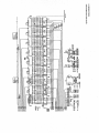
4.1.3 Block Diagram.
Figure 4-1.
The block diagram shows the microprocessor (uP) in
the upper right corner connected by data and address buses to digital
circuitry including RAM and ROM memories, status and control latches,
and the front-panel display.
Analog circuitry is shown in the lower part of the diagram, where Zx is
supplied with a test signal at frequency f from a sinewave generator, driven
by a crystal-controlled digital
frequency divider circuit. The front-end amplifier circuit supplies an analog
signal that represents 2 impedances alternately: the internal standard, Rs,
and the DUT, Zx.
THEORY 4-1
4-2 THEORY
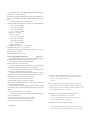
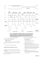
4.2.3 Sine-Wave Generation.
Figure 4-4.
Starting with a digital signal at 256 times the selected
test frequency, the sinewave generator provides the test signal that drives a
equally important are the generation of 4-phase references for detection and
small but essential current through the DUT.
clocks for the microprocessor. Frequency and timing requirements are
Binary dividers count down from 256 F, providing 128 F, 64 F, 32 F,... 2F,
implemented by derivation from a single very accurate oscillator, operating near
F. This set of signals is used to address a read-only memory which contains a
25 MHz. Digital dividers and logic circuitry provide the many clocks and
256-step approximation
triggers, as well as driving the sine-wave generator described below.
to a sine function. The ROM output (as an 8-bit binary number) is
converted by a D/A converter to a somewhat "noisy" sine-wave, which is then
smoothed by filtering before its use in the measurement of a DUT.
4.2.2 Frequency and Time Source.
Figure 4-3.
A necessary standard for accuracy is the frequency of the test signal; and
5.1 CUSTOMERSERVICE. .................................................................................................................... 5-1
5.2 INSTRUMENT RETURN.................................................................................................................. 5-1
5.3 REPAIR AND REPLACEMENT OF PLUG-IN BOARDS................................................................. 5-1
5.4 PERFORMANCE VERIFICATION................................................................................................... 5-2
5.5 MINIMUM-PERFORMANCE STANDARDS. ................................................................................... 5-2
5.6 DISASSEMBLY AND ACCESS. ...................................................................................................... 5-9
507 PERIODIC MAINTENANCE............................................................................................................ 5-11
5.8 TROUBLE ANALYSIS...................................................................................................................... 5-13
WARNING
These servicing instructions are for use by qualified personnel only. To avoid electrical
shock, do not perform any servicing, other than that contained in the operating instructions,
unless you are qualified to do so.
CAUTIONS
For continued protection against fire hazard, replace fuse only with
same type and ratings as shown on rear panel and in parts list.
cord ground wire, but must be connected to the work surface before, during,
and after any disassembly or other procedure in which the line cord is
disconnected. (Use a clip lead.)
Exclude any hand tools and other items that can generate a static charge.
Service personnel, observe the following precautions whenever you
handle a circuit board or integrated circuit in this instrument.
(Examples of forbidden items are nonconductive plunger-type solder suckers
and rolls of electrical tape.)
Ground yourself reliably, through a resistance, to the work surface; use, for
HANDLING PRECAUTIONS
FOR ELECTRONIC DEVICES
SUBJECT TO DAMAGE BY STATIC ELECTRICITY
example, a conductive strap or cable with a wrist cuff. The cuff must make
electrical contact directly with your skin; do NOT wear it over clothing.
(Resistance between skin contact and work surface through a commercially
available personnel grounding device is typically in the range of 250 kilohms to
Place instrument or system component to be serviced,
spare parts in conductive (anti-static) envelopes or carriers, hand tools, etc.
on a work surface defined as follows. The work surface, typically a bench
top, must be conductive and reliably connected to earth ground through a
safety
resistance of approximately 250 kilohms to 500 kilohms.
Also, for personnel safety, the surface must NOT be metal. (A resistivity of
30 to 300 kilohms per square is suggested.) Avoid placing tools or electrical
parts on insulators, such as books, paper, rubber pads, plastic bags, or trays.
Ground the frame of any line-powered equipment, test instruments,
1 megohm.)
If any circuit boards or IC packages are to be stored or transported,
enclose them in conductive envelopes and/or' carriers. Remove the items
from such envelopes only with
the above precautions; handle IC packages without touching the contact pins.
Avoid circumstances that are likely to produce static charges, such as
wearing clothes of synthetic material, sitting on a plastic-covered or rubberfooted stool (particularly while wearing wool), combing your hair, or making
extensive erasures. These circumstances are most significant
when the air is dry.
lamps, drills, soldering irons, etc., directly to
earth ground. Accordingly, (to avoid shorting out the safety resistance) be sure
that grounded equipment has rubber feet or other means of insulation from the
work surface. The instrument or system component being serviced should be
similarly insulated while grounded through the power
5-0 SERVICE
When testing static-sensitive devices, be sure dc power is on before,
during, and after application of test signals. Be sure all pertinent voltages have
been switched off while
boards or components are removed or inserted, whether hard-wired or plug-in.
5.1 CUSTOMER SERVICE.
all surfaces of the instrument. Insert fillers between pads and container to ensure
a snug fit. Mark the box "Delicate Instrument" and seal with strong tape or metal
Our warranty (at the front of this manual) attests the quality of
materials and workmanship in our products. If
bands.
Excelsior. Cover painted surfaces of instrument with protective wrapping
malfunction does occur, our service engineers will assist in any way possible.
paper. Pack instrument in strong corrugated container (350 Ib/sq in. bursting
If the difficulty cannot be eliminated by use of the following service
test), with a layer of excelsior about 6 in. thick packed firmly against all surfaces
instructions, please write or
of the instrument. Mark and seal the box as described above.
phone the nearest GenRad service facility (see back page), giving full
information of the trouble and of steps taken to remedy it. Describe the
instrument by name, catalog number, serial number, and 10 (lot) number if
any. (Refer to
front and rear panels.)
5.2 INSTRUMENT RETURN.
5.3 REPAIR AND REPLACEMENT OF CIRCUIT BOARDS.
This instruction manual contains sufficient information to guide an
experienced and skillful electronic technician in
fault analysis and the repair of some circuits in this instrument. If a
malfunction is localized to one board (or more) that is not readily repairable, it
can be returned to GenRad for repair. To save time, we recommend that you
obtain a replacement first, as described below, before returning the faulty board.
5.2.1 Returned Material Number.
Before returning an instrument to GenRad for service, please ask our
Exchanges. For economical, prompt replacement of any etched-circuit board,
order an exchange board. Its price is considerably less than that of a new one.
nearest office for a "Returned Material" number. Use of this number in
Place the order through your nearest GenRad repair facility. (Refer to the last
correspondence and on a tag tied to the instrument will ensure proper
page of this manual.) Be sure to request an exchange board and supply the
handling and identification. After the initial warranty period, please avoid
following information:
unnecessary delay by indicating how payment will be made, i.e., send a
1. Instrument description: name and catalog and serial numbers. Refer to
purchase-order number.
front and rear panels.
2. Part number of board. Refer to the parts lists in this manual. (The number
5.2.2 Packaging.
To safeguard your instrument during storage and shipment, please use
packaging that is adequate to protect it from damage, ie., equivalent to the
original packaging. Any GenRad field office can advise or provide packing
etched in the foil is generally NOT the part number.)
3. Your purchase order number. This number facilitates billing if the unit is
out of warranty and serves to iden
tify the sh ipment.
material
for this purpose. Contract packaging companies in many cities can
To prevent damage to the board, return the defective
provide dependable custom packaging on short notice. Here are two
board in the packing supplied with the replacement (or equivalent protection).
recommended packaging methods.
Please identify the return with the
Rubberized Hair. Cover painted surfaces of instrument with protective
wrapping paper. Pack instrument securely in strong protective corrugated
container (350 Ib/sq in.
bursting test), with 2-in. rubberized hair pads placed along
SERVICE 5-1
1. Instrument description: name and catalog and serial
numbers. Refer to front and rear panels.
2. Part number of board. Refer to the parts lists in this manual. (The
number etched in the foil is generally NOT the part number.)
Verify performance as follows:
a. Set the line voltage switch, connect the power cord,
and depress the POWE R button.
b. Press the PARALLEL/SERIES button, if necessary,
so that the SERIES light stays lit.
3. Your purchase order number. This number facilitates billing if the unit is
out of warranty and serves to identify the shipment. The repair facility will
arrange for the prompt delivery of a replacement.
To prevent damage to the board, return the defective board in the packing
supplied with the replacement (or equivalent protection). Please identify the
return with the Return Material number on the tag supplied with the
replacement and ship to the address indicated on the tag.
New Boards. For equally prompt replacement of any etched-circuit board,
and for maximum life expectancy, order a new one. Use the same procedure
as described above, but request a new board. Please return the defective one
c. Press FUNCTION button R.
d. Press the FREQUENCY button, if necessary, so that
the 120 Hz (100 Hz) light stays lit.
e. Press the RANGE 1 button.
f. Install the test fixture adaptors, as described in para 3.2.
Insert the 49.9-0 resistor as the device to be tested or "unknown"
component (DUT).
g. Verify that the displays are within the extremes shown in "check number
1" in Table 5-2, if the resistor value is within the tolerance listed above.
h. Similarly make the other checks indicated in this table. In check number
to GenRad.
12, verify that the 5th digit is reasonably stable, as follows. (Notice that the 4th
5.4 PERFORMANCE VERIFICATION.
This procedure is recommended for verification that the instrument is
digit is the least significant one in the readout, for 0.2% accuracy.)
i. In check number 12, the flickering of the 5th digit should stay typically
performing normally. No other check isgenerally necessary because this
with in a range of +/-3 counts. For example, if the display is 1.101 X,uF, the "X"
procedure checks operation of nearly all the circuitry. There are no
might fIicker between 2 and 8 (or a smaller range). If, for example, "X" is
calibrations or adjustments that could require resetting; and the internal stan-
flickering between 7 and 13, it will of course cause a flickering of the preceding
dards are very stable. (However, for a rigorous performance and accuracy
digit (1.1017 to 1.1023). In such a case, the correct readout is the larger 4-digit
check, refer to para 5.5.) The necessary resistors, capacitors, and inductors
number (1.102) and the 5th digit is acceptably stable.
are inexpensive and readily obtained. The most accurate ones available
Tolerances. Acceptable performance of the instrument is bracketed by the
should be used; tolerances listed are the "best" commonly catalogued. Refer
set of display "extremes" in Table 5-2. These are defined as the nominal (ideal)
to Table 5-1.
measurements plusor-minus the sum of the instrument accuracy tolerance and
twice the DUT accuracy tolerance. If the accuracy of your DUT is different from
CAUTION
the recommendation, revise the acceptable "extremes" accordingly. Notice that
Be sure the Iine voltage switch, rear panel, is correctly set for your
this performance verification is NOT intended to prove the accuracy of the
power Iine voltage.
instrument.
5-2 SERVICE
Insignificant figures. The right-hand digit(s) of the display normally flicker
For example, if your 1-kΩ standard is actually 1.005 kΩ, known to +/-0.1 %,
and change if they are not significant for the specified accuracy of the
then the acceptable readout is 1.005 +/-0.3%, i.e., 1.0020 (min) to 1.0080 (max)
instrument. Refer to
kΩ. (Refer to check E of Table 5-4.)
para 3.4.
Series DUT. For check number 17 of Table 5.2, the SUT is a series
connection of 0.033 uF and 499 Ω for check 18, 0.033 uF and 49.9 Ω.
For these checks, remove the adaptors from the test fixture. Insert the resistor
Insignificant Digits. The right-hand digit(s) of the display normally may
flicker and change if they are not significant for the specified accuracy of the
instrument. Refer to para 3.4.
Cable Capacitance. Because the cable adds capacitance in parallel with
in one side and the capacitor in the other side, both slanted so their upper
the OUT, it is sometimes necessary to obtain a "corrected readout" from the
leads cross each other. Clamp them together with a small alligator clip or
numerical display on the instrument. Do this for all checks involving small
paper clip.
capacitance (about 1000 pF or less). The equivalent correction for large
inductance (above 30 H at 1 kHz or 3000 H at 120 Hz) is not applicable in the
5.5 MINIMUM PERFORMANCE STANDARDS.
recommended .inductance check procedure. For capacitance measurement,
5.5.1 General.
obtain the corrected readout by subtracting the cable capacitance from the
This procedure is a more rigorous alternative to the performance
verification described above. Precision stan. dards of impedance are required
visible readout, as described in
para 3.7. Because C is large compared to cable capacitance and D is small, the
for this procedure, which checks the accuracy as well as the overall
simple calculation (subtraction) is applicable whether the measurement is
performance of the instrument. It will be controlled from the front panel, without
"parallel" or "series."
disassembly. Table 5.3 lists the recommended standards and associated
equipment.
Verify that the instrument meets performance specifications as follows.
CAUTION
Notice that the specifications in the front of this manual supercede any that are
tabulated below.
Calibration of Standard. The acceptable RLC readout
Be sure the line voltage switch, rear panel, is correctly set for your
power line voltage.
(min to max range) may have to be modified if your actual
Zx or Zx accuracy is different from the value tabulated.
SERVICE 5-3
5-4 SERVICE
5.5.2 Resistance Measurement Accuracy.
a. Set the line voltage switch, connect the power
determ ination of cable capacitance. The corrected readout of capacitance
is the actual display minus the cable capacitance.
cord, and depress the POWER button. Allow 5 minutes for warm-up
(during which time steps b through f can be done) before accuracy
determination.
b. Press the PARALLEL/SERIES button, if necessary,
so that the SERIES light stays lit.
c. Press the FUNCTION button R.
d. Press the FREQUENCY button, if necessary, so that
the 120 Hz (100 Hz) light stays lit.
e. Press the RANGE 1 button.
f. Connect the 1-Ω standard resistor to the test
fixture, using the extender cable, as described in para 3.1. Connect cable
I+ and I- to the posts on the front of the resistor, and P+ and P- to the
corresponding plugs on the back. (Leave G of the cable unconnected.)
g. Verify that the R LC readout is between the min and max extremes
tabulated for check A in Table 5-4. (Refer to para 5.5.1 for exceptions.)
n. Continue through the checks specified in the table. Connect to the
CAUTION
Do NOT connect the 1417 capacitor without a
dc blocking capacitor in series with the connection between the
CURRENT H terminal and the Digibridge (I+ terminal).
c. For C standards greater than 1 uF (checks R,
S, T.. .), using the GR 1417 Four-Terminal C Standard, connect a 500J1F dc blocking capacitor between the CURRENT H terminal and the I+
tip of the extender cable from the Digibridge. (Orient the blocking
capacitor: + to the cable.)
d. For C standards greater than 1 uF, Cx accuracy better than that
indicated in the table can be realized by a calibration of the 1-uF value
and proportional correction of the higher values of the GR 1417. Typical
accuracy is 0.06% if the GR 1413 is used as the standard. (Refer to the
1417 instruction manual for details.) However, for
a Cx accuracy of about 0.25%, no calibration is required.
decade resistor (checks D, E, etc.) as follows: stack cable tips I+ on P+ and
plug them into resistor terminal H; stack I- on P- and plug them into L;
connect G to G.
5.5.3 Capacitance Measurement Accuracy.
Continue as in the resistance accuracy procedure, above,
except as follows:
a. Follow Table 5-5 for details of setup and
performance.
b. Refer to para 3.7, for details of connection to
3-terminal capacitors with coaxial connectors and for the
5.5.4 D Measurement Accuracy.
Continue with the accuracy procedure as follows:
a. For DUT, make a series connection of the Rand C
decade boxes, by connection from the high (H) terminal of the
resistance box to the inner low (L) terminal of the capacitance box.
Stack cable tips I+ and P+ and connect these to the inner high (H)
terminal of the capacitance
box. Similarly stack I- and P- on low (L) of the resistance
box. (Be sure this is not strapped to G.) Connect cable tip G to G of the
resistance box and to the outer terminals of the capacitance box.
The difference between these 2 measurements is the corrected readout.
b. Follow checks AA... AF in Table 5-6. Notice that the capacitor
settings depend on catalog number of the instrument as well as frontpanel frequency settings. Refer to the footnotes in the table.
CD ..., a single measurement is sufficient. Refer to "Method of
c. Change the DUT to a parallel combination of Rand C decade
boxes, by changing the high (H) connection of the R box from inoer low
to inner high (H) connection of the C box and by connecting low (L) of
the R box to the inner low (L) of the C box.
low Q's of the standard inductors. A Q of 1 or less causes a factor of 2 or
For each other check, CB, CC,
Measurement" on the calibration certificate of the inductor.
c. Notice that the low-frequency checks are somewhat limited by the
more degradation in the specified accuracy of inductance measurement.
5.6 DISASSEMBLY AND ACCESS.
d. Perform checks BA ...B F (as in step b above), with
C box set to C3 and frequency of 1 kHz (nominal).
e. Change C box setting to C4 and frequency to 120 Hz (100 Hz).
Repeat checks BA. ..BF.
WARNING
If disassembly or servicing is necessary, it should be
performed only by qualified personnel familiar with the
electrical shock hazards inherent to the high-voltage circuits
inside the cabinet.
5.5.5 Inductance Measurement Accuracy.
CAUTION
Continue as in the resistance and capacitance accuracy
procedures except as follows.
a. Follow Table 5-7 for details of setup and
performance.
b. For check "CA", the GR 1482-B inductor must be measured twice,
i.e., once with a shorting link from center to left "reference" terminals,
once with the link from center to right. (Connect the extender cable to the
"connection terminals, NOT the reference" terminals.)
5-6 SERVICE
Observe the following precautions whenever you handle a
circuit board or integrated circuit in this instrument.
(Refer to page 5-0.)
5.6.1 Disassembly.
Figures 5-1 through 5-6.
Use the following procedure for access to replaceable
parts and contact points used in trouble analysis.
a. Disconnect the power cord.
b. Remove the top-cover screws from the rear panel of
the main chassis. See Figure 1-2. Slide the top cover forward
The next step, removal of display board, is recommended (though not
absolutely necessary) before removal of the main circuit board.
c. Remove the 2 support screws, at left and right, that hold the display
board to its brackets. (See Figure 5-8 in para 5.6.2.) Pull the board directly
out of its socket in the main board. Keep the display board in its original
(inclined) plane until it is completely free (Figure 5-2).
about 6 mm, so that its front corners are unhooked. Lift it directly upward
(Figure 5-1). Reassembly note: 2 screws, 13 mm long.
SERVICE 5-7
d. Remove the ribbon cable (1657-0200) from power supply (at V-J1)
and main board (at C-J1). Notice that the connectors are symmetrical and
reversible; and the cable is
extra long, for convenience in servicing.
The next step, removal of the power supply, is NOT related to the
removal of the main board. Either can be left in place whi Ie the other is
removed.
e. Remove the 4 screws that pass vertically through the corners of the
power supply into the main chassis. Lift the power supply slightly and
move it back carefully while disengaging
the POWER pushbutton extension from its hole in the front
panel (Figure 5-3). Reassembly note: 4 screws,
8 mm long.
f. After disconnecting the ribbon cable, provide a convenient
"upsidedown" support by reinstalling the top cover, temporarily. Turn the
instrument, bottom up.
g. Remove 4 screws from the bottom shell, one near
each rubber foot. Slide the bottom shell back (or forward), free of the
main chassis (Figure 5-4). Reassembly notes: Be sure to enfold the pliable
dirt seals at left and right sides of main chassis as you start to slide bottom
shell onto main
chassis; use 4 screws, 8 mm long.
h. Remove 8 screws shown in Figure 5-5 as ABCGHI
(7 mm) and EJ (8 mm). Lift the rear edge of the main board as shown in
Figure 5-6 and slide it back until clear of the main chassis.
i. For access to the test-fixture contacts, which are on the main board,
remove screws K L and drop the test-fixture guide block off of the test
fixture contacts. Refer to bottom interior view, Figure 5-5.
5-8 SERVICE
Notice that it is possible to remove the main board with the display
board mounted on it, by this procedure: release all 8 front push buttons;
remove screws ABCEGHIJ; lift
rear edge of main board 25 mm and slide it forward 16 mm; lift rear edge to
75 mm (so display board clears cutout in main chassis) and slide the
assembly back until display board reaches spacer; lift rear edge another 15
mm and slide it back until push buttons are free; lift assembly out.
Reassembly note: install screw "I," loosely. Position test fixture as
desired (preferably symmetrical in its opening), before installing screws A,
E, etc.
Screw K must contact etched-circuit ground. A washer is supplied
(under screw head) if necessary to do so.
5.6.2 Access.
Figures 5-7 and 5-8.
Interior locations that are important for trouble analysis
are shown. Notice the clues to pin numbering; square pads on etched
board are generally pin 1. Conversion items are shown, to make a 16579700 function as a 1657-9800, or vice versa. (See para 3.1 for linefrequency consideration.) Conversion involves relocating 2 jumpers and
substitution of precision oscillator U7; refer to parts list, Section 6.
(Thus, with a spare oscillator, one can obtain test frequencies of 100,
120, 1000 Hz.) Notice: if your instrument has separate crystal Yl, it is
changed instead of U7; inquire.
The 2 arrows with letters "A" show approximate area (front right
corner) of analog circuitry. The rest is digital.
SERVICE 5-9
5.6.3 Reference Designations.
Refer to Section 6 for an explanation of these designations.
For example, V- T1 designates transformer number one in the
power supply (V) assembly. C-U3 is integrated circuit number 3 on the
C board, which is the analog and control board or the main board.
5.6.4 Removal of Multiple-Pin Packages.
Use caution when removing a plug-in integrated-circuit or other
multiple-pin part, not to bend pins nor stress the circu it board. Withdraw
the part straight away from the board. Unless an IC is known NOT to be a
MaS type, place it immediately on a conductive pad (pins in the pad) or
into a conductive envelope.
Do NOT attempt to remove a soldered-in IC package without the
proper equipment and skills to do so without damage. If in doubt, return
the board to Gen Rad.
5.7 PERIODIC MAINTENANCE.
b. Clean and check the 4 contact strips. Use a card wet with isopropyl
alcohol for cleaning. Hold the board at an angle so that any drip falls away
from the circuits.
c. If necessary, the contact strips (part number 16861940) can be
removed (2 screws apiece). They are supposed
to press against each other, with tiny dielectric spacers preventing
contact. Except at the ends of the gap (where the spacers are) the gap
should be .05 to 0.2 mm (.002 to .008 in.) all along the gap. If accurate
feeler gages are not available, the following criterion can be used: the gap
shou Id be large enough to pass a strip of ordinary typing paper without
dragging, but narrow enough everywhere (at center and near each end) to
cause some drag as a stack of 3 strips of paper is passed through.
For best results and minimum maintenance effort, the operator must
remove any obvious dirt from leads of DUT's before inserting them into the
test fixture. Its contacts will wipe through a film of wax, but they can
become clogged and ineffectual if the operator is careless about cleanl
iness.
5.7.1 Care of the Test Fixture.
About once a year (more or less depending on usage) the
test fixture should be inspected and cleaned as follows:
a. Remove the C board and expose the text-fixture contacts by
removing its guide block (part number 1657-2200), as described above.
See Figure 5-5, screws KL.
5-10 SERVICE
5.7.2 Care of the Display Panel.
Use caution when cleaning the display vyindow, not to scratch it nor to
get cleaning substances into the instrument. Use soft cloth or a ball of
absorbent cotton, moistened with
a mild glass cleaner, such as "Windex" (Drackett Products Co., Cincinnati,
Ohio). Do NOT use a paper towel; do NOT use enough liquid to drip or
run.
If it should be necessary to place marks on the window, use paperbased masking tape (NOT any kind of marking pen, which could be
abrasive or react chemically with the plastic). To minimize retention of any
gummy residue, remove the tape within a few weeks.
5.8 TROUBLE ANAL YSIS.
5.8.1 General.
CAUTION
Only well qualified personnel should attempt trouble
analysis. Be sure power is OFF during disassembly and
setting up for tests. Carefully observe the
MOS HANDLING PRECAUTIONS given in para 5.6.
Resources. Refer to Section 4 for a good understanding of the theory of
operation. The block diagrams and discussion there provide necessary
background, which can generally save time in trouble analysis. Refer to
Section 6 for hardware details: circuit layouts, schematic diagrams, and
parts lists.
Abnormal digital signal levels. Most digital signal levels in this
instrument are normally near zero (logic low), about +3.5 to +5 V (logic
high), or rapidly switching between these states. Failure of a digital source
often produces a dc voltage of about +2 V on a signal line. Use highimpedance probes in measuring. Use a scope as well as a voltmeter,
because an average of 2 V may be normal for a digital signal that has a
duty cycle near 50%.
Duplicatedcircuits-. Some circuits, as in the display board for
example, are duplicated several times. The IC's can usually be exchanged
between a faulty circuit and a functional one, to identify a "bad" IC.
Notice, also, that the resistor networks D-Z2 ...D-Z10 are simply compact
packages of 220-Ω resistors. If one resistor is open, it is not necessary to
replace the entire package. Use a 5% resistor.
Circuit board replacement Refer to para 5.3 for recom
mended procedures to obtain replacements.
Telltale symptoms. Scan the following group of symptoms for a
preliminary analysis of trouble and suggestions for more detailed
procedures if applicable.
Display. A perpetually blank digit or decimal point may be caused by a
fault in the directly associated circuit on the display board. (Refer to
comments above.)
Pushbutton. Malfunction of any pushbutton may be caused by a fault in
the switch or in buffer C-U 1 9.
Range. If one range is nonfunctional, check the corresponding switch (CSl ...S3), source resistor (R 102. ..), and standard resistor (R69. ..). If range-1
measurements are inaccurate, also check the inverting amplifier in the
I- circuit, C-U46 pin 6.
D Error. A large D error on range 3 may be caused by faulty "protection"
diodes in the analog front end. Check C-CR12.. .23 (a total of 12 diodes).
D Error. If D measurements are accurate at 1 kHz but erroneous at 120
(100) Hz, fault may be in the test signal filter. Check that C-Q2 is on for low
frequency, off for
1 kHz. If so, check the test signal. (See below.)
Reactance Error. If R measurements are accurate but
C (and L) measurements are not, the test signal source may be at fault. In
checking it, as in the following paragraph, verify that the frequency is within
+/-0.0l% of the specified "actual" frequency. (See front of manual.)
Test Signal. To check performance of the test-signal source, use a scope
to look at the open-circuit signal at the I+ terminal of the test fixture. This
should be an undistorted sine wave at the selected frequency, amplitude about
0.6 V pk-pk (+/-15%) on each range. If this is correct, skip over para 5.8.3.
Analog Front End. To check the entire analog front end, verify that the
signal at C-U44 pin 8 has the characteristics shown in para 5.8.4, step g,
while the instrument is measuring a DUT. If this is true for all modes
(FREQUENCY, PAR SERIES, R-L/Q-C/D, RANGES), skip to para 5.8.6.
Otherwise, check the test signal at the test fixture as outlined above.
Introduction to Detailed Analysis. The following
trouble analysis procedures will serve as a guide for localizing a fault to a
circuit area. In some cases, a specific component part can be isolated for
replacement. I n other cases, the problem can be narrowed down only to a
circuit board.
Except for the short-cuts indicated above, follow the procedure strictly in
the order given, doing the principal steps (a, b, c, d,. ..) until a failure is
found. Only then is there any need for the secondary steps, if any are given at
the point of failure (aa, ab, ac ...).
SERVICE 5-11
5.8.2 Power Supply.
Check the power supply (V assembly) if there is a massive failure
(nothing works) or as a starting procedure in any thorough analysis. Refer
to figures 5-8 and 6-10.
NOTE
If a power transistor (U1, U2, or U3) must be replaced, be sure to
spread silicone grease
(like Dow Corning compound no. 5) on the
surface toward the heat sink. For U 1, coat
both sides of the insulating washer.
a. Check the output voltages, using a digital voltmeter, with ground
reference at V-J1, pin 9 (ribbon cable unplugged), as follows:
Pin1=+5V.
Pin3=+5V.
Pin4=-8V.
b. Make a check similar to step a, with ribbon cable connected, ground
reference at right edge of C board, probing C-J1 from below the board. (This
checks for overload outside the power supply.)
aa. If trouble is found at step a, check "+5 V" circuit: At outputs of U1
and U2: +5 V dc (regulated).
At WT1 (inputs of U1 and U2): +10.8 V dc.
Across input to diode bridge (yellow-to-yellow): 10 V rms.
ab.Check "-8 V" circuit:
At output of U3: -8 V dc (regulated).
At input (center terminal) of U3: -13.8 V dc.
Across WT7 to WT8: 11.3 V rms.
5.8.3 Sinewave Generator.
Figure 6-5.
Check the C-board circuits that supply the test signal
to the DUT, as follows: (We proceed backward, toward the si newave
generator.)
a. Make the following test setup and pushbutton
selections:
DUT: 0.1 uF and 3 kΩ, connected in series.
FREQUENCY: 1 kHz.
PAR SERIES: SERIES.
FUNCTION: C/D.
RANGE: 2.
b. Verify that the signal at test fixture I+ (Figure 6-4) is a
1-kHz sine wave, 0.6 V pk-pk. Use an oscilloscope.
c. Verify that this signal changes amplitude as you
switch ranges, thus:
RANGE 1, 0.68 V pk.pk;
RANGE 3, 20 mV pk-pk.
d. If no fault appears in steps a, b, c, skip to para 5.8.4.
e. Verify that "0.25 V RMS TEST SIGNAL" found at S03 pin 14 is a 1kHz sine wave, approx 0.6 V pk-pk. (+/-15%). This is the output from U41
pin 6.
f. Check at U41 pin 3 (the pin closest to the front) for
a 1-kHz sine wave, 0.4 V pk-pk.
g. Verify that the output of U 18 found at S03 pin 5 is a 1-kHz sine
wave, 0.8 V pk-pk. (It is rather noisy, as sketched on the schematic diagram,
Figure 6-5.)
h. Remove U 18. Connect a 200-Ω resistor across its socket (XU18)
between pins 2 and 3. (Note: if the resistor leads are about 0.5 mm [0.02 in.]
in diameter,
5-12 SERVICE
ac. Check power-line circuit to primary of transformer V-T1.
ca. If this signal is distorted or missing on all ranges, but present at
the right end of R 103, check diode network C-CR 16 ...CR23. If missing
on some ranges(s), check source resistor circuit R101... R103
and switches S1... S3.
fa. Check at U45 pin 10 for a 1-kHz sine wave, 60 m V pk-pk. If this is
verified but step e is not, fault is in U41.
they will fit the socket directly.) Check at U12 pin 4 for a
1-kHz noisy sine wave, 0.4 V pk-pk. If this is verified but
step g is not, fault is in U18. If neither is verified, reinstall U 18 and
continue.
i. Check that each input to the D/A converter U12 (pins 5. ..12), is a
digital signal, about 4 V pk-pk. Each
of these 8 signals should repeat with a period of 1 ms.
If these digital signals are NOT correct, continue the analysis by
checking the crystal oscillator and divider chain, as follows.
ia. If these inputs are verified but step h is not, fault is in
U12 circuit Check at the end of R 16 closest to the rear corner
for +3 V dc; if that is correct, replace U 12. Otherwise, fault
is in associated circuit
NOTE
Dual specifications of frequency appear below.
The first frequency is correct for 1657-9700
(the 120-H z version). The second is correct
for 1657-9800 (the 100-Hz version). Frequency tolerance is +/-0.01%
j. Make the following test setup. Connect from the scope verticalchannel output to a counter. Be sure to use a lowcapacitance probe at the
scope input, so as not to load the high-impedance circuits being analyzed.
k. Oscillator. Check at U8 pin 14 for a fast digital waveform (see
schematic diagram) of the following frequency: 25.067 or 24.576 :1:0.003
MHz. If correct,
skip to step 1. (This circuit is easily loaded down by test equipment. A more
"tolerant" point is checked in step I.)
l. Check at U8 pin 8 for a square wave, 4 V pk-pk,
2.0889 or 2.0480 MHz. Otherwise, U8 is faulty.
m. Check at U9, pins 1, 9, 8 for pulses (essentially rectangular, as shown
on the schematic diagram), with frequencies as follows:
Pin 1, 1.0445 or 1.0240 MHz.
Pin 9, 522.24 or 512.00 kHz.
Pin 8, 261.12 or 256.00 kHz.
Otherwise, U9 is faulty.
n. Check at U10, pins 12,9,5 for similar pulses, as
shown, with frequencies as follows:
Pin 12, 276. or261.12 kHz.
Pin 9, 61.440 or 78.3 kHz.
Pin 5, 30.720 or 26.112 kHz.
Otherwise, U10 is faulty.
.ka. If oscillator signal is not verified, remove U8 from its
socket and repeat step k. (Check at U13 pin 13, if convenient.) If
signal is now normal, U8 is faulty. Otherwise, install U8 and
determine whether your instrument has a self-contained oscillator
or a separate crystal Y1.
kb. If your instrument has a separate crystal, remove it and
repeat step k. The correct frequency is approx
31.2 MHz (either 120- or 100-Hz version). If this is verified, Y1 is
faulty. Otherwise, install Y1 and check at U7 pins 2, 3, 11 for
voltages of +4, +3, +4.2V, respectively. If they are correct, U7 is
faulty.
kc. If your instrument has the self-contained
oscillator, failure in steps k and ka indicates the oscillator U7 is
faulty.
NOTE
At pin 12, for the 1657-9700, every 9th square
wave is half the regular width; at pin 9, for
the 1657-9800, every 3rd positive pulse is
only about 1 us wide; therefore the counter
reading may vary somewhat, depending on the
length of its counting interval.
o. Check at U14 pin 2 for square waves, 5 V pk-pk, at 261.12 or 256.00
kHz.
oa. lf step 0 is no t confirmed, be sure you have selected 1
kHz on the front panel. Check that FREO SEL (U15 pin 8) is
logic high and FREO SEL (pin 6) is low. (Otherwise check back
through U24, U19, andS8.)
ob. If those checks are confirmed, fault is in the gates U15
pins 4, 10,3 or U14 pin 2.
SERVICE 5-13
p. While monitoring U14 pin 2, push the FREQUENCY pushbutton and
select 120 Hz, (or 100 Hz). Check that
the monitored signal (which should always be 256 times the test frequency) is
now 30720 Hz or 25600 Hz. Again push the FREQUENCY button to select "1
kHz."
q. Check that the outputs of U 16 are square waves,
5 V pk-pk, frequencies as follows (for 1657-9700 or 1657-9800 respectively):
Pin 12, 130.56 or 128.00 kHz.
Pin 9, 65.28 or 64.00 kHz.
Pin 8,32.64 or 32.00 kHz.
Pin 11, 16.320 or 16.00 kHz.
Otherwise, U 16 is faulty.
r. Check U17 similarly:
Pin 12, 8.160 or 8.000 kHz.
Pin 9, 4.080 or 4.000 kHz.
Pin 8, 2.040 or 2.000 kHz.
Pin 11, 1.0200 or 1.0000 kHz.
Otherwise U17 is faulty.
s. If inputs to the sine rom U 11 are valid (steps j ...r)
but its output is not (steps a.. .i), U11 is faulty; or
possibly (because step i does not check the output code from U 11) U 12 may
be faulty. They can be checked
against their manufacturer's data sheets.
5.8.4 Front End Amplifiers and Switches.
Figure 6-3.
Check the C-board analog circuits that process the measurement signals
from the test fixture to the point of A/D conversion, as follows:
a. Verify that there is a normal test signal at the test
fixture. (See para 5.8.1 or para 5.8.3 step b.)
b. Make the setup of para 5.8.3, step a. Measure using a low-capacitance
probe with an oscilloscope. (The frequency counter is not needed.)
c. Check at U43 pin 1 for 1-kHz sine wave, 500 to 620 mV pk-pk. Check
at U43 pin 8 for a similar waveform, 150 mV pk-pk.
d. Check at switch U39 pin 3, using the gate signal SSW1 (U39 pin 5) as
a trigger for your scope. Pin 3 should be a 1-kHz switched sine wave, 500 to
620 mV pk-pk for a few cycles, while SSW1 is logic high.
e. Similarly, check at switch U39 pin 10, using the
gate signal SSW2 (U39 pin 12) as trigger. The signal at
ca. Otherwise, check the associated amplifier U46 pin 6 for a similar
waveform, 160 m V pk-pk. If this is not right, fault mav be in
U46/U42 circuit; if right, fault is in U43
circuitry.
pin 10 should be a switched 1-kHz sine wave, 150to 190 mV pk-pk for a few
cycles, while SSW2 is logic high.
f. Return the scope to automatic triggering. Check at the buffer U44 pin 1
da.lf step d is not confirmed, or if the triggering fails, check SSW1 at
pin 5. It should be a slow rectangular wave, (approx 3 Hz), switching
for a 1-kHz sine wave that steps repeatedly between 2 levels. The larger level
between approx +5 V and -8 V. Otherwise, check U33 and U24; refer to
should be
para 5.8.5. If SSW1 is correct, U39 is faulty.
4 to 4.5 V pk-pk; the smaller, 1.2 to 1.3 V pk-pk.
g. Check at the integrator U44 pin 8 or the equivalent test point S03 pin 1
for the waveform shown in
ea. Otherwise, or if the triggering fails, check SSW2 at pin 12. It
should be a slow rectangular wave, (approx 3 Hz),
Figure 5-9. Notice that the staircases each have .17 steps
from +5 V to -8 V. Otherwise, check U33 and U24; also refer to
or 20 steps (for 1657.9700 and -9800, respectively) for
para 5.8.5. If SSW2 is correct, U39 is faulty.
1 kHz but only 2 steps if you select 120 Hz (100 Hz).
fa. Otherwise, confirm that the input to this stage is
5-14 SERVICE
correct bV checking at S03 pin 3 for sine wave that steps between 2
levels: 500 m V and 150 m V pk-pk. If this is correct, U44 is faulty.
Also, the amplitudes of the staircases depend on the RANGE selected
and the impedance components of the DUT. The chosen conditions
make 1 staircase taller than the other 7; so the waveform can be
"stopped", by careful setting of scope sweep trigger adjustment.
(Preferably, trigger on the positive slope, at a low voltage. )
ga. If step g is not verified, check at the switch control terminals
U40 pins 5,6, 12, 13 for the presence of digital
signals with logic high and low levels of +5 V and -8 V.
If all of these signals are present, either U40 or U44 is
faulty; replace both of them. Otherwise, check U33 and U34.
Also refer to para 5.8.5.
h. Check at the comparator output U44 pin 14 or test point S03 pin 2
for CMP, a positive pulse (+5 V) on a
base line about -5 V dc. Otherwise, U44 is faulty.
i. If a nonfunctional instrument passes all the preceding checks, i.e., no
fault can be found in the analog circuitry, the fault is liable to be in digital
circuitry.
See below.
5.8.5 Control Signal Checks.
Figures 5.10, 5-11.
If there is no staircase waveform at the integrator output (U44 pin 8),
as described above, the following procedure is recommended to determine
whether the fault is in the digital control circuitry.
SERVICE 5-15
5-16 SERVICE
a. Look at the following control signals with a scope
and compare them with the timing diagram:
PBST, at C-U33 pin 10;
PMSR, at U33 pin 12.
If they are normal, skip to step b. If they are inactive, perhaps they
can be stimulated by applying pulses to the power-on reset circuit; see
step aa.
b. Examine each of the following digital feedback
signals and compare it with the timing diagram. If anyone is
questionable, check the circuit from which it is, derived;
F, 2F, and 4F, at U4 pins 2, 4, and 6 (from U17); DMSR, at U4 pin
10 (from PMSR via U33 and U34); DONE, at U25 pin 1 (from RES via
U29 and U35).
Notice that DONE would echo CMP if the latter were provided as
usual, by the integrator and comparator, U44. Otherwise, DONE echoes
the reset pulse provided in step
aa. Provide reset pulses in either of 2 ways. Preferably, set
up a pulse generator as follows:
Source resistance: 50 Ω.
Repetition rate (period): 1 s.
Pulse polarity and duration: positive, 0.5 s.
DC levels: high = 4.5 V; low = 0 V.
Connect from ground to: U6 pin 13.
ab. The alternative method is to short across C5
momentarily (and repeatedly) with a clip lead. Watch the scope
carefully for activation, perhaps for only 1 cycle, of PBST
and/or PMSR, after each application of the short circuit. Notice
that this short must be only momentary and that it must not be
applied while the pulse generator is connected. Find C5 at the
rear edge of the C board, nearest Q1 which is between
U6 and U7.
ac. If PBST and PMSR remain inactive in spite of the
preceding stimulation, the digital control circuitry is at fault:
go to para 5.8.6. Otherwise, proceed to step b, continuing to
use the reset pulses.
""
SERVICE 5-17
c. If the feedback signals are present, look at each of the following
control signals and compare it with the timing diagram: (The first 4 signals
have logic low and high levels of 0 and +5 V; the last 8 signals, -8 and +5V)
PBST, at U33 pin 10;
PMSR, at U33 pin 12;
PTSW, at U33 pin 8;
RES, at U29 pin 8 (reset, normally only at power turn-on);
SSW1, at U39 pin 5 (from PSSW1, at U33 pin 6);
SSW2, at U39 pin 12 (from PSSW2, at U33 pin 2);
Clock at U34 pin 9 (from 4F, at U29 pin 6);
Reset at U34 pin 1 (from same sources as DONE);
BST, at U40 pin 13 (clocked by 4F, enabled by PBST); BST, at U40 pin 5
(complement of BST);
MSR at U40 pin 6 (clocked by 4F, enabled by PMSR); ISW, at U40 pin 12
(clocked by 4F, enabled byPISW).
If any is abnormal, trace back to the source of the signal, with the help
of the schematic diagram (to check for poor connections or other interface
problems). If the source is faulty, go to para 5.8.6. If these control signals
are all valid, the fault is probably in the integrator U44 or associated
circuits.
5.8.6 Digital Circuitry.
Display Board. A faulty integrated-circuit package can usually be
identified by interchanging plug-in component parts of the same type
between display channels. Notice that a resistor network need NOT be
replaced as a unit; use ordinary resistors. (See para 5.8.1.)
Recommended Procedure. If careful analysis of a faulty instrument,
using the preceding information, indicates that the trouble is in the digital
circuitry (whether in control, computation, or display decoding), further
analysis is beyond the scope of this manual. Return the faulty board (the C
board, if the fault is digital, and not
in the display board) or return the instrument for service. Refer to para 5.2
and 5.3.
Special Testing. Because of the very high speed and considerable
complexity of the C-board digital circuitry,
it is impossible to analyze trouble there with ordinary
test equipment. GenRad production and in-factory
service departments make use of fast, versatile automatic test systems (G R
products). Their efficiency and accuracy are important factors in our
recommendation that
digital circuit problems be solved by exchanging boards.
5-18 SERVICE
Parts Lists and Diagrams- Section 6
6.1 GENERAL . . . . . . . . . . . . . . . . .
6.2 REFERENCE DESIGNATIONS . . . . . . . . . .
6.3 DIAGRAMS. . . . . . . . . . . . . . . . .
.
.
.
.
.
.
6-l
6-1
6-1
Figure
6-1.
Front
.
6-2
Figure
6-2.
Rear
Federal
view,
view,
Manufacturers
mechanical
mechanical
Code
.
.
parts
.
.
.
.
_ .
parts
.
.
.
.
.
.
.
.
.
.
.
.
.
_ .
.
.
.
.
6-2
.
.
.
.
.
6-4
.
.
.
.
.
.
.
Figure 6-3. Analog and control (Cl board, -4700, front end diagram.
Figure 6-4. Analog and control (Cl
.
board, 16574700, layout
.
.
.
.
.
.
6-5
.
.
.
.
6-6
6-7
Figure 6-5. Analog and control (C) board, -4700, signal sources diagram
.
.
.
Figure 6-6. Analog and control (Cl board, -4700, digital control diagram
.
.
.
Figure
6-7.
Display
CD)
board,
16684715,
Figure
6-8.
Display
(D)
board,
1658-4715,
Figure 6-9. Power supply
(V)
Figure 6-10. Power supply (V)
.
.
.
.
.
.
.
.
.
diagram
.
.
.
.
.
.
.
.
layout
6-9
.
6-10
.
6-11
board, 1657-4720 layout . . . . . .
.
.
6-13
assembly, 1657-4720, diagram . . . .
.
.
6-13
6.1 GENERAL.
This section contains the parts lists, circuit-board layout
drawings and schematic diagrams for the instrument.
(Section 4 contains functional block diagrams. Section 5
contains photographs of the instrument, identifying various
parts.) The heavy lines on schematic diagrams denote the
major signal flow.
Reference designation usage is described below.
6.2 REFERENCE DESIGNATIONS.
Each electrical component part on an assembly is identified on equipment and drawings by means of a reference
designator comprised of numbers and letters. Component
types on an assembly are numbered sequentially, the numbers being preceeded by a letter designation that identifies
the component (R for resistor, C for capacitor, etc.). Some
of the less obvious designators are: DS, lamp; Q, transistor;
U, integrated circuit; WT, wire tie point; X, J, P, or SO,
connector; Y, crystal resonator; Z, filter or network.
Each assembly (typically a circuit board) has its own
sequence of designators which can be identified by using
prefixes, such as A- for the main frame and V- for power
supply. Examples: B-R8 designates B board, resistor 8;
D-WT2 = D board, wire-tie point 2; CR6 on the V schematic is a shortened form of designator V-CR6 = V board,
diode 6. The instrument may contain A-R 1, B-R 1, C-R 1,
and D-Rl.
6.3 DIAGRAMS.
Generally, each schematic diagram is located on a righthand fold-out page for convenience. The associated layout
drawing and parts list are located on the same page, the
facing page, or otherwise nearby.
PARTS & DIAGRAMS 6-1
Mk:L;tlANIC;AL
FRONT CFigure
Item
Description
___-------------------------------------1
2
3
4
5
5
6
6-l 1 _
Mftr Part No.
den Rad Part
Mftr
-1,,,-,,---,,---------------------c--------
Foot (4 required) each:
5260-2051
Display panel ( 120 Hz)
1657-7001
(or) Display panel (100 Hz)
1657-7002
Switch actuator rod assembly
1657-2810
Adaptor for axial leads (2 supplied)
Set of four for replacements
1657-5995
Test fixture upper assembly, with
rounded ends of slots
'l65j-2200
(includes dross tray
1657-7700
and foamed plasticpad)
?657-7800
Matching test fixture contacts (4 required;
included on 1657-4700 board) each:
1686-1940
(alt) Test fixture upper assembly, with
squared ends of slots
1689-2000
(includes dross tray and pad as above)
Matching test fixture contacts (4 required;
included on 1657-4700 board) each:
1689-1015
Push button cap (8 supplied)
5111-0450
24655
24655
24655
24655
5260-2051
1657-7001
1657-7002
1657-2810
24655
1657-5995
24655
24655
24655
1657-2200
1657-7700
1657-7800
24655
1686-1940
24655
1689-2000
24655
71590
1689-1015
B-315 WT
REAR (Figure 6-2)’
q
GenRad Part
Mftr
Mftr Part No.
Item
Description
-_-------------------------------------------_____--_----------------------------.
1
Power connector Jl
4240-0210
24655
4240-0210
2.
Fuse extractor post Fl
565+0100
75915
342-004
3
Line voltage switch S 2
791 o-0832
82389
lid-1266
4
5
6
Cover
Top cover
Rottan shell
1657-8120
1657-8060
1657-8000
24655
24655
24655
1657-8120
1657-8060
1657-8000
.
FEDERAL
FOR
SUPPLY
CODE
Ref FMC Column
MANUFACTURERS
From Defense Logistics Agency Microf icbe
H4-2
SB 708-42
G S A - F S S H4-2
code
o0c-o3111939462
00 342374
0Ol3o7 o9
01 21
01295
00011299163301
02114
izi
002276350
0OS5304028
035 0
0387
00339818
zz
0044791139
0055027495
006w4
5402
OS60574264
0056832803
z-z
0066774936
Co06992185
0067907487
007712237
0077236837
007780278
0077892190
007799839
OS50856204
0089723103
kzii
zz
110032869
11 69983
12040
11122240684157
12672
111222896559647
1123908994
1133110438
113315207
1133791159
14010
06656
01266
0,261
Cod0
Mccw Eb~r”e..Mt.k‘cdl” Sori”~l.PA 17065
,ona ~tg..Chic,tw,IL 6018,
WCIY(I Elnms.~oe Angeles,CA 90018
we‘wy” Intnt‘..Wat‘ekc,oH 44145
SchWlblr Elctme.,W.¶elb”~,NY 11590
*e,OMx..Nw 8ed‘ord,MA 02746
AMP I”S..Herrisb”?g.PA 17105
Alden Pmd”cte.,6mck,o”,MA 024,3
Allen 8re*‘e”.,Milwe”kee.W‘ 53204
LitID” ‘“&.6evL,l” Hi‘k.CA 90213
01626
n tm”s,lL 5w53
W.NY 12307
mdvicw,‘
L 60163
I‘IWJ 08876
Wsl.! L 6C.316
,rnb,idoF.MA
02142
02766
03636
06276
corcom..Chica$o,‘
L 6cei9
ITT Elct,w..Pmc.ne,CA
9,786
co”tml* CQ.d Amn..Mslme
Pk.“.60(60
Viking ‘nh.,ChOnwonh.CA
91311
serba Co‘me”..Roe*fo,d.‘L
6,101
sarnn M~g..MnsfiFld,OH
44901
wekefi*ld E~.,**kefie‘d.MA 0 , 8 8 0
Pend”it.,Tin*”
Pk‘L 60477
Tr”elwe & ‘.%ec‘*an..W~C*Ur”.CT
06708
PRC‘km Mono,ith..sa”tc
Cl?ere,CA 95050
C‘QviO..CIeve‘end.O”
awl0
WLS Ram~..Clevcland.QH
4410.4
RiihW Pl*tc.,ChiGi!p.‘L
60648
Teledvne K”tcr..so‘e”d
8ch.CA 9 2 0 7 5
*Le*din E*tm‘..Nceh”i‘le.TN
37210
07126
07261
07666
07699
09363
1,236
14196
14332
14433
14462
14609
14666
1467.4
147.9
14752
14889
14908
14636
,623S
16476
JANUARY
cmr cJevic*.,~wthwn,cn
90250
State Lcbe.,New YcrkNY 1 0 0 0 3
Borg I”~f..QC*ve”.W,
53116
rmn%h Fe*enn.,Lor
*ngeln,CA
90045
Sell Ebrrc.fhi~,l L 6 0 6 3 2
“emli”c Pmd.,‘=?enk‘in
Lekes,NJ 0,417
GE.,6”‘O‘o,NY
,422o
02172
C & K ComW”e”n..Welerlow”.MP.
Star~Tronin..Gearsctown.MA
01830
B”r90.5 Setre~..F&~rr.‘L 6 , 0 3 2
FC”W.1 Elftml..Fre”illg~m,M*0,701
8”rnd”.,Norwelk,cT
06852
Glavoa‘ Prcd,Linden.N,
0,036
Chi~po Switi..Chicego,‘L
60647
CTS ot 80rne..8e,“e.‘N
4671,
Chena‘cr Eva”*.,W.H.nfOrd.CT
06101
NOrtrO”iSI.,Mi”~e~Olil.MN
55427
NecmeL,se”b
cfere,c* 9505,
Elerrc Trenciflom,Fl”*inp.NY
1,354
T*w”n...MO*nlein
“iew.CA 94043
l.$mtin..bke
Mi“ir,WI 6 3 6 6 ,
RCA..WOOdbri~.N,
0,095
Clercmct..Qover.N”
o3s20
Misromalr..Ciw
Of ‘nl‘“rtry,CA
9,,‘,‘,
Dickeon Ektrns.,8comd.le.AZ
66262
Unitrode..Wetermvn,M*
02172
El~trwc‘t.,H~,,kine,MN
66343
ThermllOy..h,‘.&TY
___787%
vosue ‘nrt..Richm‘
ld Hi,I.NY 1,418
“er”ilr~“.,Laco”ie,NH
03246
Sditron cwicn.,h~“,NY
,0883
F.irchi‘d.$e”
Rw‘eC‘.CA 8 4 9 0 3
Burr 8rown..Tueen,AZ
86706
Anedex Inrr.,“.” N”“x,CA 9 , 4 0 6
Ektrc Co”tml*.,wi‘ton.c-‘
06897
Amcricen Lebe..F”“*rro”,CA
92634
Rclm”..Arced‘.C*
91ooo
‘TT..W.Palm
8 e e c h . F ’ **a”?
Wetkim a Johnro”.,l
Cc.rbin..8er‘in,cT
06u.5,
Cornell o”biliCr..Newet.NJ
07101
Cornin, Gl.u.C&nins,.‘iY
14830
AcoLim..EeelOn.P*
18042
E,.xosube.,Se"
GebricLCA 9 1 7 7 6
R & G .%een.$un "el‘rv,CA
6,362
Elctrc ,mt a SDe,l"..sl.a"ehem.MA
021ao
,978
S-4 PARTS & DIAGRAMS
16605
16782
16801
15819
16037
16068
16176
16301
16352
18485
16636
16758
16950
(6662
,711,
17540
17745
1777,
17650
17856
16324
18642
18677
16736
18795
1891,
16178
19209
18373
193%
19817
19ed.e
19701
20093
20754
2,336
21684
2,766
22526
22586
22753
23338
23342
23636
24361
24366
:zz
24464
24455
24802
24655
24759
25008
25289
-1
26805
26806
27014
27545
28480
28520
28876
28989
30043
30646
30874
30886
3,016
31514
3,814
3,66,
32wl
33696
33173
3414,
54,66
34333
34336
E-E
35923
36462
37942
38443
39317
40931
42140
42498
433%
43931
19671
49968
50088
50101
50507
60622
6472,
61167
5,663
6,642
52648
62676
52763
53021
53164
6342,
54294
64297
54715
Men”‘m”*
Cutkr Hwlmer..Mllwe”ilee,wl63*O2
HO”I10” Inrf..8sMre,TX
7740,
Fenwd E‘sn”t..Freminghem.MA
0,701
sincllir a R”.h.,%Lo”i%MQ
63,, t
SPrue Pine Micc.,SPrYce Pins,NC 26777
lntntl Diode.Jer.0”
CiW,N, 07304
ommi Soectre.,FerminJto”.MI
48024
Aetrol.D..Linden.NJ
01036
6xii..Feir‘e~.N, 074io
S~lWImt.,New Hyde P0rt.w 1,040
‘“die”.Gemn1..0g‘eeb”.,L
6,346
Qe‘co..KOkmw,lN
46901
“rOd~i0” O”“.misr.,8”rba”kCA
6,604
Ame, MiClD Gevia.,S”mmsrvi‘le,sC
29483
Ebtrc Molatng..Woonrockert.R,
02895
MOMwr ScwinJ.,Sekil‘er R,k,IL 6 0 1 7 6
A”9suOhrn Frecc”..H~mown.Mo
2,740
Singer.,8omswi“e,NJ
06676
ZelmLM”cOrd.CA
64620
Silicanix.,se”*e
C‘e,e.Cn 95054
Sig”nia,S”nn~ele,CA
64086
New PIad Erl&,webe$m
46392
sce”be.,El Montr.c*
6,731
cQmP”rcr Diode.,S.Feihwn.NJ
07936
C”son.$“nnyvc‘c,CA
94ce5
D”rent..wnnown.WI
$3094
Zem.Mo~,Mn 0 , 0 5 7
GE.,Geinesvillt,FL3260,
Eesmn.,Ht,mhil‘,M~
0,830
Pektmn.,Vienne,VA
22180
CCbrron.,Che;lpa.‘L6~22
LRC E‘cmlf.,f&reehecrk.NY
14845
Electre.,lndecendence,Ks
6730,
Elect I”&.,‘4”,rc”
HiII.N, 07974
KMC.,Long “dfey.NJ 0 7 8 6 3
wnir 8seri~.,New
8ritien.cT
06060
Re”lhuan..NOrvmcd,MA
02062
Lenox F”s*..wblch”“g.NJ
07060
8-S EIRIP.,Nw Cun,be,‘end,P~
1,070
Ektro
SPece Febrctrc..Topto”,PA
19662
“ I D Elcfm..HoH”wOod,FL33oz2
Wevet.?k..sen Oieg.,~’
a-*-.
_ ._. __, I
Pammor.,8ulin~hlm,CA
MO,0
lndine Gnr‘ Ehvc.,)(scaby,NJ
08632
Ar.%log ‘3e”icee.,cemb*.MA
02142
Generet Semimnd..TemcdAZ86281
GE.,Schsnecwdv.NY
12305
GE.SY~~~~~.NY
13201
GE..C‘suc,end.Q~
44112
.~
EMC r Kh”lg”.,Cherr”
HI‘I.NJ 08034
Go” Fled..Cmeor.,.MA
0,742
LenOX F”~‘r.,s.Plpi”‘d3.N,
07080
“zclit*.,8erre‘eY,c*
94710
EG&G.,Sldfo,d.d.MA
0,730
Tri-CWnw
T*..N”nde,NY 14817
omni 8Pectr*.,We‘tbem.MA
02154
Amerken Zetllecr..Cmta Mera.CA 6 2 6 2 6
Nelionel.$mte
Cl0ra.l C A 95051
HentorfJ ““iveRBl8n
I‘.,ROCt” HI‘LCT 06067
HP..WlO Alv7,CA 84304
Hewm” M‘g..K*nilwonh,NJ
07M3
03867
‘ M C MBO”etiO..ROEhe*tC,,NH
nofrmen Elcme..El Mo”te,C*9,734
sdid state DeviCes..L.Mirede,CA
90638
6edmen ‘nn.,Ceder Grwe,NJ 0 7 0 0 9
‘8M.,Armonk.NY
,034
Permg MeJnericr..Toledo,OH
43809
Solid Ste~aScntfc.,MonlSamervi,~~,~~
1893~6
St.“d‘ord
AWd E”gr..Corte Meee,CA 62626
*Mkgic.,Weke‘iald,MA
0,880
TririW.,Pimhrgh,PA, 6 2 3 ,
Jensen..CkiccmIC
60638
Swcrrum Cmtmf..Feirview.P*
16415
GE..Qwe”Ytum,KY
42301
KQOh‘er..b.Wlbor~,MA
0 1 7 6 2
Semicoa..Cona
Meee.CA 62626
Silieon Genrl.,Wntminrtsr.CA
92683
A*“enced Micro Dev‘ces.,s”n”“vek,cA
94oss
Inn‘.,Santa
Cke,CA 9 6 0 5 ,
sol~tron Qe”iceI.,J”‘JiW,FL
33468
Ccnrrenre.,~~mr*a~.QVE.CAN
NetiD”Cl L*d.,MO”tre*I.QUE.W\N
‘.4ellov.,lndinew‘i%‘N
46206
Merlin Rc&va‘LJemr.town.Nv
,470,
McGill M‘g..“a,,,e,isx,.,~
46383
HO”*“Wel‘..Mi”“e*POIil.MN
56408
M”ld,..Chicep,,L - .____
see?*
NetiOneL.w.a
~ra,MA
02176
New DCDl~r*-H”ett.,Sen~“~~“,Q~
44870
Norme He‘fmen.,snn‘ord,cT
06904
RCwu*w
York,NY 10020
Rev*heOn.,W‘thefn,MA
02154
Mo~k.,Cerro‘lton.TX
76006
GHZ Ow‘see.,S.Chdrmford.MA
0,824
Micro Nc~~~~~.,W~,,CIIP,.MA
0,606
Monse”to..Pelo
*ao.c* 9.3304
and S”rtemLcenton,MA
02021
AIlor El~rce.,Frenchlown,NJ
OS825
Diablo S”ttamr..He”ward.CA
94545
cenrn Eng.,Sra*e co“rge.PA ,680,
Pk%ev..sente
AWSA 62705
SW IndL,Phfle~phie.PA
,a32
stetrner Trurh.. c.ezenwic. N Y 13035
serverno Eklrc.sDrir(p‘idd.l
L 62705
XEi:en..Lathenl.NY
(2110
T”rO”.,Milwe”kee.W‘
5320s
8he‘l~r0ee..Sefr”~NC
27676
ASDC Prec Prod..H”ntcvil‘e,*L
35806
Shure 6r01.,Eu~nef0”,,~
60202
in Parts
CO.30
Yen”‘e$t”nr
66289
6777,
58653
66730
69876
60398
61007
6,637
6,664
63060
83743
66083
66062
70106
70109
70417
70485
70563
70611
70892
70903
71126
7,279
71294
71400
714Y)
7,468
7,482
71690
7,685
71707
7172s
71744
71786
7,623
72136
7*228
72266
72619
72699
72766
72794
72626
72962
72682
73445
73559
73690
73803
73699
73667
74193
74199
74445
74545
74861
74868
74970
76042
76376
76382
76491
76638
76616
76005
76149
7624,
7636,
76386
76487
76545
76684
76864
77132
77147
77165
77283
77316
77336
77342
77542
77630
77636
78189
78277
76426
78486
78553
78711
Swc3”e..North
*demr,MA
0,247
Sti-n..Bavport,NY 1,705
S”P0k.r “.‘“e..-iw.,“,PA
,630,
Thomr a 8etrs.,flieemh.NJ
07207
TRW..CINe*nd,GH
44,17
Torrington..Toning*o”,cT
06790
Townrend.,Breintm.MAO2,~
““ion Cerbidr..Nw
Yo,L,NY
,001,
United Csrr Fat.,Sorton,MA
“inoreen..C‘ew‘a”d.OH
44104
Wed Le~“erd.,Mt.“ernon.NY
10550
Westinglvme..6loo~,e‘d,N,
0,003
We%~n.,Newerk,NJ
07114
Ac*net
CW.,New 8ed‘Wd.MA
02742
*6mr a Weff‘eke..Elkkert.‘N
46514
Chwller.,QetrOit,M‘
4623,
Arlantie ‘“dieR”bber.,Chicqo,‘L
60607
*mpOritL,““iMCit”,N, 0 , 0 8 7
Ark-Los Switch..waartown,M*
02172
Seed Chsin.,6ridg~rf,CT
06605
8elde”.,Chicapo.lL
60644
8ronson.,8wnm
Fellr.CT 0 5 4 0 3
Cwnbridpa Tb,d.,nk.,Cembridge,.MA
02138
b”‘b&,C‘i‘l0” FLl,ge.“A 2 4 4 2 2
8uecm.nn.,St.L0~b.MQ
63,07
cTS.,E‘*hnt,‘N
46514
ce”“0”.,L.n
*ngelr.CA
9033,
C‘tn..chicego.lL
64646
Centr~leb.,uihe”kee,wl
53212
co”ti#,atel
Qrbo”.,New
YOIWY
0x0 Coi‘..Prouide”ce.RI
02906
crewenr Bax..Phaehlphia,PA
19134
hiag-3
Min Lemp..Chiceg-a,lL
SC640
Cineh.,Chieego.l L 6S24
Der”elwowne”.CA
90241
Efraomoti~..Willimanris.CT
06226
Continentel SCrew.,New 6ed‘ord.MA
02742
Nyt,O”ice.,6erke,*”
Htm, 0 7 9 2 2
Oi‘ipht.,8rookl”n.NY
11237
Gelled Inrt.,Newert.NJ
07104
oreke.,ChicemlL
6063,
DNI Fee*e”er..W.‘rlip.NY
11795
Eb”..Phi‘edehlhie,PA
19144
Eketie stop N”t..Union,NJ
07083
E,,O..E,iL.PA
16612
nnleex ElcIrCI.,HiCkeJille.NY
11531
cemg
EbVc..“erttord,CTOGllo
E‘S0 Rsitmr.,New
YorkNY
T‘..*tfleboro.MA
02703
JFD Elctm.,8rw*l”n.NY
,,2,9
GrowPin.,R‘h,e‘ieId,N,
07857
Helneme”” ,Tnm.m.NJ
08602
Quem Nicholr..Chis.7go.l L 6os37
HOIO.KrO~e.,He~ffOrd,cT
ca,,o
““bb&.Str*t‘ord.C 06497
‘n.,urtrial Cndne,.,Chicc@,,L
60618
*mDhenoc..Deob”w:cTo68lo
J0h”so”.,wesec0,MN
55393
‘RC‘TRWl..8”r‘mgten,lA
5260,
K”rr.Kecch.,Qe”lm.o~
45401
KukaJ.4, “e,non,NY
1066,
Letr”etws”ctPat.Nv
1179,
Linde”.,Pr0”i~.R, 02905
Littel‘“re..Dn
Pleinr.l L 60016
(6612
L o r d M‘g..Eric.PA
‘“tellor” E1clrLQetrOif.MI
48204
ble”re”.,Chic@o.‘L
60616
65101
3 ‘4 CO.,94.PM.MN
Minor R”bber..8lOo”‘i*,d,‘u
0,003
Millen.,‘delden,MA
o*,.a
M”Llk, E‘ctr.,Cfevela”d,QH
44114
NItionel Tube.,Piftehrg,PA
‘3.k Indr.,Cryeral LeWL 6001.4
cm* h*“er..vJetsrb”lv.cT
06720
Petton Me~Guw~Prz,vidsn~e.R
I 02905
FeU8e”mW,..S”,eNL,NY
13209
Piirse Rotem R”bber..Trenr.m.NJ
08638
Plett 8rm.Wmrbury.CT
06720
Fwtive LoCkwelhCr..NCwerk,‘u
AMF.,PrinEetOn.lN
47570
Re”-a”wd.Wiron,WI
63703
TRW.,Wmden,NJ
08103
Goners‘ Inrt.6rooWvn.NY
1,211
Shke~hoo‘.,E‘gin,lL
60’120
sigme loa..8,arnr,ee:MA
02184
*free smr..st Me~*.PA ,586,
Smckw*.,St
‘.lcr”s.PA 1 5 8 5 7
Ti”nermen.,C‘eveb”d,oH
TelephOniCt.,H”“,i”g1Dn.NY
1,743
RC*.,Her,iron.N,
07029
wukier KohinoDr.,New
YOrk*NY ,110,
Weet.?,” Rubber.,Goehen.‘N
45525
Wiremo‘d.,nert‘ord,C
w,,o
Conrinc”r*l Wirt..Phitrdelpilhia.PA
,910,
Ph!lor” Co”tro,s.,Fa”k‘ort,lN
,604,
Zmrick.,Mr KiYO.NY 1 0 6 4 9
Tchronix..Bsevert~n,o~
97005
Pmtolc Fe~te”cr.,Tdedo.OH
43606
Wckerr.,s: LO”ie.MQ 63165
Lembde..Melville,NY
11746
SPreq”e.,N.Adam.MA
01247
Motomle..Fnntlm
PLIL 6013,
Fwnicn.,Cincinnsti.QH
46232
SlmdCd 0iL.L*‘0”*t,*,‘N47902
So”rn$ Labr..RibxeidC,CA
62606
S”lwni*..Ncw
Yc.,k,NY loo,,
Air Piltrr..Milwaukee,WI
63218
Hemmpr,“nd..New
YO,k,NY ,oo,o
8eckne” ‘nrLF”llrRm.CA
92834
T R W Remee”..st L0”i%‘.40 6 3 1 6 6
76136
79497
79726
79727
80103
60183
80211
8026,
80258
80294
8043,
80663
80140
80766
Cod.
80894
81030
8,073
8,143
81312
81349
8,360
8,(83
8,741
6183,
81840
8,860
82219
82227
82273
82389
82667
82647
82807
82877
8290,
830(13
83014
63033
83058
83166
63266
83330
83361
83667
83664
83740
83766
63781
8441,
84836
64970
84971
8Go4
84420
86677
se84
Lists
M*n”‘ect”“,
Pure cerLvn..st wary%PA ,685,
‘nt’l Inrt.,Orenge.CT
06477
Gm”hill..LeGrengc.tL
60626
Irolantite.Stir“ng,NJ
07680
Wi”*ener..oakuilk.Cr
00779
Militery splEaice1i.m.
hint *mw+Jcw
Smcifioetirme
‘“t’l Rnri‘ier.,El
s+“ndo.CA
90246
ChiigD Lc&.,Chiccgo.lL
6C641
FiltrO”.,FI”*hing,NY
1,364
Ledex..De”ton.O”
45402
Barr” wrqht.,wetenown,Mn
02172
8”Ivc”ie.,ErnLori”tn.PA
15a34
No.*mer.Philipe..ChnhlR.CT
co410
46350
I N r‘ewm & ModeL,L.POrI.‘N
pvit*creft.,c‘lice~.I L SW30
Reeve* Hdhcn.,Cerfi*le,P*
17013
MetB‘r& Con”olhkr‘rboro.M*
02703
63204
Milwaukee Reeietor.,Miiwe~kee,Wf
ROlrO”..WWdllOCk,NY
12498
‘N tenere~ ~~net..“e~~.reie~.~~
46383
ve,0.,Ga,k4”4,TX
75040
HanweWkentie.CA
62870
Mei~ne,.,Mt
Carme,.“. 6 2 6 6 3
car, Fatener..cembribpe.MA
02142
wcfow Eng..SPringfie‘d.NJ
07081
PerbrSeel..Culver
CitvCA 90231
li.H.Snli*.,8r00k‘“n,NY
11207
New Y0rt.N;
,001,
u n i o n &bide.
02171
M e n Eylr&Quhc".MA
Naiomef Elcws..Gsneva.lL
60134
TRW.,Q@lPb,N869153
Lehigh Mnel*..cembri~,MA 02140
S1r~Te~ie".,8IW"ingtO".lN47401
TA M‘g.,Lor Angela,CA 90033
Ke~~.,.,F‘ushinp,NY
1,362
PeYron ceecen.,G","ee,,L
6003,
Prec Mnsl Pmd.,Stonehem,MA
02,80
RCA.,ncrriron.NJ
07029
REC.,NW
Rochelle.NY , 0 8 0 ,
Cord Elctrcl.,8*ok‘"n,NY
1,222
E
Cutler Hemmsr..Linsoln.lL
62656
88140
GTE Sv‘venia..lprwinh.MA
01938
88204
08807
G o u l d Wt Semw.,T,onten.N,
88216
Verine.NC 27626
C o r n e l l Dubilier.,Fugu*v
88419
K&G M‘r..New Ywk,NY
86627
Porter & Brum~iefd..Princaton.lN
4767,
66266
Holfcer WbOt..8OetO”,M*
02119
z United Tran*‘ormer.,C~iceg~.IL
serahirr
Tr~*‘or~cr..Kent.CT06757
89870
Mauor” cep.,l”dirMPOlie,‘N
46206
So201
MeIIOr” 8er..Terr”tOwn,NY
1059,
90303
Gulron Inds..Mew~hen,NJ
08840
90634
Weeciy)h0”~..60*t.n.M*
0211s
90750
Hwdwerc PrOd..Red*inp,PA
19602
90952
Co”tinentel win.,vor~P* 1,405
6,032
cen”on.,seIem.MA
01970
91146
Gerb.er..,.,b‘,ewske,lN
4864
9lZlO
Johe”eon..8omton.NJ
07005
91293
91417
He,rir..Melbo”,“e,FL
3260,
*wt 6roc.,*~tleborO,MA
02703
91x)6
ChB”d*,..W~he~‘ie,*.CT
06103
91598
aste 5et&.,col”mb”;,rE 68601
91637
Elco..Willow
Grwe.PA 19030
6,662
76220
General Intr..Dallar.TX
91719
‘Grip Elctrcr..T”eteha,NY
11223
6,836
6,616
MaDhkirto Tcd..H”*con,NY
12534
~o”tyw(lll..fr0el)0n.lL61032
91923
ElccVJ Inr”L.W~dride.NY
11377
62616
Edgerm” GFrlne*“ix~C”..8OStO”,M*
02 1116
62678
IMC MlpnetiCI.,WeTtD”r”,NY
1,591
62702
Ampcx..Rcdwood
City.CA 9 4 0 6 3
92739
H”dlO” LemP.,Kee,“y.N,
07032
92966
Svlvenia.,Woburo.MA
O,SO,
93332
*mer Eletm Let.s..Lanrdnls,PA
19445
63346
‘WC M‘p..Rem3ev,P*
,667,
93618
Cremor..New YcJ,k.NY ,0013
63916
Revtheo”.,Q”inc”,M”
nmm
94144
Wagner EIctrc. Ihi ng**on,NJ
94154
07039
weaton.,ArChi~ld.PA
18403
6427,
TOI Labr..mlnchnter,NH
03102
64322
DiGson.,C)k~eg~.‘L
60616
94589
‘vtw~r~‘f.,Chi~o,l L 60630
03033
zz Ark Ind.,8rooklim.NH
Gerde.,Cumberland.R‘
02864
1;:
Qucliry Cwnp.$t Mur”r,P*
,585,
95146
*‘co Eletrer..Lewrence,MA
0,843
conrincn*el COnn..Wwdside,NY
1,377
95236
“itnmon..Srid~wt,CT
06601
95276
Gordor.,8loo&ld.N,
P”96346
MeIhodc.;RO‘ling
Y-*96354
*mar 8wse..Torrin~
95784
95987
Weckeecn..Chissgo,l
L 60646
AerOMX H i Q..0‘0.“.NY
,‘l,60
96095
Micr~weve Auec..Surliamon.MA
01801
96341
Mi,iMr”SWn.3er*r
96906
Ldl?+rxer
SwiMu&%dIoCk.CT
0628,
97918
98291
SeelEStrO..M.~erO”Ce*.NY
10544
com~er..8”rlinseme.c*
94010
98474
No”h Hillr..Glen Cove,NY 1,542
98821
PrOtKdve Cbn”rer..6”“*‘0,NY
14207
99017
‘.+%“.C..F,“~hing.NY
, ,358
99117
“er*n.,Rlo A,W.CA 9 4 3 0 3
993,3
*1ke..Wi”Ches,*r,M*
01880
99378
99soo
oeie”*n:E.A”rore,NY
14052
Rmbtandr..8onw,MA
02118
99934
ce”treleb.,Milwe”kee.w~
53201
93942