1
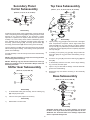
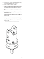
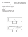
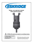
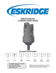
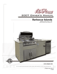
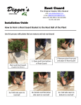
76 PLANETARY DIGGER DRIVE
SERVICE AND REPAIR MANUAL
Example Part Number
76BA
5
4
F
03
S
Series
Output
Shaft
Bail
Boss
Motor
Supplier
Motor
Number
Shift
Cylinder
THIS SERVICE MANUAL IS EFFECTIVE
FROM: ..... S/N 17050, AUG. 1993
TO:........... CURRENT
REF: ........ SM76BA
76 SERIES SERVICE MANUAL
TWO SPEED PLANETARY DIGGER DRIVES
LUBRICATION & MAINTENANCE
Change the oil after the first 50 hours of operation. Oil should be changed at 500 hour intervals thereafter. All gearboxes require a
GL-5 grade EP 80/90 gear oil for lubrication. Manufacturer also recommends that unit be partially disassembled to inspect gears and
bearings at 1000 hour intervals.
Model
Oil Capacity
Oil Level
Single Stage
6.5 pints / 3.06 liters
To horizontal centerline of primary cluster gears
Recommended ambient and operating temperatures for conventional and synthetic gear lubricants
80W90 conventional
75W90 conventional
85W140 conventional
Min Ambient/operating temp
Max Ambient temp
Max Operating temp
75W90 synthetic
80W140 synthetic
Note: Ambient temperature is the air temperature measured in the immediate vicintiy of the digger. A digger exposed to the direct rays of the
sun or other radiant heat sources will operate at higher temperatures and therefore must be given special consideration. The max operating
temperature must not be exceeded under any circumstances, regardless of ambient temperature.
Troubleshooting
Rattling, Grinding or Whining Noises
Hydraulic motor failure and/or difficulties are commonly confused with gear drive problems, as they can share similar symptoms:
reports of rattling, grinding or whining noises in the digger assembly. Carefully check the hydraulic motor for problems
before removing the digger drive from the boom. If the digger drive is removed, a motor problem can only be determined by testing
the motor on a hydraulic test stand or by eliminating the gear drive as the noise source after a total teardown of the unit.
If you determine that the hydraulic motor is the source of the problem, please contact the original equipment manufacturer of the digger
drive assembly.
Shifting Difficulties/Jumping Out of Gear
This symptom, commonly attributed to gear drive failure, can be due to air in the hydraulic lines leading to the drive, not the drive itself.
Excessive back-pressure in the system may also cause this problem.
Inability to Shift into High Gear
This symptom can be due to a poorly adjusted shift cylinder. While the cylinder is carefully set at the factory, the process of disassembly
may turn or move the cylinder in such a way that it contacts the case; contact between the cylinder body and the gear drive prevents the
rod from making its full one inch travel.
Difficult, Rough or Impossible Shifting
Hand testing a shifter may indicate a “no shift” condition even when the shifter is okay. If metal-to-metal contact is made, a short turn of
the output shaft may align shifter and allow shift to occur.
Diagnosing the Upper Gear Drive Area
The Series 76 digger drive cannot be shifted “on the fly.” The digger drive must be at a complete stop, with the load removed (backed
out of hole in ground), before shifting. Shifting on the fly is the primary cause of damage to the gears in the shifter assembly. Damage
caused by shifting on the fly will be seen as initial grinding of the gears at the gear faces, a wear pattern developing on the top of the
cluster gears and on the shift gear itself, and a severe wear pattern developing on the points of the shifter gear. Additionally, the sun
gear will show damage on the points: a rounding, or even severe burring, of these parts is possible.
2
Exploded View Drawing
76BA & 76BC
(TWO SPEED)
29
20
76BA
ITEM
QTY
1
1
71-004-0014
TOP CASE
2
1
71-004-2144
BEARING CARRIER
3
1
01-103-0080
BRG.,LOWER SHAFT CUP
4
1
71-004-0042
RING GEAR, SEC.
5
1
71-004-0142
RING GEAR, PRI.
6
1
71-004-0073
7
1
71-004-0113
8
3
71-004-0081
PLANET PIN, SEC.
9
3
71-004-0121
PLANET PIN, PRI.
76BC
DESCRIPTION
42
31
50
40
PLANET CARRIER, SEC.
71-004-0433
PLANET CARRIER, PRI.
39
43
35
22
10
3
71-004-0092
11
3
71-004-0132
12
1
71-004-0102
13
1
71-004-0172
71-004-0402
SUN GEAR, PRI.
15
1
71-004-0562
71-004-0572
SHIFTER GEAR
16
1
71-004-0772
SHIFTER COLLAR
17
6
71-004-0861
WASHER, PRI.
18
6
71-004-0871
WASHER, SEC.
19
1
71-005-0302
SHIFTER SHAFT ASSY
20
1
21
1
01-102-0100
BRG., UPPER SHAFT CONE
22
1
01-100-0040
BRG., SHIFTER
PLANET GEAR, SEC.
71-004-0412
16
CLUSTER GEAR, PRI.
SUN GEAR, SEC.
PER CUSTOMER SPEC
19
15
38
26
19
1
41
44
BAIL ASSY
28
27
23
6
01-105-0010
BRG., PRI. PLANET
24
3
01-105-0020
BRG., SEC. PLANET
25
1
01-102-0090
BRG., LOWER SHAFT CONE
26
1
01-112-0030
THRUST RACE
27
1
01-127-0010
BUSHING
28
1
71-004-0151
BUSHING
29
12
01-150-0020
CAP. SCR., 3/8-16
30
1
01-103-0090
BRG.,UPPER SHAFT CUP
31
2
01-150-0110
CAP. SCR., 5/8-11
32
8
01-150-0520
CAP. SCR., S.H., 3/8-16
33
6
01-153-0020
ROLL PIN, 3/16
34
12
01-158-0360
HEX. FLANGE NUT, 3/8-16
35
1
01-160-0100
SNAP RING, INT., NO. 268
36
1
01-160-0030
SNAP RING, EXT., NO. 255
37
1
01-160-0020
SNAP RING, EXT., NO. 237
38
1
01-160-0040
SNAP RING, EXT., NO. 250
39
1
01-160-0110
SNAP RING, EXT., NO. 156
40
2
01-166-0040
LOCKWASHER, 5/8
41
2
01-207-0010
13
47
17
33
5
23
11
32
17
7
9
36
4
12
37
44
33
18
24
6
10
PIPE PLUG, 1/2 NPT
SHIFT CYLINDER ASSEMBLIES
42
1
71-002-0601
SINGLE ACTING (STD) HYD.
71-002-1351
SINGLE ACT. HEAVY DUTY HYD
71-002-0692
DOUBLE ACTING HYD.
71-002-0322
AIR
71-002-1542
VACUUM
43
1
01-402-0010
O-RING, NO. 250
44
2
01-402-0020
O-RING, NO. 276
46
1
01-405-0540
OIL SEAL
47
2
49
1
50
1
18
21
8
30
2
34
41
3
01-152-0070
DOWEL PIN
71-004-0513
2-1/2" HEX. OUTPUT SHAFT
71-004-1383
2-5/8" HEX. OUTPUT SHAFT
PER CUSTOMER SPEC
HYDRAULIC MOTOR
25
49
OPTIONS
SEAL KIT P/N 76-016-2011
INCLUDES ITEMS 43,44,46 AND
O-RING FOR SHIFTER SHAFT ASSEMBLY.
E.C.N. 1803
X76-AB
DATE: 5-02-06
46
3
15)
Unit Disassembly Procedure
(Refer to Exploded View Drawing on Page 3)
1)
2)
NOTE: See Service Bulletin #013 concerning the wear of secondary planet carriers.
Scribe from bail assembly (20) to the bearing carrier (2),
across the outside of the digger drive to assure proper orientation of oil fill and drain plugs, motor mounting, etc., as the
unit is reassembled.
The unit is now disassembled into groups of parts and/or
subassemblies. The area(s) requiring repair or service should
be identified by thorough inspection of the parts after they
have been washed in solvent.
To drain oil, position unit on its side and remove oil plug (41)
located in the top case (1). To help ventilate oil while draining,
loosen hydraulic motor bolts (31). Maximum drainage occurs
when oil is warm.
Primary Planet
Carrier Subassembly
NOTE: Particular care should be taken when placing the unit
in a position for servicing. Unit should be blocked up so that
weight of the unit is resting on the bearing carrier (2). This
fixture must be secure so that the auger drive will not tip over
during disassembly and assembly procedures.
3)
4)
5)
6)
Lift the secondary planet carrier subassembly out of the unit
(includes Items 6, 8, 10 ,18, 24 & 33); use a puller, if needed.
(Items 7, 9, 11, 17, 23 & 33)
17
33
23
Loosen upper shift cylinder bolt (part of Item 42);
note location and remove.
11
If shifter performance is in doubt, leave lower bolt in place
and follow cylinder adjustment procedure (Step 19 in Unit
Assembly Procedure) to see if poor cylinder adjustment could
be the cause of “no shift” or “partial shift” condition.
17
7
9
Note location of lower washer. Remove lower shift
cylinder (42), bolt, nut and washer; bolt and nut are
accessible through the bail.
Disassembly
Rotate cluster gears (11) to check for any abnormal noises or
roughness in the primary planet bearings (23) or planet shafts (9). If
replacement or further inspection is required, proceed as follows.
Remove twelve hex head capscrews (29) and hex flange nuts
(34) from bail assembly (20); lift bail from unit.
NOTE: There are no bolts retaining the major components
together; proceed with caution when moving the unit.
1)
Drive the roll pins (30) completely into the planet shafts (9).
2)
Press planet shafts out of carrier (6).
7)
Remove two capscrews (31) and lock washers (40) from
hydraulic motor (50). Notice that the motor is larger on one
side: it must be replaced the same position as removed.
Remove motor from unit. Check o-ring (43) for damage.
3)
Remove cluster gears (11) and primary planet washers (17)
from carrier (6). The cluster gears are a matched set and all
three should be replaced if damaged.
4)
8)
Observe location of shift fork (part of Item 19), shifter gear
assembly (Items 15, 16, 22, 35 & 39) and top case (1). Check
for binding or loose shift connections.
If any of the primary planet bearings (23) need replacing,
press them out of planet gears (11); replace with new bearings.
5)
9)
Press down on shift lever (part of Item 19). Remove shifter gear assembly (Items 15, 16, 22, 35 & 39). If shifter is
jammed in sun gear (13) and cannot be removed, dismantle
shifter assembly in the case by removing snap rings (35 &
38) and pulling bearing (22) and collar (16) out of fork. Shifter
gear (15) should be free of nicks, burrs or gouges.
Check primary planet shafts (9) for any abnormal wear,
especially ones in which bearings needed to be replaced.
If any abnormal wear is found, replace planet shaft.
6)
Using a punch, drive roll pins (33) out of planet shafts (9).
7)
With a primary planet washer (17) on both sides of cluster
gear (11) and with bearings (23) installed, slide gear into carrier (7) and insert primary planet shaft (9) through carrier,
planet gear and washers.
8)
Planet shafts (9) should be installed with chamfered end of
1/8 inch hole toward outside diameter of the carrier (7). This
will aid in alignment of holes while inserting roll pins (33).
9)
Drive three roll pins (33) through the carrier holes and into the
planet shafts to retain the parts.
10)
Use a screwdriver, wood chisel or similar flat strong tool
ground flat for insertion between the aluminum top case (1)
and the ring gear (4). Tap lightly on tool: do not drive into
case, heavy prying will damage the o-ring contact surfaces in
the case. Remove the top case assembly (includes Items 1,
5, 13, 19, 26, 27, 28, 32, 38, 41 & 47).
11)
Lift the primary planet carrier subassembly out of the unit (includes Items 7, 9, 11, 17, 23 & 33).
12)
If sun gear (12) has not been removed from digger drive, do
so now. (Sometimes the sun gear sticks to the primary carrier
(7).)
13)
Remove secondary ring gear (4).
14)
Remove retaining ring (37) from end of output shaft (49).
CAUTION: Output shaft is not retained at this point.
4
Top Case Subassembly
Secondary Planet
Carrier Subassembly
(Items 1, 5, 13, 19, 26, 27, 28, 32, 38, 41 & 47)
19
(Items 6, 8, 10, 18, 21, 24, 33 & 37)
38
33
18
26
24
6
19
1
10
41
18
44
8
28
27
Disassembly
13
47
As with the primary planet carrier subassembly, check for abnormal
noise in the planet gear bearings (24) by rotating the planets while
listening for any noise and feeling for any roughness. If further
inspection or replacement is required, follow the same procedure
as Steps 1-6 of the Primary Planet Carrier Subassembly Procedure. Substitute items as indicated: secondary planet gears (10),
secondary planet bearings (24), secondary planet shafts (8),
secondary planet washers (18) and secondary planet carrier (6).
5
Disassembly
32
1)
Inspect primary ring gear (5) for abnormal wear or damaged
teeth. If replacement if required, remove eight socket head
capscrews (32) from ring gear. Primary ring (5) is doweled
into top case (1); use puller holes provided to thread two 3/816 bolts into ring gear (5) until part was completely separated
from top case (1).
2)
If installing a new primary ring gear (5), always install new
dowel pins (47) into ring gear before reassembling into top
case (1).
NOTE 1: See Service Bulletin on Page 10 concerning the wear
of secondary planet carriers (6).
3)
To remove sun gear (13), first remove retaining ring (38) and
shim (26).
NOTE 2: Retaining ring (37) must be inserted into carrier (6)
before it is installed in unit, as described in Step 2 of the Unit
Assembly Procedure.
4)
To disassembly shift lever and fork, remove large retaining
ring on inside, then slide apart.
Shifter Gear Subassembly
5)
Inspect o-ring on shift shaft for damage. Lubricate shaft with
grease when reassembling.
6)
Reassemble top case before continuing to Unit Assembly
Procedure.
The inner bearing cone (21) cannot be removed from the carrier (6)
without destroying the bearing. If the bearing needs replacement,
please consult Eskridge.
Proceed with Steps 7-9 of the Primary Planet Carrier Subassembly
Procedure.
(Items 15, 16, 22, 35 & 39)
39
35
Base Subassembly
22
16
(Items 2, 3, 25, 30, 41, 46 & 49)
15
30
2
34
Disassembly
41
1)
To disassemble shifter gear assembly, remove retaining ring
(39) and pull pieces apart.
2)
Check for worn parts; replace as necessary.
3
25
49
Reassembly
1)
Reassemble in reverse order.
46
Disassembly
CAUTION: Output shaft is no longer retained; care should
be taken not to injure feet because output shaft can fall out.
Additional care should be taken not to damage output shaft
when it is pressed through base.
5
1)
Output shaft removal:
carrier (6).
Bearing carrier (2) should be set pinion side down, as shown,
on a plate or table with output shaft (49) protruding through
a hole in the table. Press output shaft out bottom of base by
applying a load to top end (internal end) of shaft until it passes through inner shaft bearing cone (21).
4)
Install the secondary planet carrier (6) assembly by rotating
it until carrier spline lines up with shaft spline. Begin pressing
carrier onto shaft.
5)
Before secondary carrier is fully seated, install retaining ring
(37) onto end of output shaft.
NOTE: If reusing old bearing cone, do not damage roller cage
by pulling on it.
6)
Continue pressing secondary carrier until fully seated.
Check retaining ring (37) to be sure it is in the ring groove.
7)
Install a new o-ring (44) on the bearing carrier (2).
8)
Check to be sure retaining ring (36) is installed on sun gear
(12). Slide the sun gear into the secondary planet carrier.
9)
Install the primary carrier (7) by rotating until spline lines up
with sun gear; assembly should drop into place.
10)
Install a new o-ring (44) on top case (1); use grease to help
hold it in place.
2)
If outer bearing cone (25) needs to be replaced, a gear puller
may be used to remove it from output shaft (49).
3)
Remove the shaft seal (46) for inspection or replacement.
Lubricate inner lip of new shaft seal (46) and slide the seal
onto the shaft (49) until it fits snugly over shaft seal diameter
with the open side toward the inside of the digger drive.
Reassembly
NOTE: Press bearing cone onto output shaft by pressing on
inner race only. Do not press on roller cage, or it may damage
bearing.
1)
Press outer bearing cone (25, large end down as shown)
onto the shaft until it seats against the shoulder. Bearing cone
(25) may be reused if it was removed only to replace the seal
(46).
2)
Clean all foreign material from magnetic oil plug (41). Add a
small amount of pipe thread compound to pipe plug before
installing back into bearing carrier (2).
3)
Place the bearing carrier (2, output side up, opposite
shown in diagram) on the press table.
4)
Apply a layer of lithium or general purpose bearing grease
to surface of outer bearing cup (3). Insert the shaft (49) into
the bearing carrier (2, bearing cone down) and use a soft
hammer to install the shaft seal (46) into the bearing carrier.
CAUTION: Output shaft is not retained at this point.
5)
Invert this assembly on the press table, so it is standing on
the shaft.
All subassembly service or repairs should complete at this
point. Continue to Unit Assembly Procedure to complete unit
buildup.
11)
Unit Reassembly
There are machinist’s marks on each of the three cluster
gears (11). These marks should be aligned so that each
points toward the center of the primary planet carrier.
See Timing Procedure Diagram.
(Refer to Exploded Drawing on Page 3)
A special tool should be made for the timing process. An old
timing gear, cut off above the lower gear and welded to a 6” long
bolt, works well. If an extra timing gear is not available, the timing
will be more difficult; the timing tool keeps gears in time as they
mesh with primary ring gear (5) (mounted in top case (1)).
1)
Use the of the timing tools mentioned above will make
top case installation easier. Leave the timing tool in the
center of the cluster gears and use it to rotate them until
top case is properly installed.
When all subassemblies at complete, the unit is ready to be
assembled. Place lower assembly back on blocks, which
were used during the initial unit disassembly procedures, for
remaining unit build up.
While keeping the timing marks aligned, position the top
case (1) near the proper orientation to scribed line on
outside of unit. Work top case down until fully seated
with gears in time.
CAUTION: Output shaft is not retained.
2)
Install a new o-ring (44) on the bearing carrier (2). Referring
to scribe marks for proper orientation, install the secondary
ring gear (4).
3)
Push retaining ring (37) into center of secondary planet
Timing Procedure:
CAUTION: If unit is not properly timed, the gear drive
will be severely damaged. Be sure gear drive turns
smoothly and easily.
12)
6
Fill unit with EP 80/90 gear oil to proper level as specified on
Page 2.
13)
Install shifter gear assembly (15, 16, 22, 35 & 39) by lifting
shift lever (part of Item 19) to allow clearance.
14)
Install o-ring (43) onto hydraulic motor (50).
15)
Using hand tools to avoid stripping the aluminum, install
hydraulic motor (50) on mounting pad on top case (1) with two
capscrews (31) and lockwashers (40); torque to 130 ft-lbs.
16)
Bolt lower end of shift cylinder assembly (42) to shift lever
(19).
17)
Line up scribe mark on bail assembly (20) with scribe mark on
top case (1) and lower bail over hydraulic motor (50) until bail
flange contacts the cover.
18)
Check all o-rings to make sure they are properly seated.
Install twelve capscrews (29) with hex flange nuts (34) and
torque to 30 ft-lbs.
19)
Install and adjust shifter:
Shifter cylinder should be compressed to its shortest length.
Next, with the shifter gear pushed all the way up (bail side),
adjust the length of the shifter cylinder to allow installation;
torque to 70 ft-lbs.
THE DIGGER DRIVE IS NOW READY FOR USE.
7
Service Division Bulletin #013
Eskridge Series 76 and 77 Digger Drives
Revision 1 supersedes bulletin dated 01/14/86
Fill gear drive with EP 80/90 gear oil until it runs out of the fill plug
while the digger drive is leaning approximately 3½” from vertical
(about 7°). A dry gear drive will hold about 6½ pints of oil in this
condition.
Date: 06/01/87
Reference: All Series 71/76, 72/77 and 73/78 Digger Drives
Subject: Inspection of Secondary Carriers
When repairing, updating or inspecting an auger drive, the secondary carrier should be inspected for possible wear around the spline
where it contacts the shaft retaining ring. Under heavy use and/or
in rocky regions, continual impacting of the retaining ring against
the carrier may cause wear in this area. If it wears to a beveled
shaped, high loading in the pull out direction could cause the shaft
retaining ring to dislodge from its groove allowing the hex shaft to
pull out of the unit.
If the carrier is found to be worn to a bevel shape when inspected,
it should be replaced with carrier part number 71-004-0073. Units
with serial numbers prior to 4900 should also have the hex output
shaft replaced with the current production revision, part number
71-004-0513.
8