1
OPERATING
AND
SERVICE
LAB BENCH DC POWER SUPPLIES
HP E361XA 60W SERIES
.
~;
Flio- HEWLETT®
~e.II PACKARD
e.
4.
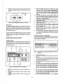
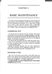
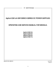
DISPLAY OVP/CC SET Switch: Pressing this swltoh
oauses the VOLTS display to show voltage 'setting for
overvoltage shutdown (trip voltage) and'theAMPS display
to show the current control set value. Setting valu~s are
either front panel settings or remote ''voltage programmed
settings.
5.
OVP Adjust Screwdriver Control: While pressing the
DISPLAY OVP/CC SET switch. rotstlng the conlrol clockwise with a small, flat-blade screwdnver.jncreeeee. the
setting for overvoltageshutdown.
6.
VOL1:S Disp!ay: Digital dleplev of,aotual output voltage, or
OVP shutdown setting.
7.
AMPS Display: Digital display of actual output current, or
output-current setting.
S.
CV'" LED "Indicator: Output voltage is regulated when
lighted. This means the power supply is operating in the
constant voltage mode.
9.
CC LED Indicator: Output current is regulated, when
lighted. This means the power supply is operating in the
constant current mode.
10. OVP LED Indicator: Output is shutdown by the occurrence
of an overvoltage when lighted. Removing the cause of
overvoltage and turning the power off, then on, resets the
power supply.
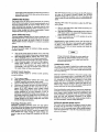
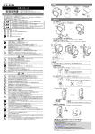
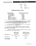
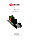
Replaoe the cover 'and mark the supply olearly with a tag
or lebel indioating the correct line voltage and fuse that is .
in use.
Figure 2. Line Voltage Selector (set for 115 Va c)
Power Cord
To protect operating personnel, the Instrument should be
grounded. This instrument is equipped with a three conduotor
power cord, The third conductor is the ground conductor and
when the power oord is plugged into an appropriate receptacle,
the supply is grounded.
The power supply was shipped with a power cord for the type
of outlet used at your location. If the appropriate cord was not
included, contact your nearest HP Sales Office to obtain the
correot oord.
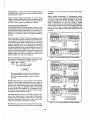
TURN-ON CHECKOUT PROCEDURE
The following checkout prooedure describes the use of the front
panel controls and indicators-illustrated in Figure 3 and ensures
that the supply is operational:
OPERATING INSTRUCTIONS
INTRODUCTION
This section explains the operating controls and indicators and
provides information on many operating modes possible with
your instrument. The front panel controls and indicators are
, illustrated In Figure 3.
r- .....T VI.-,r--
~
~~~~ ~,,",
_I
«
-
= = =
() () ()
•
e
*
•
-
c
"
()()()() oe() ~b
o
~
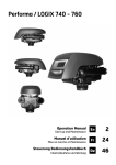
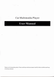
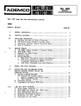
Figure 4. Switch Settings of Bear-Panel Control for Turn-On
Checkout
s.
-
-,....
b.
.
-
-
"'
o.
000
:t ...
nc ... TO.1
d.
e.
5
10
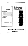
f.
Figure 3. Front-Panel Controls and Indicators
-
1.
2.
3.
<;;
Disconneot power cord.
Check that the rear-pane! switch settings are as shown In
Figute 4.
.
Check that the rear panel label indicates that the supply is
set to match your input line voltage (If not, refer to "Line
Voltage Option Conversion" .I.
Cheokthat the fuse onthe rear panells correot for your
line voltage.
Connect the power cord and push the LINE switch to ON.
While pressing OVP/CC SET switoh,verify that the OVP
shutdown is set above 8.0, 20.0, 3'5.0, or 60.0 Vdo for
E3614A, E3615A, E3616A, or E3617A reepecttvelv. If
not, turn up OVP Adjust wlthe small flat-blade ecrewdrlv-
er.
LINE Switch: Pressing this switoh turns the supply on, or
g.
•
off.
VOLTAGE Control: Clockwise rotation increases output
voltage.
CURRENT Control: Clockwise rotation increases output
current.
h.
1-7
Turn VOLTAGE control fully counter olookwiseto ensure
that the 'output of VOLTS display decreases to OVdo,
then fully clockwise to ensure that output voltage lncreases to the maximum output voltage.
While pressing OVP/CC SeT switch, turn the CURRENT
.control fullv.counter.clcckwlse and then fUlly clockwise to
;oens.uretpaUheourrent llrnltvalue can be set from zero to
False OVP shutdowns may occur Ifyou set the OVP shutdown
to·oolOje -tc .the. supply's operating voltage. Set the OVP
shutdown voltage 4% of output + 2.0 V or more above the
output voltage to avoid false shutdowns from load-Induced transients.
'. .rnaximum rated-value.
OPERATING MODES
The settin" of ~h8rear panel switch determines the operating
modes ctthe power supplyiThe'localoperatingmode is set so
the'power'supply-'senses the-output -vclteqe directly 'at the
output-terminals {Ioo-al sensing) for operation using the front
panel c.onuo',s. (Io.cal prog,rammhig). Oth~r operating modes are:
remote :voltage: sensing -and remote programming of output
voltage and current using external voltagas.
Adjusting OVP. Follow this procedure to adjust the OVP shutdown voltage.
a. With the VOLTAGE control fUlly counter clockwise, turn
on the power supply.
'b. Whiledepressing DISPLAYOVP/CC SETswitch, adjust the
OVP Adjust controlto the desired OVP shutdown using 8
small, flat-blade screwdriver.
o. Follow the procedure for CC or CV operation to set the
output voltage and current.
LOCAL OPERATING MODE
ThepoWersupplylsshlppedfrom the tacrcrv configured in the
local operatihgmode.-local operating mode requires the switch
stltting~ ~ftherefl' panel, as shownin,Figure 4. The power
supplr p.rovides constant -voltage(CV) orconstentounenttccj
Resetting OvP. If OVP shutdown occurs, reset the supply by
turning power o~f.Waitone;ormore eeccnde, and turn power
on again. IfOVP shutdown continue to occur, check the
connections to the load and sense terminals. and check the
OVP limit setting.
output. '
Constant Voltage Operation
~os,e,tup;'a,.JJ'~\Ne,-
supply for constant voltage operation,
proceed 'as' follows:
a.
b.
c.
d.
NOTE
Turn on the pow~:~"suppl'l.~nd adjust, lO-turnVOlT"GE
c5m~ro.1 f.ordesir~:d output voltage (output terminals open).
WhU~.'~,epressing plSPlAY -OVP/CC SET switch, adjust
10-turn'CURRENTcontrol for the desired current limit.
With po"".,roff connect the load to the OUtput terminals.
Tum9r)ttl~ 1'9V'(~rsupply. Verifythat CVLEo.lslighted.
During actual operation, if a load change causes the
current limit to be exceeded, the power supply will
automatically erose over to constant current mode and
the output voltage will drop proportionately.
Strong electrostatic discharge to power SUP~/ycan
make OVP trip andev~ntually crowbar the output
Which can effectively protect OlJtp'ut loads from th;
hazardous ESD current.
CONNECTING LOADS
The output of the supply Is isolated from earth ground. Either
output terminal may be grounded or-the output can be floated
up to 240 volts off ground. Total output voltage to ground must
not exceed 240 Vdc.
Constant Current Operetion
To set up a power supply for constant current operation,
proceed as follows;
Each load should be connected to the power supply output
terminals using separate pairs of connecting wires. This will
minimize mutualoouplingeffects between loads and will retain
full advantage of the low output impedance of the power
supply. Each pair of. connecting wires .ehould be . as . short. as
possible and twlsted cr ehlelded tc reduce nclee.pfck-up. (If a
shield is used, connect one end to' the power supply ground
terminal and leave the otherend uncorinected.I
Turnon-po.~er.suppIY..
'
While·depressing ·oISPLAY OVP/CC·SET SWitch. adjust
CU~RENT control-for the desired output current.
o. Turn up the 'VOLTAG Econtrol to the desired voltage limit.
d. Wit~,poweroff connect~hel,Oad to the output terminal.
a. Turn on power supply a-nd then verify that CC LED is
IIght~d. (If CV. LED is Iightad, choose • hlgher voltage
limit~.~ .v~lta~e' . setting t~at is greater than the current
setting multiplied by the load resistance in ohms is
re.qyired,for..~.C: . 0perat~on~).During'aotual'oP'eration. if a
loadcharige"oauses thevcltejje limit to be exceeded. the
pow.ar:~u~~ly . \N1118.U~OJ~:'~tica.IlY cross over to constant
, v~ltag'e. ~~.erat.l~n '~t~hepresat voltaue limit end output
,c,urrerlt will ~r?~ proportionately..
a.
b.
If load considerations require that the output power distribution
terminals be remotel.ylocated from the power supply, then the
power supply output terminals should be connected to the
remote distribution termlnels vla a pair of twisted or shielded
wires and each load separately connected to the remote
distribution terminals. For this case, remote sensing should be
used (See paragraph "Remote Voltage Sensing").
OPERATlON.~EYOND RATED OUTPUT
The output controls can adjust the voltage or current to values
up to 5% over the rated output. Although the supply can be
operated in the 5% overrange region without being damaged,
it can not be guaranteed to meet all of its performance speclfications in this region.
O\rer\rOlta!lePi~t~qilon(OVPI
Adjustable overvoltage proteotlon 'guards· your ··Ioad against
o:v~rV?ltllg.tJ. W~e~~h~ :~~Itllg~ .at the output terminals increases
(l)rhfl~~re~.$t)d~Y,8n~><t~:,~arsource) to the OVP shutdown
VO.~t8g,~ ~~,s.et by th~~qYr~A~JYS!~ontrol~thesupply'sOVP
olrcult "disables the o~tPllt.oauslng. the.outp'utvoltage and
cL!,rre~ntto .~r()P.t() zero.-Ouring OVPshutdown:the OVP LED
lights.··
'.
1-8
REMOTE OPERATING MODES
Output Noise. Any noise picked up on the sense lel'ids will
appear at the supply's output voltage and may degrade CV lcsd
regulation. Twist the sense leads to -minimize the plckup of
external noise and run them parallel and close to the load leads.
In nclsv envlronments, it mev be:nec-~ssaiy:toshielcf the"sense
"leads. Ground the shield at the-pow~rsuppIY end only, Do not
use the shield as one of the sensingoonductors.
-aemote operating modes-discussed below are remote voltage
sensing and remote voltage programming. You can set up the
uniHor remote operating modes by changing the settings of the
rear panel switch and conneotlng the leads from the rear panel
terminals to the load or the external voltage. Solid conductors
of 0;75 to 1.5 mm 2 cen be connected to the rear panel termlnals by simply push fitting. -Thinner wires or conductors -are
inserted into the connection space after depressing the orange
Stability. When the supply le conriected fer remote sensing, it
is possible for the impedance of the load wires and the oapaci·
tance of the load to form 8 filter, which \viii become part of the
supply's CV feedback loop. The' extrs·phaseshlft created by
this filter can degrade the sypply's stability and oan result In
poor transient response performanc61<'or"loop stability. In
extreme cases, it can cause oscillations; Keep the leads 08
short as possible and twist the leads of the load to eliminate the
load lead Inductance and keep the load capacitance 8S small as
possible.The load leads "should be "of,the-'Iargest . . diameter
practical, heavy enough to limit the voltage drop in eaoh lead to
0.5 volts.
cpenlnq'Iever.
IC~UTION I
Turn off the supply while making changes to rear
panel switch settings or connections. This avoids the
possibility of damage to the load and OVP shutdown
from unintended output.
Remote Voltage Sensing
Remote voltage sensing is used to maintain good regulation at
the load and reduce the degradation of regulation that would
occur.due to the voltage drop in the leads between the power
supply and the load. By connecting the supply for remote
voltage sensing, voltage is sensed at the load rather than at the
supply's output terminals. This will allow the supply to automaticallycompensate for the voltage drop in the load leads and
improve regulation.
The sense-leads are part of the supply'S programming feedbaok
control loop. Aocidental open-connections of sense or load
leads during remote sensing operation have various unwented
effects. Provide secure, permanent conneotlone-especlellv for
the sense leads.
rIAASTEII..,r-- LQC,I,l---,
~ ~~ ~
When the supply is connected for remote sensing, the OVP
circuit senses the voltage at the sense leads and not the main
output termlnele.
•
""" .,
NOTE
M~t WS2
tv
cc
l - stAVlS-JL...-./WklTE---J
Remote voltage sensing compensates for a voltage
drop of up to 0.5 V in each load, and there may be
up to a O. 1 V drop between the output terminal and
the internal sensing resistor, at which point the OVP
circuit is connected. Therefore, the voltage sensed
by/he OVP circuit could be 8S much as 1.1 V more
tha" the voltage being regulated at the load. It may
be necessary to re-adjust the OVP trip voltage when
using remote sensing.
-
.
LOAO
-
-II\-
-
+ - + -
== =
t\ jJ 19 (J(J(J(J(J (J(J(J(J(J
•
CY
co \'llU Al n
A3 M M
f)
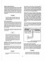
NOTE: Twist sense leads andload leads I
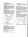
Figure 5. Remote Voltage
CV.Regulation. Notice that any voltage drop in the senseleads
adds directly to the CV load regulation. In order to maintain the
specified performance, keep the sense lead resistance to 0.5
ohms per lead or less.
Se~lng
.
Remote Analog Voltage Programming
Remote analog voltage programming permits control of the
regulated output voltage or current by means of 8 remotely
varied voltage. The programming (external) voltage should not
exceed 10 volts. The stability of the programming voltages
directly affects the stability of the output. The voltage oontrol
on the front panel is disabled during remote analog programmingo
Remote Sensing Connections. Remote sensing requires changIng settings of the rear panel switch and connecting the load
leads from + and ~ output terminals to the load and connecting
the sense leads from the + Sand -S terminals to the load as
shown in Figure 5.
f;
ICAUTION I
The supply includes clamp circuits to prevent it from
supplying more than about 120% of reted output
voltage or current when the remote programming
Observe polarity when connecting the sensing leads
to the load.
1·9
"-Q/tagel$,greater than 1-() Vdc. Do not intentionally
op-erat~th8,suppiy SbPV8 .100% reted output. Limit
¥()t/f p(pg;smming va/tagB to 10 Vdc.
MULTIPLE-SUPPLY OPERATION
NormTII parallel and auto-parallel operation provides Increased
output current while normal. series and auto-aetlee provides
increased output voltage. Auto-tracking provides single control
of output voltage of more than one supply. You can aet up the
unit for multlple-supplv operation by changing the settings of
the -rear panel switch and uonnectlnathe leeds from the rear
panelterminals to the load. Solid conductors of 0.75 to 1.5
mm" can be 'connected to the rear panel terminals by simply
push fitting. Thinner wires of conductors are inserted into the
<connection space after depressing the orange opening lever.
Re';'ot~,Progr.Rtmlng.'.ConnectJQn~. Remote programming
reqUire8",chaf1gin1l8e~tlrlg8,.of .the switch and, conneetlnq
external voltag(ls:~o_+ end- terminals of "CV" or"CC"on the
rear panel. Any nciae.plcked up on the-programming leads will
appear on ~h,esupply's o~tput and may degrade regulation. To
redu(l:e noise pick-up, use a twisted or shielded pair of wires for
prograrnml.ng,.wlththe shield grounded at one end only. Do not
use the shield _8S a.ccnductcr.
NORMAL PARALLEL OPERATION
Notice that it'is .poselble to operate a power supply slmultenecuslv lnthe remote senslnq and the remote analog programming modes.
Two or more power supplies being capable of CV(CCautomatic
cross over operetlon can be connected In parallel to obtain a
total output ourrent greater than that available trom one power
supply. The total output current is the sum "of the .output
currents of the individual power supplies. The output of each
power supply can be set separately. The output voltage
controls of one power supply should be sat ··to .the desired
outputvoltegs; the other power supply should be sst for a
slightly higher output voltage. The supply with the higher
output voltage setting will deliver its oonstant currant output,
and drop its output voltage until hequals the output of the
other supply,and.,the other supply wltl femalnIn constant
voltage operation and .only deliver that fraction of its rated
output.current which is necessary to fulfill the vtctat.Iead
demand. Figure 8 shows ths rear panel switch settings and
terminal connections for normal parallel operation of two
supplies.
Remot.,Program01lng."Consts.nt Voltage. Figure 6 shows the
rear penelawltch sett.ings and .termlnel connections for remote~0lt8ge control of output voltage. A 1 Vdc change in the remote
programming voltage produces a change in output
volt~geJyoltegegeln)esfollows:E3614A: 0.8 Vdo, E3615A:
2 Vdo, E~616A:3.5Vdo, E3517A: 6 Vdo
r- ~":;r---- -....
~
"~~ - ..
..
..... ,""I
~
~
- , -
= = -=
,
0 0 0 0
"
l - iIJi'W....J~'....m.---'
"'""
$e$1toe~t.Ianu8l,lf)'OUarerd.U$IrIg
~~~-.
~
•
000000 00
~
cc _
.... }.2
....
AI ....
L,,~
r-r-
~
~
~ ~~ ~
Figure 6. Remote'Voltage Programming, Constant Voltage
IoWI 1oW2
W
CC
,
0
-
l.-- etA.".~t-.--REYOt'£-----'
Remote Program-mlng, Constant Current. Figure 7 shows the
rear panel switch settings and terminal connections for remotevoltage control of output current. A fVdc change in the remote
programming voltage produces a change in output current
(current geln) ee follows: E3614A: 0.6 Ado, E3615A: 0.3 Ado,
E3616A:0.17 Ado. E3617A:0.l Ado
r--_-,~-....
~
~ ~~ ~
..... "'I
l - ...-
~
.
cc
....JL...-....;....
... _
IO&DT!- - - '
= =
=
-
=
"'St
-
0 0 0 0
~
•
CI
CC
0
I ro
-e
fw
lOAD
.
0
=
0
,-
~
~
00000 00000
r.:'I
+ -
OOWEfA1UJoJMn
• -
MOM 00000
I
eeee
.$
QVT
-e
W
00 WEfAl J,:J;J>:l M M
Figure a.Normal Parallel Operation 01 Two Supplies .
8
AUTO·PARALLEL OPERATION
~
O;':..- ....
Q n " ' ....
Auto-parallel operation permits equal current sharing under all
load oonditlons, and allows complete 'control of output current
from one-master supply. The 'control unit is called the mesten
the controlled units are called, elevea.: Normally; only supplies
having the same model number shouldbe oonneoted tor. autoparallel operation, since the supplies must have the same
voltage drop across the current monitoring resistor at full
current fating. The output current of each slave Is approximately equal to the master's. Fig'ure 9 and Figure 10 show the rear
panel switch settings and terminal connections for auto-parallel
operation of two supplies and three supplies.
"'"" .
~Vl$~l1¥Ulf.lf)'OUarenotlMh,)
~~'odlIgs1OlA'Ce.
_2
=
l.-- etAV£~L...--REYOTE-----'
dl600 000
.,
.,
" " " " SQl'Ply
r-:'"~,..---....lOCI\I..,........,....
~ ~~ ~
-
== ==
L;'I
Figure 7. Remote Voltage.·Prog.rammlng, Constant Current
Remote Progrllmmlng Speed. See the table of Specjflcetlona,
pege 1·5.
1-10
programming according to the remote·programming instructions.
Setting Voltage and Current. Turn the. slave unit's CURRENT
oontrol fully clockwise. Adjust the master unit's controls to set
the desired output voltage and current. The master supply
operates in a completely normal fashion and may be set up for
either constant voltage or constant current operation as
required. Verify that the slave Is in'CV operation.
lMSTERI'OWeRSUPPLY
For auto-parallel operation of two supplies, the combined output
voltage is the same as the master unit's voltage setting, endthe
ccmblned output current Is two times the master unit's current.
In general, for two supplies, the euto-parallel output current(lo)
10
10= 1m
+
where
~~~~ ~
""""COI
Proportional currents from auto-paralleled units
require equet toed-leed voltage drops. Connect each
supply to the load using separate pairs of wire with
length chosen to provide equal voltage drops from
pair to pair. If this is not feasible, connect each
supply to a pair of distribution terminalsusing equstvoltage-drop wire pairs, and then connect the distri·
bution terminals to the load with a single pair of
leads.
-
()()()()
LOAD
SlAVE POWER$UPPlY
r-lWIrol-,r---- locAl.--,
=
),1.'$' WU
~
ec
SfHSE' S
'-- SlJIYE"....Jl..--RalOfE--I
()
()()()()() ()()
=
•
tv
w
...... UH
~-
0::
+ - ... -
=
0
_.,
0
00000
•
~
w
00
...... UH
~-
NORMAL SERIES OPERATION
Series operation of two or more power supplies can be 'accomplished up to the output isolation rating of anyone supply-to
obtain a higher voltage than that available from a single supply.
Series connected supplies can be operated with one load ecrcee
both supplies or with a separate load for each supply. These
power supplies have a reverse polarity diode oonnected ecrcae
the output terminals so that if operated In series with other
supplies, damage will not occur if the load is ehort-clroulted or
if one supply is turned on separately from its series partners.
When this connection Is used. the output voltage is the sum of
the voltages of the individual supplies. Each of the Individual
supplies must be adjusted In order to obtain the total output
voltage. Figure 11 shows the rear panel switch settings and
terminal connections for normal series operation of two supplies.
..
~ ~ ~~ ~
0000 !)O 0
Figure 10. Auto-Parallel Operation of Three Supplies
-
()()()()()
0
'''''
'-0U>tI...lL....-_ff----'
..
+-+-
SlAVEPO'MRSUPPLY
,-w.owo-tr-- l.OCo'<.---,
NOTE
MASTER POWER SUF'!'lY
-
=
•
15= 21m
1m= master unit's output current
Is = slave unit's output current
o
•
~"'r-- loe.ol.---,
()()
CC~"''''A3M.u
Figure 9. Auto·Parallel Operation of Two Supplies
~
~~~~ ~
Overvoltage Protection. Adjust the desired OVPShutdown limit
using the master unit's OVPAdjust control. Set the slave units'
OVPHmlts-above the master's. When a master-unit shuts down.
the master programs the slave units to zero voltage output. If
a slave unit shuts down, It shuts only itself down. If the
required current is great enough. the master will switch from ~
CV to CC operation.
.
-
== ==
o
o
~ll~:'~~~~.s
.()()
10IJl
•
cy
-
~
ceo~O e () ()
ee
W:EFA' kl
n
M M
LOAD
P(l'M.Rst.lPPLY
r-~r-
LOCAl--,
.
=
~ ~~ ~. ..
e
Remote Sensing. To remote sense with auto·parallel cperatlcn,
connect remote-sense leads only to the master unit according
to the remote-sensing instructions.
1.\$1
Remote Analog Voltage Programming. To remote program with
auto-parallel operation, set up only the master unit for remote
M1l2
~
cc
=
. - .-
-
() ()
()()()()()
()()(j()()
seee
Figure 11. Normal Series Operation of Two Supplies
,
HI
AUTO·SERIES OPERATION
RENT control' of slave unit above "the master unit's currant
setting to avoid having the slave switch to CC operation.
Auto-serles operation permits equal or proportional voltage
sharing,. and allows control of output voltage from one master
unit. Ths"voltag's of the slaves is determlnedbv the setting of
the front pene! VOLTAGE oontrol on the master-end voltage
divider reslst()r.Themsstar unlt must be the most positive
supply of the serle'a.The output CURRENTcontrols of all series
units era operative and the current limit is equal to the lowest
setting. If any output -'CURRENT"controisare set, too low,
automatio or08S over to constant current operation will occur
and the output voltage will drop. Figure 12 and Figure 13 show
the rear panel, switoh settings and terminalconneotions for
Auto-series operation of two supplies and three supplies, This
mode can also give ±voltage tracking operation of two supplies
with two separate loads,
l \
When in CC operation the combined output ourrent is the same
as the master unit's current -setting; and when in CV operation
the combined output voltage Is the sum of the master unit's and
the slave unit's output voltages.
Ov~rv.olt8ge Proteotion. Set the OVPshutdown voltage in each
unit so that it shuts down at a voltage higher than its output
voltage during auto-series operation. When a master unit shuts
down, it programs any slave units to zero output. When a slave
unit shuts down, it shuts down onlv itself (and any slaves
below It in the stack). The master (and all slaves above the
shut-down slave) continues to supply output voltage.
Mixed model "numbers may be employed In auto-series combination without restriotion, provided that each slave is specified
as being capable of auto-aerles operetlcn. If the master supply
is set up for constant current operation, then the master-slave
combination will act 8S 8 composite constant current source.
~
~ ~~ ~
""j
ICAUTION
~
I
L..,-
Totlil qiJlP.()t·Y9!tagt/."lo grouiJ,imust not exceed 240 . Vdc.
""2
c.I
ce
-
~ g~ ~.
~j
",,2
~
cc
•
$,
'ow
=
~
• -
0
w:
8eI$E.
SlAVEf'(M.£R SlJI>I>l.y
Determining Resistors. External resistors control the fraction (or
multiple) of the master unit's voltage settlng thet is supplied
from the "slave unit. Notice that the percentage of: the total
output-voltage contributed by each supply is independent of the
magnitude of the total voltage. For two units in auto-series the
ratio ofH'l to R2 is
(Rl +R21/Rl ~ (VoNml
R2/Rl
= (VsNml
.
0
$l.AVE..,.J~REUOTE---'"
""IWITER-r~.~ ~
Where
.
==
.n
..
+ -
I
I
000000 OM
~
ee VREFAI
MMM
RI
0 10 1 0
=
e
R2
.
• -. +. -
U
U
I
L
00000 00
.,
Figure 12. Auto-Series Operation 01 Two Supplies
IAASTER POWER SUPPlY
Vo =auto..s eries voltage = Vs + Vm
Vm = master unit's output voltage
Vs =siave unit's output voltage
+- • -
r-·....nm-U--
For exempte.cuelnq the E3617A as a slave unit and putting
R2=60 kO (114 watt), then from the above equatlcne,
Rl ~ R2(VmlVsl = 50lVmIVsl kCl
lOC-Al.;;-'~l1mmfn~jJ{lfJfl;jfiif.ll'm~
e
I
000000 000
Ionl !oW2 CI
Q;
$£I<lE.t
..... ttA~...J'---~n--.l
QJT
,~
SlAVE~SI.IPPlY{Sl)
~TVt""r-- lOClL---,
In order to maintain the temperature coefficient and stebllltv
performance of the supply, choose stable, low noise resistors.
NOTE
1on1 N n w
Q;
-
..... to.JIo'e...J~flO,O)n--'
. •t
It is recommended to connect a O. 1 pF capacitor in
parallel with R2 in two supplies operation or R2 and
R4 In thrOB supplies operation to ensure the stable
operation.
Setting Voltage and Current. Use the master unit's controls to
set the desired output voltage and current. The VOLTAGE
oontrol of the slave unitis disabled. Turning the voltage control
of the master' unit wlil result in a continuous variation of the
output of the series combination, with the contribution of the
master's output voltage to that of the slave's voltage always
remaining In the ratio of the ~xt~rhl!ll testetcre. Set the CUR-
Vo_ A!Jb.SeIle,s 'o'OItao8 - Vm+Vll + V!2
/MMurwr'
VrnClllfMYO!blQe
VII- tl!'I't{Sl)uill'totA;luiYObgt
Vs2-1lIVf(S2) urirl 00J!pJt YObgt
Figure 13. Auto-Serles Operation of Three Supplies
1-12
Remote Sensing. To remote sense with auto-series operation,
set SENSE swltoh of the master unit and set SENSE switoh of
the slave unit to remote.
according to the remote-sensing Instructions' under pre,Vi,o.us
paragraph.
Remote Analog Programming. To simultaneously remote
program both units' output voltages, set up only the master unit
for remote voltage programming according" to 'the -: remote
programming Instructions. To vary the fraction of the output
voltage contribution by the slave unit,conneot' a variable
resistor in plaoe of R21n two units operation. To independently
remote program eech unit's output current satting, setup each
unit for remote control of output ourrent ahoordlng to the
lnstructlens under "Remote Programming, Constant Current- .
paragraph.
Remote Analog Voltage Programming. To remote analog
program with auto-series operation, connect program (external)
voltages to the ..CV" or ..CC.... terminal of the master unit and
set ..CV" or "CC" switoh of the master unit to remote.
AUTO-TRACKING OPERATION
Auto-trecktnq operation of power supplies is similar to autoseries operation except that the master and slave supplies have
the same output polarity with respect to a common bus or
ground. This operation is useful Where simultaneous turn-up,
turn-down or proportional control of all power supplies is
required.
Figure 14 and Figure 15 show two and three supplies connected in auto-tracking with their negative output terminals connected together as a common or ground point. For two units in
auto-tracking a fraction R2/(R 1 + R2) of the output of the master
supply is provided as one of the Inputs to the comparison
amplifier of.the slave supply, thus controlling the slave's output.
The master supply in an auto-tracking operation must be the
poaltive supplv having the largest output voltage. Turn-up and
turn-down of the power supplies are controlled by the master
supply. In order to maintain the temperature coefficient and
stability specifications of the power supply, the external resistor
should be stable, low noise, low temperature.
000000 000
..
~
"
R2
-
0000000
Figure 14. Auto-Tracking Operation of Two Supplies
Determining Resistors. External resistors control the fraction of
the master unit's voltage that is supplied from the slave unit.
For two units In auto-tracking the ratio Rl and R2 is
R2/IR1 + R2) = IVsNm)
Where Vm = master output voltage
Vs = slave output voltage
MASTER'POWER SUPPlY
.,...-w.sTER...,',--
~o:.ol,.--,
.-
NOTE
It is recommended to connect a O. 1 JIF capacitor in
parallel with R2 in two supplies operetion or R2 and
R4 in three supplies operation to ensure the stable
operation.
.,
Setting Voltage and Current. Use the master unit's VOLTAGE
control to set the output voltage from both units. When the
master is in CV operation, the master's output voltage(Vm) Is
the same as its voltage setting,' and the slave's output voltage
for two units operation is Vm(R2/(R1 +R2)). The VOLTAGE
control of the slave unit is disabled. Set the CURRENTcontrols
of master and slave units above the required currents to assure
CV operation of master and slave units.
R2
+ - + -
IoWI '"1
Overvoltage Protection. Set the OVP shutdown voltage in each
unit so that it shuts down at a voltage higher than its -output
voltage during auto-tracking operation. When a master unit
shuts down, it programs any slave units to zero output. When
a slave unit shuts down, it shuts down only itself.
t:N
co
~.$
L.. su.~ ...JL....-lltYOt£~
VSI"R~R2 Vm
••
Vs.2- R3+!« Vsl
Where vm.. nmtersris oulp01 ~
\'$1- slave(St)unll".OII1pUt'l'Obge
Vs2 - $lnt(S2) inTe ouIpot~
Figure 15. Auto-Tracking Operation of Three Supplies
Remote Sensing. To include remote sensing with auto-tracking
operation independently, set up each unit for remot~ sensing
~
1-13
LOA!) <:()NSID~RATIONS
increasing frequency.
. b. ,~Therecovery time of the output voltage is longer for load
resistance changes.
c.
A large surge current causing a high power dissipation In
the load occurs when the load resistance is reduced
This seot10n prOvid!!s i~fo,m8t1on on operating your supply with
various types of loads oonneoted to its output.
PULSE. L04D1NG ..
.
rapidly.
The,p0.Vior:'supply:'N1U automatically oross cver trom ccnetantvolJag", to co.['s_ttl~,toummt operation In response to an increase
(ov~r_ ths,l;JresetJimlt) fn the 0lJtputoIlRsnt.Although the preset
REVERSE VOLTAGE LOADING
. A dl9d~ Is connected acrose the output terminals' with reverse
polarity. This diode proteotsthe ,outpu~ electrolvtlc oapacaor,s
and the series regulator transistors from.the effeots of a reveree
voltage applied ecrossthe output terminals. For exampte.vln
series operation of two supplies, if the AC Is removed from one
supply, the diode prevents damage to the unenergized supply
which would otherwise result from a reverse polarity voltage.
IImit.- l'I1a'y;~_~-set higherthl;ln the everaue output current; high
peak cU,rrents(tis occur ln pulse loading) may exceedthe preset
ourren~ Uml,t andceuee crcaa ovar to occur, If thi~ -oross over
limiting Ie not deelred, sst the preset Iimitforthe peak requirement and not the average.
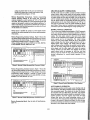
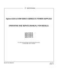
REVERSE CURRENT LOADING
An ective Iead oonneoted to the power supply may actually
deliver a -revers:EI .ourrent. t,o the power supply during a 'portion
of Its 0psrfltI1'l9oycll13' 'All external source oan not be allowed to
pump current [nto fhe ~upply wlthout los~ of regulation and
pcsslble d,arr~ge to the cutput.cepacitor of the power supply.
To avoid these effects, It Is necesserv to preload the supply
with 8 dummy load resistor so that the power supply delivers'
ourrent throiJgh the entire operating oycle of the load devices;
'1
-
,.::.:.....:.:
...
r ~
'"
~
Ie.
.-
- - - ClIfl9tT Fl.(M C(.RN!3 t,.
.
NOTE: If remote sensJOg,
ccooect + Senselead 10
AnoOO~ide of diode
I\C'!!'
'.
1______
- - - ~
~
~
~
L
~+
~+S
.. ----------- ~-S
-
0
POWER
SUPPLY
BATTERY
- - - GUlfefT FtJ1II Dl.AN3I.
...
BATTERY CHARGING
The power supply's OVP circuit contains a crowbarSCR,whlch
effeotively short~ the output of the supply whenever the' O.VP
trips. If an external voltage sou roe suoh as a battery is connected across the output, and OVP I~advertently triggered, the .SCR
will oontlnuously sink a large current from the source: posSibly
damaging the supply. To avoid this a diode must be connected
in series with the output as shown in Figure 17.
JalVElOAO
Il€VICE
PO\YER
·st.l'!'t.V
Since series regulator transistors cannot withstand reverse
voltage, another diode is conneoted across the series transistor.
Thlsdiodeproteotsthe series regulators ·11'1 parallel or autoparallel operation if one supply of the parallel combination is
turned-on before the othar.
I
~
-
r
•
Figure 16. Revers8 Current Loading Solution
Figure 17. Recommended Protection Ciroult for Battery Charging
OUTPUT CAPACITANCE
An Internal cepeottcr, corrnected.acrcee the output terminals of
the po~~r ,upply, helps to supply high·ourrent pulses of short
duration,durln.gconstant -voltage operation. Any capacitance
added externally wlllimprove the pulse current oapability, but
will deorease the safety provided by the current 'limiting circuit.
A high-current pulse may damage load oomponents before the
average output ourrent Is large enough to cause the current
limiting clrc.~it to operate.
The effect of the output oapacitor during constant current
operation are as follows:
8.
The output impedanoe of the power supply decreases with
1-14