1
RECORD THIS UNIT INFORMATION
FOR FUTURE REFERENCE:
Model Number
Serial Number
ADB Model Number
ADB Serial Number
Date Purchased
Roof Top Unit
USA
SERVICE OFFICE
Dometic, LLC
2320 Industrial Parkway
Elkhart, IN 46516
574-294-2511
CANADA
Dometic, LLC
46 Zatonski, Unit 3
Brantford, Ontario
CANADA N3T 5L8
519-720-9578
For Service Center
Assistance Call:
800-544-4881
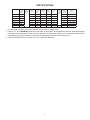
Description
Model
Use With Air
Distribution
Box
Model
3107210.XXX
Air Conditioner
457915
459516
Air Conditioner
459530
3313189.000 Cool/Furn White
3313189.015 Cool/Furn Black
Heat Pump
459156
3313189.023 Cool/Furn/HP White
3313189.031 Cool/Furn/HP Black
Heat Pump
459196
3313189.064 Cool/Furn/HP White
3313189.072 Cool/Furn/HP Black
SZLCD Control
3313189.000 Cool/Furn White
3313189.015 Cool/Furn Black
3313189.049 Cool/Furn/HS White
3313189.056 Cool/Furn/HS Black
This unit is designed for OEM installation.
! AVERTISSEMENT
This manual must be read and
understood before installation,
adjustment, service, or maintenance is performed. This unit must
be installed by a qualified service
technician. Modification of this
product can be extremely hazardous and could result in personal
injury or property damage.
Lire et comprendre ce manuel avant de
procéder à l’installation, à des réglages,
de l’entretien ou des réparations.
L’installation de ce produit doit être
effectuée par un réparateur qualifié.
Toute modification de ce produit peut
être extrêmement dangereuse et
entraîner des blessures ou dommages
matériels.
MODELS
INSTALLATION INSTRUCTIONS
REVISION
Form No. 3313433.025 4/11
(Replaces 3313433.017)
(French 3313434.023)
©2011 Dometic, LLC
LaGrange, IN 46761
457915.30X
457915.70X
459156.70X
459196.70X
3313433.025
Important: These instructions must
stay with unit. Owner read carefully.
459516.30X
459516.70X
459530.70X
SAFETY INSTRUCTIONS
GENERAL INFORMATION
A. Product features or specifications as described or illustrated are subject to change without notice.
This manual has safety information and instructions to help users eliminate or reduce the risk
of accidents and injuries.
B. This air conditioner/heat pump (hereinafter referred to
RECOGNIZE SAFETY INFORMATION
as the "unit") is designed for:
1. Installation on a recreational vehicle during the
time the vehicle is manufactured.
2. Mounting on the roof of a recreational vehicle.
3. Roof construction with rafters/joists on minimum
of 16 inch centers.
4. Minimum of 2 inch and maximum of 4 inches distance between roof to ceiling of recreational vehicle.
C. The ability of the air conditioner to maintain the de
This is the safety alert symbol. It is used to alert
you to personal injury hazards. Obey all safety
messages that follow this symbol to avoid possible injury or death.
UNDERSTAND SIGNAL WORDS
A signal word, when used with the safety alert
symbol, will identify a safety hazard and its level
of risk for personal injury. A signal word, without
the safety alert symbol, will be used for property
damage messages only.
sired inside temperature depends on the heat gain of
the RV.
Some preventative measures taken by the occupants
of the RV can reduce the heat gain and improve the
performance of the air conditioner. During extremely
high outdoor temperatures, the heat gain of the vehicle may be reduced by:
1. Parking the RV in a shaded area
2. Using window shades (blinds and/or curtains)
3. Keeping windows and doors shut or minimizing
usage
4. Avoiding the use of heat producing appliances
Operation on High Fan/Cooling mode will give optimum or maximum efficiency in high humidity or high
outside temperature.
Starting the air conditioner early in the morning and giving
it a "head start" on the expected high outdoor ambient will
greatly improve its ability to maintain the desired indoor
temperature.
WARNING indicates a hazardous situation which, if not avoided, could result
in death or serious injury.
For a more permanent solution to a high heat gain, accessories like Dometic outdoor patio and window awnings
will reduce heat gain by removing the direct exposure to
the sun. They also add a nice area to enjoy company during the cool of the evening.
CAUTION, used with the safety alert symbol, indicates a hazardous situation
which, if not avoided, could result in minor or
moderate injury.
D.Condensation
NOTICE is used to address
practices not related to personal injury.
Note: The manufacturer of this unit will not be responsible
for damage caused by condensed moisture on ceilings or
other surfaces. Air contains moisture and this moisture
tends to condense on cold surfaces. When air enters the
RV, condensed moisture may appear on the ceiling, windows, metal parts, etc. During normal operation this unit
removes moisture from the air. Keeping doors and windows closed when this air conditioner is in operation will
minimize condensed moisture on cold surfaces.
Read and follow all safety information and
instructions to avoid personal injury.
2
SPECIFICATIONS
Model No.
Nominal
Capacity
(BTU HR)
Cooling
Electrical
Rating
120 VAC
60Hz. 1PH
Compressor Compressor Fan Motor Fan Motor
Rated Load
Locked
Rated Load
Locked
Amps
Rotor
Amps
Rotor
Amps
Amps
Refrigerant
R-410A
(Oz.)
457915.30X
13,500
12.4
61.0
2.5
5.8
20.0
457915.70X
13,500
12.4
63.0
2.5
5.8
18.0
459156.70X
15,000
13.3
66.0
2.0
5.6
459196.70X
15,000
13.3
66.0
2.0
459516.30X
15,000
13.4
64.0
459516.70X
15,000
13.3
459530.70X
N/A
8.6
Minimum
Wire Size*
12 AWG
Copper
Up to 24'
AC Circuit
Protection
***Installer
Supplied
Minimum
Generator
Size**
1 Unit / 2 Units
20 Amp
3.5 KW / 5.0 KW
20 Amp
3.5 KW / 5.0 KW
29.0
20 Amp
3.5 KW / 5.0 KW
5.6
29.0
20 Amp
3.5 KW / 5.0 KW
2.0
5.6
27.5
20 Amp
3.5 KW / 5.0 KW
66.0
2.0
5.6
27.5
20 Amp
3.5 KW / 5.0 KW
50.0
2.5
5.8
20.0
15 AMP
2.5 KW / 4.0 KW
* For wire length over 24 ft., consult the National Electric Code for proper sizing.
** Dometic, LLC gives GENERAL guidelines for generator requirements. These guidelines come from experiences people
have had in actual applications. When sizing the generator, the total power usage of your recreational vehicle must be
considered. Keep in mind generators lose power at high altitudes and from lack of maintenance.
*** CIRCUIT PROTECTION: Time Delay Fuse or Circuit Breaker Required.
3
INSTALLATION INSTRUCTIONS
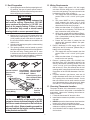
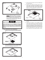
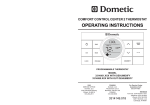
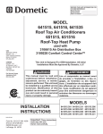
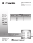
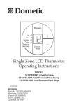
FIG. 1
A. Precautions
13-1/8"
Improper installation may damage equipment,
Dimensions Are Nominal
18"
1. Read Installation and Operating Instructions carefully before attempting to start this unit installation.
2. Dometic, LLC will not be liable for any damages
or injury incurred due to failure in following these
instructions.
3. Installation must comply with the National Electrical Code ANSI/NFPA-70 and CSA Standard C22.1
(latest edition) and any State or Local Codes or
regulations.
4. DO NOT add any devices or accessories to this
unit except those specifically authorized in writing
by Dometic, LLC.
5. This equipment must be serviced by qualified
personnel and some states require these people
to be licensed.
14-1/4" x 14-1/4"
(±1/8") Opening
Keep This Area Free Of Obstructions
Dimensions Are Nominal
B. Choosing Proper Location For The Unit
b. The roof must be designed to support 130
pounds when the RV is in motion. Normally a
200 lb. static load design will meet this requirement.
It is the responsibility of the installer of this
system to ensure structural integrity of the RV
roof. Never create a low spot on the roof where
water will collect. Water standing around the
unit may leak into the interior causing damage
to the product and the RV.
This unit is specifically designed for installation on the
roof of a recreational vehicle (RV). When determining
your cooling requirements, the following should be
considered:
• Size of RV;
• Window area (increases heat gain);
• Amount of insulation in walls and roof;
• Geographical location where the RV will be used;
• Personal comfort level required.
1. For one unit installation: The unit should be mounted
slightly forward of center (front to back) and centered from side to side.
2. For two unit installations: Install one unit 1/3 and
one unit 2/3’s from front of RV and centered from
side to side.
It is preferred that the unit be installed on a relatively flat
and level roof section measured with the RV parked on a
level surface, but up to a 15° tilt is acceptable.
29-7/8"
34-7/8"
could endanger life, cause serious injury and/
or property damage.
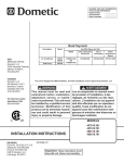
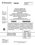
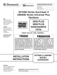
c. Check inside the RV for air distribution box
obstructions (i.e. door openings, room dividers,
curtains, ceiling fixtures, etc.) See FIG. 2.
FIG. 2
20"
22-1/2"
2-1/2"
Dimensions Are Nominal
3. After Location Has Been Selected:
a. Check for obstructions in the area where unit
will be installed. See FIG. 1.
11-1/4"
11-1/4"
2-3/4"
20"
3"
4
14-1/4" x 14-1/4"
(±1/8") Opening
Dimensions Are Nominal
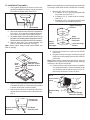
D. Wiring Requirements
C. Roof Preparation
1. Opening Requirements - Before preparing the ceiling opening, the type of system options must be
decided upon. Read all of the following instructions
before beginning the installation.
There may be electrical wiring between the
roof and the ceiling. Disconnect 120 VAC
power cord and the positive (+) 12 VDC terminal at the supply battery. Failure to obey
this instruction may create a shock hazard
causing death or severe personal injury.
2. Mark a 14-1/4" x 14-1/4" (±1/8") square on the roof
and carefully cut the opening. The 14-1/4" x 14-1/4"
(±1/8") opening is part of the return air system of
the unit and must be finished in accordance with
ANSI A119.2.
3. Using the roof opening as a guide, cut the matching
hole in the ceiling.
4. The opening created must be framed to provide
adequate support and prevent air from being drawn
from the roof cavity. Framing stock 3/4" or more
in thickness must be used. Remember to provide
an entrance hole for power supplies, 3 conductor
cable, and furnace wiring (if applicable).
FIG. 3
Do Not Cut Roof
Structure Or
Rafters
3/4" Min.
Good-Rafters Good LocationSupported By Between Roof
Cross Beams Rafters
Frame Opening So It
Won't Collapse When
Bolting Down Unit
Leave Access For Power
Supply Wiring
1. Route a copper, with ground, 120 VAC supply
wire from the time delay fuse or circuit breaker
box to the roof opening. The proper size wire can
be determined from chart on page 3.
a. This supply wire must be located in the front
portion of the 14-1/4" x 14-1/4" (±1/8") opening.
b. The power MUST be on an appropriately
sized separate time delay fuse or circuit
breaker. The proper size protection can be
determined from the chart on page 3.
c. Make sure that at least 15" of supply wire extends into the roof opening. This insures an
easy connection at the junction box.
d. Wiring must comply with the National Electrical Code ANSI/NFPA-70 and CSA Standard
C22.1 (latest edition) and any State or Local
Codes or regulations.
e. Protect the wire where it passes into the
opening with approved method. See paragraph "d" above.
2. Route a dedicated 12 VDC supply wire (18-22
AWG) from the RV's converter (filtered side) or
battery to the roof opening.
a. This supply wire must be located in the front
portion of the 14-1/4" x 14-1/4" (±1/8") opening.
b. Make sure that at least 15" of supply wire extends into the roof opening.
3. Route a 3 conductor cable, 18 to 22 AWG, from
the Single Zone LCD (hereinafter referred to as
SZLCD) thermostat mounting position into the
14-1/4" x 14-1/4" (±1/8") roof opening. Make sure
that at least 15" of the wire extends into the roof
opening and 6" extend from the wall at the mounting position of the SZLCD thermostat. See Section E.
4. If system includes a gas furnace, route two 18
gauge thermostat wires from the furnace to the
roof opening of the unit that will control it. If more
than one furnace is to be used, route the second
set of thermostat wires to the second unit. Make
sure that 15" of wire extends into the opening.
E. Choosing Thermostat Location
15" Min. At
Front Of
Opening
It is the responsibility of the installer of this
system to ensure structural integrity of the RV
roof. Never create a low spot on the roof where
water will collect. Water standing around the
unit may leak into the interior causing damage
to the product and the RV.
5
The proper location of the thermostat is very important to ensure that it will provide a comfortable RV
temperature. Observe the following rules when selecting a location:
1. Locate the thermostat 54" above the floor.
2. Install the thermostat on a partition, not on an outside wall.
3. NEVER expose the thermostat to direct heat from
lamps, sun or other heat producing items.
4. Avoid locations close to doors that lead outside,
windows or adjoining outside walls.
5. Avoid locations close to supply registers and the
air from them.
F. Thermostat and Thermostat Cable Installation
G. Placing The Unit On The Roof
1. SZLCD Thermostat
Personal injury hazard. This unit weighs approximately 100 pounds. To prevent back
injury, use a mechanical hoist to place unit
on roof. Failure to obey this warning could
cause severe personal injury.
Note: Wire colors listed for the three conductor cable
match the wire colors in the harness at the SZLCD control
box. Available wire colors may vary.
FIG. 4
12V-
COMMS
12V+
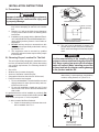
1. Remove the unit from the carton and discard carton.
2. Place the unit on the roof.
3. Lift and place the unit over the prepared opening
using the gasket on the unit as a guide. See FIG.
5.
FIG. 5
Front
a. Remove the cover from the SZLCD thermostat. Depress tab on bottom of thermostat
and separate it from the base.
b. Insert the previously run three (3) conductor
cable through the hole in the base assembly.
c. Cut back the outer cable shield approximately 3 inches and strip 1/4" insulation from each
wire.
d. Mount the thermostat level on the wall using
the screws provided.
e. Make the following connections to the thermostat. See FIG 4.
• Red/white wire to the 12V+ terminal
• Black wire to the 12V– terminal
• Orange wire to the "COMMS" terminal
f. Inspect all connections to make sure they are
tight and not touching any other terminals or
wires.
g. Push the wires back through the base into
the wall. Place cover on the thermostat and
push until an audible click is heard.
Do Not Slide
Property damage hazard. Do not slide the
unit. Failure to obey this warning may damage the neoprene gasket attached to the bottom and create a leaky installation.
4. Place the air distribution box kit inside the RV.
This box contains mounting hardware for the unit
and will be used inside the RV.
This completes the outside work. Minor adjustments can
be done from inside the RV if required.
6
H. Installation Preparation
Note: In some applications it may be necessary to extend the
6 pin cable. Order cable number 3105584.001 if needed.
1. Check gasket alignment of the unit over the roof
opening and adjust if necessary. Unit may be moved
from below by slightly lifting. See FIG. 6.
7. Measure the ceiling to roof thickness:
a. If distance is 2"-3", remove perforated tabs
from lower duct. See FIG. 9.
b. If distance is 3"-4", install ducts as received.
See FIG. 9.
c. If distance is 4"-6", use optional 3106775.004
Duct Adaptor and 3100895.006 Bolt Kit.
FIG. 6
FIG. 9
Roof Gasket
2. Remove air distribution box and mounting hardware
from carton. The upper duct is shipped inside the
lower duct which is part of the ceiling template.
3. All models listed in this manual will use a four (4)
bolt pattern for installing the air distribution box kit.
These bolts are furnished in the SZLCD control kit.
4. Remove upper duct from ceiling template and
locate it over blower discharge. See FIG. 7.
Note: Edges without flanges install toward REAR and
SIDE of opening.
Upper Discharge
Air Duct
Step b
Use As
Packaged
Step a
Remove At
Perforation
Lower Discharge
Air Duct
8. Remove the junction box cover from the SZLCD
control box.
9. Plug the electrical cord (6 pin connector) from the
upper unit into the mating connector in the SZLCD
control box.
Note: Plastic SZLCD control boxes will need to have the
supplied freeze control sensor plugged into the matching
connector in the SZLCD control box.
10. Insert the freeze control sensor into the evaporator
coil fins approximately 1" above the bottom of the
coil fins and on the left side as shown in FIG. 10.
Bend fins over sensor to secure in place.
FIG. 7
Upper
Duct
Screw
Lower
Duct
Side Without
Tabs Are To Rear
And Side Of Unit
Screw
FIG. 10
Freeze Control
Sensor
5. Use two (2) sharp pointed #10 sheet metal screws
to hold duct to base pan. Screw holes are provided
in bottom of base pan for these screws.
6. Reach up into the return air opening and pull the
unit electrical cord down for later connection. See
FIG. 8.
Remove Hang
Tag
FIG. 8
Center Unit
From Below
Measure Ceiling
Thickness
Pull Down
Electrical Cord
7
Route Up Through
Return Air Opening
I. Wiring The System
1. 120 VAC Power Supply Connection
Disconnect 120 VAC. Failure to obey these
instructions could create a shock hazard
causing death or severe personal injury.
J. Installing The Unit
This product is equipped with a 3 wire (grounded) system for protection against shock hazard. Make sure that the unit is wired and that
you connect into a properly grounded 120 VAC
circuit and the polarity is correct. Failure to
do so could result in death, personal injury
or damage to the equipment.
d. Connect the red/white wire from the SZLCD
control box to wire of the three wire cable that
goes to thermostat 12V+ terminal.
e. Connect the orange wire from the SZLCD
control box to wire of the three wire cable that
goes to thermostat COMMS terminal.
1. Install the SZLCD control box on the ceiling template as shown in FIG. 11. Drive two (2) #6 x 3/8"
(plastic control box) or #10 x 3/8" (metal control
box) blunt point Phillips head screws (provided)
through the ceiling template into holes in the
SZLCD control box to hold into place.
FIG. 11
SZLCD
Control Box
a. Route the 120 VAC supply wire through the
strain relief in the SZLCD control box. Tighten
strain relief, making sure enough wire is inside SZLCD control box to connect with unit
120 VAC wires.
b. Connect the white to white; black to black;
and green or bare copper wire using appropriate size wire connectors. See chart on
page 3.
c. Push the wires into the SZLCD control box
and install the cover with the four blunt point
screws provided.
2. Low Voltage Wire Connections At The SZLCD
Control Box.
Disconnect the positive (+) 12 VDC terminal
at the supply battery. Damage to equipment
could occur if the 12 VDC is not shut off.
Ceiling Template
2. If your installation includes the optional electric
heat kit, (457915 & 459516 models only) install it
at this time. Follow the instructions with the heat
package for its installation procedure.
3. Install ceiling template by sliding the lower duct
over upper duct.
4. Hold the ceiling template up to the 14-1/4" x
14-1/4" (±1/8") opening with one hand and with
the other, install the four (4) 1/4" mounting bolts
through the template and into the unit base pan.
a. Tighten all four (4) mounting bolts until they
touch the template but are not tight. Check
alignment. There should be an equal opening on each side and the rear flange must be
tight against the roof opening.
FIG. 12
Mounting Bolts
Note: If a solar panel is to be installed see instructions
packaged with solar panel option.
Note: Plastic SZLCD control boxes only. Plug the supplied 4 wire harness and the supplied 2 blue wires into
their matching connectors in the SZLCD control box.
a. Connect the previously run +12 VDC supply
wire to the red wire from the SZLCD control
box.
b. Connect the previously run –12 VDC supply
wire to both the black wire from the SZLCD
control box and to wire of the three wire cable
that goes to the thermostat 12V– terminal.
c. Connect the previously run furnace thermostat wires (if applicable) to the blue wires
coming from the SZLCD control box.
Mounting Bolts
Discharge
Air Duct
Duct Screws
8
b. With the ceiling template flat against the ceiling install six (6) wood screws (installer supplied) at an angle, so as to stretch and flatten the template. Three across the front and
three across the back of the template. See
FIG. 13.
FIG. 13
3. Snap hole plug into place at rear of air distribution
box. See FIG. 16
4. There are four optional mounting holes on the
outer edge of the return air opening for which
screws are not provided. These are only required
where an uneven ceiling does not allow proper
fitting of the air distribution box. See FIG. 16.
Fig. 16
Wood
Screw
Wood
Screws
c. EVENLY tighten the bolts to a torque of
40 to 50 inch pounds. This will compress
the roof gasket to approximately 1/2". The
bolts are self locking so further tightening
is not necessary. See FIG. 13.
Plug
If bolts are left loose there may not be an adequate roof seal or if over tightened, damage
may occur to the unit base or ceiling template.
Tighten to torque specifications listed in this
manual.
K. Air Distribution Box Installation
1. Remove return air grill from air distribution box by
pulling in on half round finger catches. See FIG.
14.
FIG. 14
Half Round
Catches
Return Air Grill
2. Hold air distribution box up to ceiling template
and install three (3) #10 x 3/8" screws at air distribution box mounting point. See FIG. 15.
Fig. 15
Screws
9
Wood
Screw
5. Reinstall return air grill and filter into air distribution box.
6. Verify that all features of the installed system
work. Please read Unit User’s Guide or Operating
Instructions before proceeding. Check fan speed,
heat strip (if applicable), furnace operation (if applicable) and cooling operation. If the features do
not work disconnect the 12 VDC and 120 VAC
power supplies and verify that all wiring is correct.
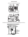
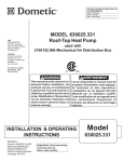
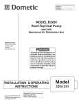
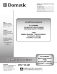
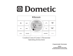
WIRING DIAGRAM
457915, 459516 & 459530 Unit Wiring Diagram
459156 & 459196 Unit Wiring Diagram
3313189.000 & 3313189.015 Single Zone LCD Control Kit Wiring Diagram Cool/Furnace
(/(&&211
)520$&
,)7+,6352'8&7,66833/,('%<$:,5,1*6<67(07+$7,1$&&25'$1&(:,7+
&$1$',$1(/(&75,&&2'(3$57&$1'7+(1$7,21$/(/(&75,&&2'(
$16,1)3$125(48,5(67+(,167$//$7,212)$1(48,30(17*5281',1*
&21'8&72525&21'8&72567(50,1$/625*5281'6&5(:6)257+,6
385326(0867%(,167$//('
*51<(/
:+7
5('
%/./,1(
*51<(/($57+
:+71(87
%/.
%/8
%/8
.5(/$<
12
%/.
5('
)5((=(6(1625
-
&20
%/.
<
<
9$&
+=2
86(&233(5
&21'8&7256
21/<
-
5('
5(':+7
%/.
25*
9
972
767$7
9
&200
<
)851$&( <
%/8
<
)851$&( <
%/8
10
` 9
6833/<
`
72
767$7
),(/':,5,1*
)$&725<:,5,1*
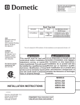
WIRING DIAGRAM
3313189.049 & 3313189.056 Single Zone LCD Control Kit Wiring Diagram
Cool/Furnace/Heat Strip
$&
&211(&7,21
&200767$7
9767$7
)851$&(
)851$&(
96833/<
96833/<
9767$7
*51<(/
:+7
5('
1&
%/.
%/8
%/.
<
25*
5(':+7
%/:7
%/:7
5('
%/.
<
-
3$571R
)5((=(
6(5,$/1R
6(1625
)2586(:,7+$,5&21',7,21(5
- )25$&:,7+237,21$/+($7675,3
&20
3$66('
',(/(&75,&
&20
12
+($7675,3
&211(&7,21
6323/$567
9$&+]2
/$*5$1*(,1
9$&
+=2
86(&233(5
&21'8&7256
21/<
12
:+7
1$
*5<
),(/':,5,1*
)$&725<:,5,1*
<
<
)$1/2 )$1+,
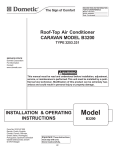
3313189.023 & 3313189.031 Single Zone LCD Control Kit Wiring Diagram Cool/Furnace/HP
(/(&&211
)520$&
,)7+,6352'8&7,66833/,('%<$:,5,1*6<67(07+$7,1$&&25'$1&(:,7+
&$1$',$1(/(&75,&&2'(3$57&$1'7+(1$7,21$/(/(&75,&&2'(
$16,1)3$125(48,5(67+(,167$//$7,212)$1(48,30(17*5281',1*
&21'8&72525&21'8&72567(50,1$/625*5281'6&5(:6)257+,6
385326(0867%(,167$//('
*51<(/
:+7
5('
*5<
%/.
%/8
9$&
+=2
86(&233(5
&21'8&7256
21/<
%/./,1(
*51<(/($57+
:+71(87
%/8
.5(/$<
12
%/.
&20
%/.
5('
*5<
<
<
-
-
287'2257(03
6(1625
-
)5((=(6(1625
5('
5(':+7
%/.
25*
9
972
767$7
9
&200
<
)851$&( <
%/8
<
)851$&( <
%/8
` 9
6833/<
`
72
767$7
),(/':,5,1*
)$&725<:,5,1*
3313189.064 & 3313189.072 Single Zone LCD Control Kit Wiring Diagram Cool/Furnace/HP
(/(&&211
)520$&
,)7+,6352'8&7,66833/,('%<$:,5,1*6<67(07+$7,1$&&25'$1&(:,7+
&$1$',$1(/(&75,&&2'(3$57&$1'7+(1$7,21$/(/(&75,&&2'(
$16,1)3$125(48,5(67+(,167$//$7,212)$1(48,30(17*5281',1*
&21'8&72525&21'8&72567(50,1$/625*5281'6&5(:6)257+,6
385326(0867%(,167$//('
*51<(/
:+7
5('
*5<
%/.
%/8
%/./,1(
*51<(/($57+
:+71(87
%/8
.5(/$<
12
9$&
+=2
86(&233(5
&21'8&7256
21/<
%/.
&20
-
287'2257(03
6(1625
-
)5((=(6(1625
5('
5(':+7
-
%/.
25*
9
972
767$7
9
&200
%/.
<
5('
<
*5<
<
)851$&( <
%/8
<
)851$&( <
%/8
11
` 9
6833/<
`
72
767$7
),(/':,5,1*
)$&725<:,5,1*