1
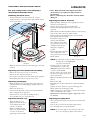
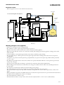
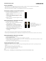
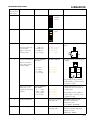
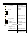
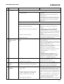
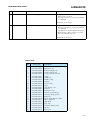
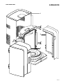
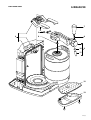
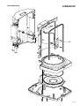
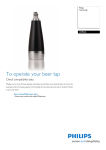
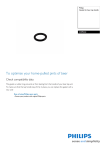
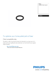
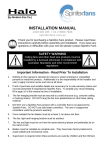
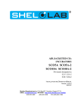
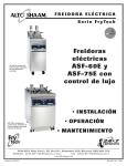
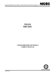
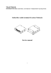
Perfect Draft
HD3620/20
Philips Domestic Appliances and Personal Care
Service Manual
PRODUCT INFORMATION
TECHNICAL INFORMATION
- This product meets the requirements regarding
interference suppression on radio and TV.
- After the product has been repaired, it should function
properly and has to meet the safety requirements as
officially laid down at this moment.
- Power
- Power consumption :
- Cool down period average
(KEG 23 °C -> 3 °C)
- Standby period
(KEG on 3 °C)
- Voltage
-
Flow rate
Contents Keg
Colour setting
SAP coding
: 70 W
: 0.062 kWh
: 0.042 kWh
: 100 - 120 V - 50/60 Hz
200 - 240 V - 50/60 Hz
: 2 L per minute
: 6L
: Black/Metal
: HD3620/20
OPTIONAL (accessories)
- No specific issues
Published by Philips Domestic Appliances and Personal Care
07/01
Printed in the Netherlands
© Copyright reserved
Subject to modification
DISASSEMBLY- AND RE-ASSEMBLY ADVISE
For your safety first be sure the plug is
disconnected from the mains!
Removing the back cover:
- To remove the back cover, first remove the 4 screws.
- Open both doors, at the upper/lower right and left side the
screws can be found.
HD3620/20
* Note: When the Fan became defect also Peltier
element has to be replaced or fully checked on
performance.
Due to overheating also the Peltier element will be
damaged.
Replacing the Peltier element:
- When the Peltier element has to be replaced, first remove
the back cover and Fan assy.
- Unscrew the 2 screws located on the heat sink.
- The heat sink including Peltier element can now be
removed.
- With a small screwdriver the Peltier element can be removed
from the heat sink, some force maybe needed.
- Before placing the new Peltier element, clean the chiller
plate and heat sink thoroughly.
- Provide heat sink paste on
the heat sink and chiller
plate. With a plastic comb
(or plastic like a credit card)
carefully provide the heat
sink paste as equable as
possible.
- Place the new Peltier element
on the chiller plate at the
same position of the removed
Peltier element.
Picture 3.
Picture 1.
- When the back cover has been removed all parts can easy be
reached.
Replacing the Lever Connector Assembly:
- Remove the screw that you can see on the front.
- Remove the hose from the pump unit.
- Now the lever assembly can be removed from the appliance.
- Reassembling follow above steps in reverse order.
-
-
-
NOTE! It is important to place the Peltier element with
the right side on the chiller plate.
(see picture 4 for details)
In other words, the cooling side
of the Peltier has to point to the
chillerplate and the warm side has
to point to the heat sink.
Detail to check is the Colour of the
wires must be equal positioned see,
picture 4 for detail.
Make sure the Peltier element is well
Picture 4.
placed.
Place the heat sink.
Hold and place the heat sink with force against the Peltier
element.
Tighten the screws alternate, to prevent damaging the
Peltier element for mounting lop-sided.
While screwing wait some seconds so that the heat sink past
can be settled between the surfaces.
Maximum force that maybe applied to tighten the screws
are: 0.6 Nm.
Replacing the Display:
- When the display has to be replaced for some reason, the
complete Left door including display and flat cable has to
be replaced.
- Remove the back cover.
- Disconnect the flat cable connector from the main PCB
that is coming from the right door.
- Unscrew the two screws that are holding the door.
- To re-assembly carry out steps backwards.
-
Replacing the Fan assy.
- When the Fan has to be
replaced, unscrew the 4 posi
screws and disconnect the
connector of the Fan.
- When re-assemble the fan
assy, be sure that the airflow
(see arrow on the Fan) is
appointing to the heat sink.
Replacing the pump unit:
- Start with disconnecting the air pressure hose and electrical
connections.
- Unscrew the 3 screws from the plastic pump bracket.
- To re-assembly carry out steps backwards.
Picture 2.
-
NOTE! To prevent leakage at the connection side of the
hose, cut a small piece off the end of the hose.
2-13
REPAIR INSTRUCTIONS
HD3620/20
Electrical circuit:
- When the appliance does not work, check the electrical circuit.
Beer outlet
Process block diagram of the appliance
Pressure
Sensor
PCB
Air
pump
M
10.5 V
J11 J6 J12
J14
Keg
Compressed
air
J10
Interface board
(rear panel)
Power supply
NTC
Display PCB
(Front panel)
J1
Keg fill air
release
Air inlet
J9
Keg present
switch
J8
Display
J7
Heatsink
J2
M
J5
J3
Beer in
plastic bag
J4
Fan
Chillerplate
Peltier
Mains
(120 V or 230 V)
Picture 5.
Working principle of the appliance
- Hereby a short description of the working principle.
- Beer, the Beer is stored in a plastic bag inside the Keg, see picture 5.
- The Beer only comes in contact with the tube connector and never with the appliance.
- When the tap unit and tube connector are connected on the Keg and the Keg is placed in the appliance, the Keg present switch
will be activated.
- Once the appliance is activated after approximately 10 seconds you will hear a pump running.
- The task of this pump is to fill the space between the plastic bag and the walls of the Keg with air and create an overpressure
(± 1500 mBar).
- Through the over pressure around the plastic bag (comparable like you squeeze into the plastic bag) the Beer will be pressurized
(sort of ) as well.
- By pulling the tap handle the tube connector hose will become opened and the Beer will flow out of the plastic bag via the tube
connector in to the glass.
- After this cycle the pump will start running to get back in the overpressure situation like described before.
- When the Keg present switch has been actuated also the cooling process (Peltier element) will be started and display functions
become visible.
- The temperature is measured by a NTC located near the Keg present plunger.
- The volume indication is based on the principle of a pressure drop measured by the pressure sensor.
The speed and value of the pressure drop will be calculated in an algorithm, the outcome will be represented as volume on the
display.
- When pouring Beer, the pressure in the KEG will decrease, the amount the pressure decrease in a period of time will be calculated
through the system and indicated as volume on the display.
- The volume indication is dived in 9 steps.
- The Beer Freshness indicator is a day counter (24 h) and can be adjusted with the + and − button. (default 30days)
3-13
REPAIR INSTRUCTIONS
HD3620/20
Service testroutines
- This appliance has been equipped with special service routines to be able to check several functions of the appliance.
- Below the necessary steps will be described to enter into the service mode.
- Please follow the instructions carefully to avoid damaging the electronic circuit of the appliance.
Read out the software version of the appliance.
1. Disconnect the appliance from mains.
2. Keep the + button at the display pressed and connect
appliance to the mains.
3. Keep the + button pressed and readout the software
version (number indicated for example 21 = version
2.1), see example.
4. When the + button is released the appliance returns
to the normal state.
Putting the appliance into Display test mode.
1. Disconnect the appliance from mains.
2. Keep the + and − button at the display pressed and
connect appliance to the mains.
3. The display test starts. (countdown temperature
indication from 20 to 3 then volume bars will be
decreased one by one and after that the freshness day
counter will be counting down from 30 to 0.
4. This process will continue over and over again until
the appliance will be unplugged!
See examples.
20 C
0
30
3C
0
Normal VolDisp
Green segment if TempDisp < 5 °C
Red segment if TempDisp ≥ 5 °C
Normal FreshDisp
!
- Above 2 routines can be used to check the software version and working of the Display.
- If internal parts like NTC/Pump, Peltier or FAN must be checked also the service test routines, see further can be carried out.
Putting the appliance into Service test mode.
1. Disconnect the appliance from mains.
2. Remove the KEG (if placed)
3. Keep the KEG present switch pressed and connect the appliance to the mains.
4. When the display comes up release the KEG present switch. (if the KEG present switch will be released within 2 sec after
powering up the service mode is entered.
5. If above steps succeeded the appliance will show the current software version.
Stepping through the Service mode.
- Now the service mode is entered it is possible by pressing and releasing the KEG present switch to step through the service
routines.
- The list below shows all the possible Service Modes.
- After step mode 10, the routine jumps back to step mode 0.
- Exit the routine by unplugging the appliance.
Note:
For step mode 4 - 5 the KEG present switch must kept pressed other wise the Fan will not work!
4-13
REPAIR INSTRUCTIONS
Stepmode
Test
(Press & release
KEG switch)
0
Show software version
1
Display test
HD3620/20
Stimulus
Response
Shows
software
version
88 C
0
88
2
Remark
2 digits. E.g. 21 = version 2.1
All segments
are lit
!
Temperature test
NTC simulated value
Display indicates:
Disconnect NTC (J6)
from the PCB.
Apply to (J6) below
resistance values.
1. 1 kΩ (1%)
2. 10 kΩ (1%)
3. 51 kΩ (1%)
4. out of range
1.
2.
3.
4.
1≅C
2≅C
3≅C
−
Replace NTC sensor by dummy
sensor.
(red color)
(green)
(red)
(red)
J6
19k
5k
3
Pressure measurement
Pressure simulated
value (mV)
Freshness indicates:
* Replace pressure sensor and apply
dummy.
1
Disconnect Pressure
sensor (J14) Connect
external dummy.
J14
1.
2.
3.
4.
0 - 2mV
4 - 6mV
8 - 10mV
out of range
1.
2.
3.
4.
1
2
3
−
(yellow)
(yellow)
(yellow)
(yellow)
4k7
4k7
4k7
4k7
1k
* Depending on the possibilities
either dummy or pressure can be
applied for testing.
Apply to the air inlet
of the sensor or air
coupling the following
pressures.
Pressure simulated
value (mBar)
1. 0
- 300
2. 600 - 900
3. 1200 - 1500
4. out of range
1.
2.
3.
4.
1
2
3
−
(yellow)
(yellow)
(yellow)
(yellow)
* Apply calibrated air pressure to
the Pressure sensor or by the Air
coupling hole.
* Depending on the possibilities
either voltage or pressure can be
applied for testing.
4
Fan motor low level
1. Fan starts running.
2. Display Off.
Keep KEG switch pressed!!
Fan runs on (80%) level
Voltage across fan:
~7 - 8.5 Vdc / ~0.25 Vrms
5
Fan motor high level
1. Fan starts running.
2. Display Off.
Keep KEG switch pressed!!
Fan runs on (100%) high level
Voltage across fan:
~10.5 Vdc / ~0 Vrms
5-13
REPAIR INSTRUCTIONS
Stepmode
Test
(Press & release
KEG switch)
HD3620/20
Stimulus
Response
Remark
6
Peltier medium
1. Peltier starts cooling. Peltier runs on medium level (~50%)
2. Display Off.
Voltage across Peltier:
~6.0 Vdc / ~4.0 Vrms
Current through Peltier:
~4 A rms
8
Peltier high
1. Peltier starts cooling. Peltier runs on high level (100%)
2. Display Off.
Voltage across Peltier:
~10.5 Vdc / ~0.0 V rms
Current through Peltier:
>4.7A rms (lower=defect Peltier)
9
Pump test
1. Pump starts.
2. Display Off.
10
Freshness indicator
and + & − button test
With the + & −
buttons in the
display the Freshness
day counter can be
changed.
(30 – 1)
30
Procedure for checking cool down performance Peltier element.
- To ensure the Cool performance of the Peltier element is according specification the below test procedure have to be carried out.
Preparations:
1. Switch the appliance off and let it stabilize until it reached room temperature.
2. Remove under the base in the middle the rubber cap.
3. Remove the isolation foam under the removed cap, until the chiller plate becomes visible.
- Perform the temperature measurement, when the unit has reached the room/environment temperature.
1. Place a contact temperature probe against the chiller plate were the cap was removed.
2. Block the air inlet coupling at the Keg side, see picture 6 for location.
Picture 6.
3.
4.
5.
6.
7.
Plug the appliance in the wall socket and bridge over the Keg present mechanically or electrically so the appliance will start.
When the appliance has started the pump will run shortly (in case the air inlet has been blocked properly)
Readout the temperature meter and note it down.
Keep the appliance switched on for 2 minutes, readout the temperature again.
If the temperature has decreased more then 6 °C, between the two measurements the cooling performance is OK, if not
please check again or replace peltier or Fan assy.
Final:
- When the appliance is checked and OK, fill the hole under the cap again with foam or other isolation material and place the cap
back under the base.
6-13
REPAIR INSTRUCTIONS
1
HD3620/20
Problem
Cause
Repair solution
Appliance doesn’t
work.
1. Power supply failed.
1. Check voltage output 10 V ± 0.5 V.
(replace power supply)
2. Check/replace micro switch.
2. Keg present switch failed.
DISPLAY no tap unit.
2
Software detection:
When the system detects no pressure rise during
running of the pump (duration measurement
10 seconds), the software will interpret that there
is no tap unit placed.
Checks:
• Place tap unit.
• Is the pressure sensor function correctly?
• Is air leakage noticeable in the system?
Faded background of VolDisp.
Green segment.
No FreshDisp.
DISPLAY leakage.
DISPLAY ERROR SIGNALS
Blinking faded background of VolDisp or
No FreshDisp.
Green segment if TempDisp < 5° C.
Red segment if TempDisp ≥ 5 °C.
DISPLAY no KEG /standby.
Software detection:
The KEG present/activation switch will give
input to the Interface board.
Checks:
• Is the micro switch function correctly?
Faded background of VolDisp.
Red segment.
No FreshDisp.
0
C
30
3
60 C
0
Software detection:
The system detects a pressure fall that is greater
than normal when pouring Beer, the software
will interpret that there is a leakage in the
system.
Measurement takes approximately 300 seconds.
Checks:
• Is the pressure sensor function correctly?
• Is air leakage noticeable in the system?
Temperature display reading cannot be trust.
Problem:
1. Display indicates 60 °C.
2. Display indicates 1 °C.
3. Display indication not in line with Keg
temperature.
1. NTC has short circuit.
2. NTC has open circuit.
3. See chapter SERVICE TESTROUTINES
step mode 2 how to check the system.
30
Blinking display or
pump is “to” often
activated.
(Air Leakage)
Check if air leakage is found internal the appliance.
1. Remove the Keg and tap unit.
2. Block the air Inlet coupling at the Keg side.
3. Actuate the KEG present switch after
±10 seconds the pump will start running
shortly (depending on air leakage).
4. Wait ± 300 sec.
5. Check if the pump is not running the air
leakage is probable external.
If the leakage is caused internally the following
parts must be checked.
1. Leakage hose and/or hose connections.
(Hairline cracks)
2. Leakage in air coupling.
3. Leakage in the pump and/or connections.
4. Defective air pressure sensor.
Air leakage external:
Parts that could cause the external air leakage
are: Tap unit, keg and air coupling.
1. Leakage in connection air coupling - Tap
unit.
2. Leakage in connection Keg - Tap unit.
3. Leakage in the Keg.
7-13
REPAIR INSTRUCTIONS
Problem
4
HD3620/20
Cause
Cooling problems.
Repair solution
Cool down process takes very long.
Check if the user conditions were carried out
according the DFU.
1. Check if there is 10 cm free space around the
appliance.
2. Check if the ambient temperature did not
exceed 32 °C.
3. Check if the fan is turning well and there is
no blockage caused by dust or other particles.
4. Check if the Fan is correct placed (air flow
direction)
Unit doesn’t cool down.
Possible root causes:
Check/replace the defective parts.
1. Peltier element became defect.
1. Perform the cooling test as described on
page 6.
2. Clean the NTC See chapter SERVICE
TESTROUTINES step mode 2 how to
check the system or see point 5 “Temperature
display reading cannot be trust” in the table
below.
3. Check if the fan is turning well and there is
no blockage caused by dust or other particles.
4. Exchange fan and Peltier element.
2. NTC sensor became polluted or defective.
3. Fan, heat sink is full of dust.
4. Fan became defect.
5
Temperature display
reading cannot be
trust.
System check by means of external temperature
meter.
1. Place temperature sensor next to the location
of the NTC assy.
2. Place keg and plug appliance on. For the best
result start measurement if appliance reached
display reading below 10 °C.
3. Read out the external temperature meter and
the display value of the appliance.
4. Subtract a 2.4 °C from the external
temperature reading and compare the values.
Deviation aloud +/− 1 °C, below 3 °C
− 1 °C / + 2 °C.
5. Example:
External indication temperature 7.4 °C
Display reading PerfectDraft system 5 °C
Conclusion (7.4 reading ext. – 2.4 offset
value) = 5 °C, appliance within spec.
6
Beer leakage.
1. Leakage spout side.
1. Check beer tube on hairline cracks or check
closing mechanism tap unit.
2. Check beer tube, tap unit and Keg.
2. Leakage on top of the Keg.
7
Condensation water
leakage.
Through the cooling process condensation water 1. Check if doors were closed properly. (If not
is formed and can drip under the appliance.
closed extra condensation will be build)
2. Check if the drip tray was well placed.
8
Beer volume
indication.
1. After usage of beer the volume indicates
100% again.
2. There is still beer left in the Keg and the
indicator is displaying no beer left 0 %.
3. Volume reading is not trustworthy.
4. Can I adjust the indication?
1. Through a voltage dip or appliance has been
switched off the default value (100 %) will
be displayed again. (after pouring one glass of
Beer the right volume will be displayed again)
2. This is normal appliance is adjusted that way.
3. The volume indication is a rough indication;
through air leakage problems the volume
indication become inaccurate.
4. No the volume indication cannot be adjusted.
8-13
REPAIR INSTRUCTIONS
Problem
9
HD3620/20
Cause
Repair solution
No foam on the Beer. Check the following conditions.
1. Temperature of the Beer must be below 9 °C.
2. Glasses have to be clean.
3. Beer tube connector is not properly installed
or is damaged.
Check DFU for more tips.
10
To much foam.
Check the following conditions.
1. Temperature of the Beer must be below 9 °C.
2. Beer tube connector is not properly installed
or is damaged.
3. Check if there is no air leakage in the system.
4. When the keg is almost empty it is possible
that only foam will come out.
Check DFU for more tips.
PARTS LIST
Pos
Service code
Description
1
2
3
4
5
9965 000 44301
9965 000 44302
9965 000 44303
9965 000 44304
9965 000 26126
Back cover
Right Door assy
Left Door/display assy
Connector/Lever assy
O-ring 11X2 Air inlet side
6
7
8
9
10
9965 000 32659
9965 000 44305
9965 000 26122
9965 000 44306
9965 000 26124
O-ring
Handle assy
Handle O-ring
Tap unit
Spout O-ring
11
12
13
14
15
9965 000 26123
9965 000 44307
9965 000 44308
9965 000 44309
9965 000 26117
Spout
Steel driptray cover
Driptray
NTC sensor assy
Pressure sensor PCB assy
16
17
18
19
20
9965 000 26115
9965 000 26116
9965 000 44310
9965 000 26111
9965 000 44311
Grommet. Pump position
Pump assy
Power supply HV 220 - 240 V
Micro switch assy
Main PCB
21
22
23
24
9965 000 32874
9965 000 26110
9965 000 26109
9965 000 26119
Drop ring
Grommet, FAN position
Fan assy
Peltier assy
9-13
EXPLODED VIEW
HD3620/20
1
2
3
10-13
EXPLODED VIEW
HD3620/20
7
5
4
8
6
10
9
11
12
13
11-13
EXPLODED VIEW
HD3620/20
14
12-13
EXPLODED VIEW
HD3620/20
15
16
17
18
19
20
21
22
23
24
13-13