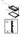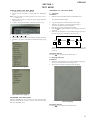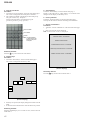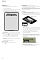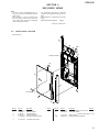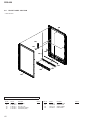
1
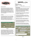
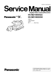
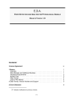
SERVICE MANUAL PRS-950 US Model Canadian Model Ver. 1.0 2010.10 Note: Be sure to keep your PC used for service and checking of this unit always updated with the latest version of your anti-virus software. In case a virus affected unit was found during service, contact your Service Headquarters. SPECIFICATIONS Model name PRS-950 Power source Built-in rechargeable battery: 3.7 V DC AC adapter: 5.0 V DC, 1,500 mA USB communication: Hi-Speed USB (USB 2.0 compliant) Battery life (continuous playback) Maximum Battery: Approx. 20,000 continuous page turns when reading only * * Measured using a text based content in ePub format and a fully charged battery, consecutive page-turns at approximately one second per page under the recommended operating temperature. Actual battery life may vary based on usage patterns and individual device. User available capacity Approx. 1.4 GB after initial setting Depending on size of pre-loaded excerpts, available memory capacity may vary. Operating/charging temperature 41°F to 95°F (5°C to 35°C) Dimensions (w/h/d) The contents of each book pre-loaded on this product are copyrighted works, edited with the cooperation of the publisher. Copyright laws prohibit copying the data of this product or the contents of this manual (illustrations, related documents, etc.) in whole or in part without the permission of the copyright holder. Additionally, use of the data of this product or the contents of this manual is not allowed without Sony’s permission except for personal use. Besides personal use, it is against the copyright law to use any audio or picture you recorded without prior consent of the copyright holder. Accordingly, Memory Stick™ media with content protected image or data can be only used within the law. Sony, the Sony logo, “BBeB”, “Reader”, “Reader Daily Edition” and their logos are either trademarks or registered trademarks of Sony Corporation. , “Memory Stick”, “Memory Stick PRO Duo”, “Memory Stick PRO-HG Duo”, “Memory Stick Duo”, “Memory Stick Micro”, “M2”, “MagicGate” and their logos are trademarks of Sony Corporation. Bitstream is a registered trademark, and Dutch, Font Fusion, and Swiss are trademarks, of Bitstream Inc. Microsoft, Windows, Windows Vista and Windows Media are trademarks or registered trademarks of Microsoft Corporation in the United States and / or other countries. Macintosh and Mac OS are trademarks of Apple Inc., registered in the U.S. and other countries. This PRS-950 contains Adobe® Reader® Mobile software under license from Adobe Systems Incorporated, Copyright © 1995-2009 Adobe Systems Incorporated. All rights reserved. Adobe and Reader are trademarks of Adobe Systems Incorporated. MPEG Layer-3 audio coding technology and patents licensed from Fraunhofer IIS and Thomson. This product includes software developed by the OpenSSL Project for use in the OpenSSL Toolkit. (http://www.openssl.org/) Copyright© 1998-2008 The OpenSSL Project. All rights reserved. This product includes cryptographic software written by Eric Young ([email protected]). This product includes software written by Tim Hudson ([email protected]). For details on OpenSSL License, refer to “END USER LICENSE AGREEMENT” in [About] at [Settings] menu on the Reader. Wi-Fi, the Wi-Fi CERTIFIED logo, WPA, WPA2 and Wi-Fi Protected Setup are trademarks or registered trademarks of Wi-Fi Alliance. The Wireless LAN functionality, has passed Wi-Fi certification and complies with the interoperability specifications established by WFA (Wi-Fi Alliance). Approx. 5 1/8 × 7 7/8 × 13/32 inches (128 × 200 × 9.6 mm) Mass Approx. 9 6/10 oz. (273 g) Display: 7.1” (180.98 mm) diagonal electrophoretic display 600 × 1,024 pixel, 0.151 × 0.153 pixel/mm 16-level gray scale Mobile network: HSPA/WCDMA GPRS/EDGE All other system names and product names appearing in this document are the registered trademarks or trademarks of their respective owners. Further, the trademark ™ and registered trademark ® symbols are not indicated throughout this document. Program ©2010 Sony Corporation Documentation ©2010 Sony Corporation 850/900/1900/2100 MHz 850/900/1800/1900 MHz Wi-Fi: 802.11b / g compliant Expansion slots Memory Stick PRO Duo™ slot, SD card slot AC Adapter for Reader (PRSA-AC1) Output: 5.0 V DC, 1,500 mA Input: 100 - 240 V AC, 50/60 Hz, 0.2 A Operating/Charging temperature: 41˚F to 95˚F (5˚C to 35˚C) Dimensions (w/h/d): Approx. 1 7/16 × 2 7/8 × 1 5/16 inches (Approx. 36 × 70 × 33 mm) Mass: Approx. 1.76 oz. (50 g) USB cable length: Approx. 58 1/8 inches (1.5 m) Design and specifications are subject to change without notice. 9-893-000-01 2010J05-1 © 2010.10 Sony Corporation Published by Sony Techno Create Corporation DIGITAL BOOK READER PRS-950 FLEXIBLE CIRCUIT BOARD REPAIRING • Keep the temperature of soldering iron around 270 °C during repairing. • Do not touch the soldering iron on the same conductor of the circuit board (within 3 times). • Be careful not to apply force on the conductor when soldering or unsoldering. CAUTION Danger of explosion if battery is incorrectly replaced. Replace only with the same or equivalent type. SAFETY-RELATED COMPONENT WARNING! COMPONENTS IDENTIFIED BY MARK 0 OR DOTTED LINE WITH MARK 0 ON THE SCHEMATIC DIAGRAMS AND IN THE PARTS LIST ARE CRITICAL TO SAFE OPERATION. REPLACE THESE COMPONENTS WITH SONY PARTS WHOSE PART NUMBERS APPEAR AS SHOWN IN THIS MANUAL OR IN SUPPLEMENTS PUBLISHED BY SONY. ATTENTION AU COMPOSANT AYANT RAPPORT À LA SÉCURITÉ! LES COMPOSANTS IDENTIFIÉS PAR UNE MARQUE 0 SUR LES DIAGRAMMES SCHÉMATIQUES ET LA LISTE DES PIÈCES SONT CRITIQUES POUR LA SÉCURITÉ DE FONCTIONNEMENT. NE REMPLACER CES COMPOSANTS QUE PAR DES PIÈCES SONY DONT LES NUMÉROS SONT DONNÉS DANS CE MANUEL OU DANS LES SUPPLÉMENTS PUBLIÉS PAR SONY. 2 TABLE OF CONTENTS 1. SERVICING NOTES ............................................. 3 2. DISASSEMBLY 2-1. 2-2. 2-3. 2-4. 2-5. 2-6. 2-7. 2-8. 2-9. 2-10. 2-11. 2-12. Disassembly Flow ........................................................... 4 Cover Antenna ................................................................ 4 Panel Rear Block ............................................................ 5 Battery Block Assy (BAT1) ............................................ 5 HP Board ......................................................................... 6 Ornament (B) (Assy) ...................................................... 6 Ornament (T) Assy.......................................................... 7 LED Board ...................................................................... 7 Card Assy (Fox Miniature) (WW1) ................................ 8 WWAN Antenna (ANT1) ............................................... 8 MAIN Board ................................................................... 9 Main Block Assy ............................................................. 10 3. TEST MODE ............................................................ 11 4. EXPLODED VIEWS 4-1. 4-2. 4-3. 4-4. Rear Panel Section .......................................................... Ornament Section ........................................................... Main Section ................................................................... Front Panel Section ......................................................... 5. ACCESSORIES ....................................................... 19 15 16 17 18 PRS-950 SECTION 1 SERVICING NOTES NOTE THE EACH BOARDS REPAIRING The mount parts on each boards installed in this set cannot exchange with single. When the each boards are damaged, exchange the entire mounted board. NOTE OF REPLACING THE COMPLETE MAIN BOARD OR MAIN BLOCK ASSY Please do the following work when you exchange COMPLETE MAIN board or MAIN BLOCK ASSY. • How to change the LUT 1. Confirm the lot number of INK INDICATOR 7inch ELEMENT referring to the figure below. Note: The lot number disappears when the MAIN board is assembled. Record the lot number in the memo etc. before assembling the MAIN board. MAIN BLOCK ASSY Note: INK INDICATOR 7inch ELEMENT is included in MAIN BLOCK ASSY. • • Write VCOM: Refer to “20. Write VCOM” on page 14. REWRITING THE LUT: Refer to this page. REWRITING THE LUT As for INK INDICATOR 7inch ELEMENT, the parameter that rewrites the screen of each lot number is different. This parameter is called LUT (Look Up Table). When replacing the complete MAIN board or MAIN BLOCK ASSY (including INK INDICATOR 7inch ELEMENT) you need to rewrite the LUT. However, rewriting is not required if the lot number is the same. Note: LUT is written in IC2003 on the MAIN board. Refer to the following for the “How to enter the test mode” and “How to change the LUT”. • How to enter the test mode 1. Connect the set to PC by the USB cable. 2. The file for the test mode is copied under the “READER” drive. Note: Confirm the method of obtaining the file for test mode to each service headquarters. 3. Remove the set from PC. Then, the power supply automatically becomes on. 4. Confirm “Test Mode Available” is displayed on the screen. -1.68 E505 lot number 2. Confirm the version and the LUT file of LUT corresponding to the lot number to each service headquarters. 3. Make the following folder under the “READER” drive. /Sony Reader/software/data 4. Copy the LUT file updated under the folder made in step 3, and change the file name to “lut.bin”. 5. The current LUT version displayed at the lower side of “Update Waveform” on test mode menu 1 (Example: “000003020605000218031B321B00” in the figure below). (Example of displaying current LUT version) 5. Press the key as following order. [ ]→[ ]→[ ]→[ ] 6. After a while, indicate the test mode menu, enter the test mode. • Releasing the test mode Slide the [POWER] key for 5 seconds or more to turn the power off. Then, delete the file copied in “How to enter the test mode” from the “READER” drive. 6. Touch the “Update Waveform” in the test mode menu page 1, it starts rewriting LUT version. 7. After about 10 seconds, screen changes into all white. 8. Press [RESET] key and reboot the set. 9. Enter the test mode again, and confirm LUT version has been updated. Wi-Fi OPERATION CHECK • MAIN board is replaced. • WWAN ANTENNA is replaced. • Cable of WWAN ANTENNA is removed. In the above-mentioned case, confirm the Wi-Fi operation referring to the following. Procedure: 1. Slide the [WIRELESS] switch to ON. 2. Touch in order of “Settings” → “Wi-Fi Network Settings” → “Refresh Network List”. 3. Confirm the Wi-Fi access point is displayed. 3 PRS-950 SECTION 2 DISASSEMBLY • This set can be disassembled in the order shown below. 2-1. DISASSEMBLY FLOW SET Note 1: Please detach STYLUS, SIM CARD SLOT LID and two DUMMY CARDS beforehand. Note 2: Please take care not to lose STYLUS, SIM CARD SLOT LID and two DUMMY CARDS. 2-2. COVER ANTENNA (Page 4) 2-3. PANEL REAR BLOCK (Page 5) 2-4. BATTERY BLOCK ASSY (BAT1) (Page 5) 2-5. HP BOARD (Page 6) 2-7. ORNAMENT (T) ASSY (Page 7) 2-8. LED BOARD (Page 7) 2-9. CARD ASSY (FOX MINIATURE) (WW1) (Page 8) 2-6. ORNAMENT (B) (ASSY) (Page 6) Note 3: If all items in the dotted line are not removed, the work doesn't advance to "2-11. MAIN BOARD". 2-11. MAIN BOARD (Page 9) 2-10. WWAN ANTENNA (ANT1) (Page 8) 2-12. MAIN BLOCK ASSY (Page 10) Note: Follow the disassembly procedure in the numerical order given. 2-2. COVER ANTENNA 2 two tapping screws 1 tapping screw (P2) 3 claw 5 seven claws 4 6 cover antenna – Rear side view (bottom side) – 4 PRS-950 2-3. PANEL REAR BLOCK Note: IWhen installing the sheet (cable), please paste it referring to the following. 3 four claws 6 panel rear block 2 two tapping screws claw 3 three claws 7 to 10 mm sheet (cable) 3 four claws 4 5 two sheets (cable) claw 15 to 18 mm sheet (cable) 1 tapping screw (P2) – Panel rear inner view – 2-4. – Rear side view (bottom side) – BATTERY BLOCK ASSY (BAT1) Note 1: When installing the copper foil (IC), please paste it so as not to protrude beyond the sheet (battery). 2 sheet (cable) 9 battery block assy (BAT1) sheet (battery) copper foil (IC) 4 copper foil (IC) 1 cushion (stylus) MAIN board IC 3 battery connector 6 Pull the sheet (battery) and lift the battery block. 5 Peel the sheet (battery). 7 8 sheet (battery) Note 3: Peel off so as not to damage the battery block assy (BAT1). :LUHSURFHVVLQJ Note 2: Please process it so that battery wire should not run aground in chassis and module connector. chassis module connector –5HDUVLGHYLHZERWWRPVLGH– sheet (cable) battery wire MAIN board 5 PRS-950 2-5. HP BOARD 2 two shafts (M1.4 u 2.5) 4 HP board 1 HP flexible board 3 – Rear side view (bottom side) – 2-6. ORNAMENT (B) (ASSY) 1 shaft (M1.4 u 1.8) 2 three tapping screws 3 claw 2 two tapping screws 7 key reset Note 2: When installing three tapping screws, please tighten after drawing the ornamennt (B) (assy) to the main block. 2 main block 8 ornament (B) (assy) 2 2 1 push 5 rib 1 push 6 1 push ornament (B) (assy) Note 1: When installing the ornament (B) (assy) block, the position of switch and knob (wireless) is set and installed. switch 4 two adhesive sheets (ornament) knob (wireless) – Rear side view (bottom side) – 6 PRS-950 2-7. ORNAMENT (T) ASSY 5 ornament (T) assy Note 2: When installing ornament (T) assy, please match the position of three bosses and three holes respectively. Note 1: When installing the ornament (T) assy, the position of switch and knob power is set and installed. 4 three tapping screws hole Note 3: When installing three tapping screws, please tighten after drawing the ornamennt (T) assy to the main block. 2 ornament (T) assy 1 push 1 push 2 knob power 2 screw 1 light guide MSSD two holes 3 light guide power boss switch two bosses 2 1 push main block – Rear side view (bottom side) – 2-8. LED BOARD Note 2: When installing four shafts, please tighten in following numerical order. Note 3: Please tighten while suppressing the LED board so that it should not bend. 4 1 four shafts (M1.4 u 2.5) 2 shaft (M1.4 u 1.8) hole hole 5 LED board Note 1: When installing LED board, please match the position of three bosses and three holes respectively. hole 3 3 2 boss LED board 1 boss boss 4 FL5033 flexible board (FPC1) – Rear side view (bottom side) – 7 PRS-950 2-9. CARD ASSY (FOX MINIATURE) (WW1) Note: When the WWAN antenna cable is removed, refer to “Wi-Fi OPERATION CHECK” (page 3). 1 two new truster screws (M2) 4 card assy (fox miniature) (WW1) 2 3 WWAN antenna cable – Rear side view (bottom side) – 2-10. WWAN ANTENNA (ANT1) Note 1: When the WWAN antenna is removed, refer to “Wi-Fi OPERATION CHECK” (page 3). :ire SroFessiQJ 1 sheet (antenna) Note 3: When pasting sheet (antenna), please let me stick to MAIN board rubbing on several times. WWAN antenna cable Note 2: Please take care not to run aground in the chassis. chassis sheet (antenna) WWAN antenna 4 Peel the adhesive. 5 WWAN antenna (ANT1) 3 Peel the aluminum tape. Note 4: When pasting aluminum tape, please let me stick to MAIN board rubbing on several times. mounted parts MAIN board 1 + 1 (-0) mm mounted parts 1 + 1 (-0) mm 3 Peel the aluminum tape. Note 4: When pasting aluminum tape, please let me stick to MAIN board rubbing on several times. 2 WWAN antenna cable 8 – Rear side view (bottom side) – PRS-950 2-11. MAIN BOARD Note 1: When the MAIN board is removed, refer to “Wi-Fi OPERATION CHECK” (page 3). :ire SroFessiQJ WWAN antenna cable Note 2: Please take care not to run aground in the chassis. 2 sheet (antenna) Note 3: When pasting sheet (antenna), please let me stick to MAIN board rubbing on several times. chassis sheet (antenna) WWAN antenna 5 Peel the aluminum tape. Note 4: When pasting aluminum tape, please let me stick to MAIN board rubbing on several times. 3 mounted parts MAIN board 1 + 1 (-0) mm mounted parts 1 + 1 (-0) mm 4 WWAN antenna cable 5 Peel the aluminum tape. Note 4: When pasteing aluminum tape, please let me stick to MAIN board rubbing on several times. 1 ink indicator element flexible board – Rear side view (bottom side) – Note 5: Please note the direction when you install FL5033 flexible board (FPC1). to LED board 9 FL5033 flexible board (FPC1) 6 twelve shafts (M1.4 u 1.8) 7 two tapping screws FL5033 flexible board (FPC1) to MAIN board 8 0 MAIN board 9 PRS-950 2-12. MAIN BLOCK ASSY 1 two magnet 6x7 blocks hole 2 five screws two holes 3 main block assy Note 1: When installing main block assy, please match the position of five bosses and five holes respectively. hole boss hole two bosses boss boss – Rear side view (bottom side) – Note 2: When installing the magnet 6x7 block, note the position of sheet (magnet) of the magnet 6x7 block. magnet 6x7 sheet (magnet) magnet 6x7 sheet (magnet) side sheet (magnet) sheet (magnet) side 10 PRS-950 SECTION 3 TEST MODE HOW TO ENTER THE TEST MODE 1. Connect the set to PC by the USB cable. 2. The file for the test mode is copied under the “READER” drive. Note: Confirm the method of obtaining the file for test mode to each service headquarters. 3. Remove the set from PC. Then, the power supply automatically becomes on. 4. Confirm “Test Mode Available” is displayed on the screen. 5. Press the key as following order. [ ]→[ ]→[ ]→[ ] 6. After a while, indicate the test mode menu, enter the test mode. 7. Press the [<]/[>] keys, change the test mode menu page 1/page 2. OPERATION OF THE TEST MODE 1. Test Panel Procedure: 1. Make the following folder under the “READER” drive. /Sony Reader/software/images 2. Copy the image files under the folder made in step 1. 3. Touch the “Test Panel” in the test mode menu page 1. The screen is changed into the image files. 4. Press the [<]/[>] keys, change the image files. 5. Press the [ ] key, image file display size change to 600×800 or 500×700. 6. If there are no image files, screen is filled with grayscale color. Press the [<]/[>] keys, change the grayscale color. > WHITE < > LIGHT GRAY < > DARK GRAY < > BLACK < When the setting of “17. Slideshow Setting” is turning on, the image files (or grayscale color) are changes by the automatic operation. Releasing method: Press the [ ] key, return to the test mode menu 1. 2. Drawing with point Procedure: 1. Touch the “Drawing with point” in the test mode menu page 1. The screen is changed into the drawing check. 2. The scanned coordinate is displayed while dragging. (Test mode menu page 1) (Test mode menu page 2) RELEASING THE TEST MODE Slide the [POWER] key for 5 seconds or more to turn the power off. Then, delete the file copied in “How to enter the test mode” from the “READER” drive. (Screen display) Releasing method: Press the [ ] key, return to the test mode menu 1. 11 PRS-950 3. Test TP Coordinate Procedure: 1. Touch the “Test TP Coordinate” in the test mode menu page 1. The screen is changed into the touch panel coordinate. 2. The scanned coordinate is displayed pen down and pen up. The grid is drawn every 100 pixels. All the touch panel data is recorded in the log file. (pen down, pen move, pen up, pressure) screen coordinate 5. Check battery Touch the “Check battery” in the test mode menu page 1. Display of the right side of “Check battery” on test mode menu changes into the display of the battery level. 6. Factory Initialize Touch the “Factory Initialize” in the test mode menu page 1. Clean up all the evidence and reset all settings, then shutdown. 7. Version confirmation Procedure: 1. Touch the “Version confirmation” in the test mode menu page 1. 2. Each version of this set are displayed. Note: “Preload contents version” is not displayed. raw coordinate pressure Note: The value displayed in "pressure" is invalid because of the optical touch panel. Firmware version: 1.0.00.08100 Preload contents version: Preload Partition version: 1.0.00.08100 (Screen display) eDictionary contents version: 1.0.00.07150 Releasing method: Press the [ ] key, return to the test mode menu 1. Installer Launcher version: 1.0.00.08100 4. Test All Keys Procedure: 1. Touch the “Test All Keys” in the test mode menu page 1. The screen is changed into the all keys state. (Screen display) Releasing method: Press the [ ] key, return to the test mode menu 1. HOME PREV NEXT SIZE OPTION VOL+ VOL- (Screen display) 2. Each keys are pressed, the display changed from white into the black. 3. It returns to the test mode menu 1 when all buttons are pressed. Releasing method: Press the [OPTION] key for 3 seconds or more, return to the test mode menu 1. 12 PRS-950 8. Update Waveform In this mode, it is possible to confirm the variation of LUT and rewrite. As for INK INDICATOR 7inch ELEMENT, the parameter that rewrites the screen of each lot number is different. This parameter is called LUT (Look Up Table). When replacing the complete MAIN board or MAIN BLOCK ASSY (including INK INDICATOR 7inch ELEMENT) you need to rewrite the LUT. However, rewriting is not required if the lot number is the same. Note: LUT is written in IC2003 on the MAIN board. Procedure: 1. Confirm the lot number of INK INDICATOR 7inch ELEMENT referring to the figure below. Note: The lot number disappears when the MAIN board is assembled. Record the lot number in the memo etc. before assembling the MAIN board. MAIN BLOCK ASSY 10. Power Off Touch the “Power Off” in the test mode menu page 1. After a while, the screen display is changed white, so power is turned off. 11. Log Extract Touch the “Log Extract” in the test mode menu page 1. The device saves the log files of using right now. 12. NAND Log Extract Touch the “NAND Log Extract” in the test mode menu page 1. The device saves the log files of using last time before rebooted or shutdown. 13. Self Log Extract It is the tool for the developer. This mode is not used in servicing. 14. Log Convert It is the tool for the developer. This mode is not used in servicing. 15. Calibration Note: The calibration need not be executed in this set. There is a possibility that the problem occurs in this set when this item is executed. Never execute this item. -1.68 E505 lot number 2. Confirm the version and the LUT file of LUT corresponding to the lot number to each service headquarters. 3. Make the following folder under the “READER” drive. /Sony Reader/software/data 4. Copy the LUT file updated under the folder made in step 3, and change the file name to “lut.bin”. 5. The current LUT version displayed at the lower side of “Update Waveform” on test mode menu 1 (Example: “000003020605000218031B321B00” in the figure below). 16. Check Temperature Touch the “Check Temperature” in the test mode menu page 2. Display of the right side of “Check Temperature” on test mode menu changes into the display of the temperature. 17. Slideshow Setting Touch the “Slideshow Setting” in the test mode menu page 2, slideshow on/off changes whenever it touch the “Slideshow Setting”. The setting is on, next image is shown every 3 seconds. 18. Test Audio Procedure: 1. Make the following folder under the “READER” drive. /Sony Reader/software/audio 2. Copy the audio files under the folder made in step 1. 3. Touch the “Test Audio” in the test mode menu page 2. The screen is changed into the audio check. 4. Press the [<]/[>] keys, change the audio files. 5. Press the [OPTIONS] key, music play or pause. 6. Press the [VOL +]/[VOL –] keys, volume level up or down. (Example of displaying current LUT version) 6. Touch the “Update Waveform” in the test mode menu page 1, it starts rewriting LUT version. 7. After about 10 seconds, screen changes into all white. 8. Press [RESET] key and reboot the set. 9. Enter the test mode again, and confirm LUT version has been updated. Releasing method: Press the [ ] key, return to the test mode menu 2. Even if you return to test mode menu, music is still playing. You can “Test Audio” and other things at the same time. 9. Reset Device Lock The current state of device lock and the password are displayed on the right side of “Reset Device Lock” of test mode menu page 1. Touch the “Reset Device Lock” to reset the device lock. 13 PRS-950 19. Test Battery Life Procedure: 1. Make the following folder under the “READER” drive. /Sony Reader/software/books 2. Copy the book contents file supported in this set (ePub, PDF, text, RTF, BBeB) under the folder made in step 1. 3. Touch the “Test Battry Life” in the test mode menu page 2. 1 seconds ONE ALL 20. Write VCOM In this mode, the VCOM voltage can be rewritten. The VCOM voltage for INK INDICATOR 7inch ELEMENT varies for each INK INDICATOR 7inch ELEMENT. When replacing the complete MAIN board or MAIN BLOCK ASSY (including INK INDICATOR 7inch ELEMENT) you need to rewrite the VCOM voltage. Procedure: 1. Confirm the VCOM voltage for INK INDICATOR 7inch (L) ELEMENT referring to the figure below. Note: The VCOM voltage disappears when the MAIN board is assembled. Record the VCOM voltage in the memo etc. before assembling the MAIN board. MAIN BLOCK ASSY -1.68 E505 VCOM voltage (Screen display) 4. Touch the “ONE” or “ALL”, and the page is turned until the battery runs down. Note: The battery have run out if this mode is executed. Release this mode by pressing the [ ] key when you want to stop it on the way. ONE: ALL: Page of one book in the copied books is turned. Page of all book in the copied books is turned. 2. Make the text file, and write the VCOM voltage confirmed in step 1. The VCOM voltage is described by the unit of mV that omits minus (Write “1680” when it is printed on the label as “–1.68 V”). Then, change the file name to “Vcom.dt”. 3. Make the following folder under the “READER” drive. /Sony Reader/software/data 4. Copy the file made in step 2 under the folder made in step 3. 5. The current VCOM voltage displayed at the lower side of “Write VCOM” on test mode menu 2 (Example: “–1.650 V” in the figure below). 5. Whenever 100 pages are turned, the result is maintained in the following file. /Sony Reader/software/books/counter Releasing method: Press the [ ] key, return to the test mode menu 2. (Example of displaying current VCOM voltage) 6. Touch the “Write VCOM” in the test mode menu page 2, it starts rewriting the VCOM voltage. 7. Confirm the VCOM voltage has been updated. 14 PRS-950 SECTION 4 EXPLODED VIEWS Note: • -XX and -X mean standardized parts, so they may have some difference from the original one. • Items marked “*” are not stocked since they are seldom required for routine service. Some delay should be anticipated when ordering these items. 4-1. • The mechanical parts with no reference number in the exploded views are not supplied. • Color Indication of Appearance Parts Example: KNOB, BALANCE (WHITE) . . . (RED) ↑ ↑ Parts Color Cabinet’s Color REAR PANEL SECTION • Rear side view 5 7 8 6 SIM1 4 ornament section 9 1 3 4 not supplied 2 2 Ref. No. Part No. Description 1 2 3 4 5 4-196-615-11 3-078-890-11 4-196-616-11 3-080-204-11 A-1794-926-A PANEL REAR SCREW, TAPPING COVER ANTENNA SCREW, TAPPING, P2 STYLUS BLOCK ASSY (Stylus) 6 A-1794-930-A LID (CARD) BLOCK ASSY Remark Ref. No. Part No. Description Remark 7 8 4-198-978-01 4-198-979-01 9 SIM1 4-156-278-01 X-2560-950-1 CARD (SD), DUMMY (for SD card slot) CARD (MS), DUMMY (for Memory Stick PRO DuoTM slot) SHEET (CABLE) CARD ASSY, SIM (for SERVICE) 15 PRS-950 4-2. ORNAMENT SECTION • Rear side view 64 55 63 65 61 60 56 54 51 62 55 main section 53 61 60 52 59 57 58 BAT1 66 55 51 Ref. No. Part No. Description 51 52 53 54 55 4-259-711-01 4-259-712-01 4-199-844-01 X-2560-971-1 3-078-890-11 CUSHION (STYLUS) COPPER FOIL (IC) SHEET (BATTERY) ORNAMENT (B) (ASSY) SCREW, TAPPING 56 57 58 59 4-262-516-11 4-196-613-01 4-262-517-01 A-1792-541-A SHAFT M1.4X1.8 (H=0.2) KEY RESET SHAFT M1.4X2.5 (B TITE) HP BOARD, COMPLETE 16 Remark Ref. No. Part No. Description 60 4-155-226-01 SHEET (MAGNET) 61 62 63 64 65 4-196-614-01 4-196-610-01 4-198-971-01 X-2560-970-1 4-196-609-01 MAGNET 6X7 LIGHT GUIDE POWER SHEET (ORNAMENT), ADHESIVE ORNAMENT (T) ASSY LIGHT GUIDE MSSD 66 BAT1 4-156-278-01 A-1792-542-A SHEET (CABLE) BATTERY BLOCK ASSY Remark PRS-950 4-3. MAIN SECTION • Rear side view front panel section 107 105 106 102 103 104 FPC1 102 108 103 WW1 ANT1 102 101 Note: When the MAIN board or WWAN antenna is removed, refer to “Wi-Fi OPERATION CHECK” (page 3). Ref. No. Part No. Description Remark 101 102 103 104 105 2-630-005-21 4-262-516-11 3-078-890-11 A-1792-764-A 4-262-517-01 SCREW (M2), NEW TRUSTER, P2 SHAFT M1.4X1.8 (H=0.2) SCREW, TAPPING LED BOARD, COMPLETE SHAFT M1.4X2.5 (B TITE) 106 107 X-2560-948-1 A-1792-537-A MAIN BOARD, COMPLETE (for SERVICE) MAIN BLOCK ASSY (Including INK INDICATOR 7inch ELEMENT) Ref. No. Part No. Description Remark 108 ANT1 FPC1 4-199-845-01 1-754-728-11 1-882-791-11 SHEET (ANTENNA) ANTENNA, WWAN FL5033 FLEXIBLE BOARD WW1 X-2560-949-1 CARD ASSY, (FOX MINIATURE) (Gobi 2000) (for SERVICE) 17 PRS-950 4-4. FRONT PANEL SECTION • Rear side view 159 157 156 158 155 154 153 152 151 Note: KEY TOP (Ref. No. 153) included each button by two pairs. Ref. No. 151 152 153 154 155 18 Part No. Description 4-196-604-01 4-196-603-01 4-196-597-11 4-155-094-01 4-155-095-01 LIGHT GUIDE HINJI KEY KEY TOP (1 set) CUSHION TP (UPPER) CUSHION TP (SIDE) Remark Ref. No. 156 157 158 159 Part No. Description 3-078-890-11 4-196-605-01 4-259-710-01 4-196-596-11 SCREW, TAPPING GUIDE STYLUS GASKET (FRONT) PANEL FRONT Remark PRS-950 SECTION 5 ACCESSORIES Ref. No. 0 Part No. Description 1-489-298-12 1-838-503-21 4-257-320-11 X-2560-950-1 AC ADAPTOR (PRSA-AC1) CABLE, USB (MICRO B) (USB cable) QUICK START GUIDE (ENGLISH) CARD ASSY, SIM (for SERVICE) Remark The components identified by mark 0 or dotted line with mark 0 are critical for safety. Replace only with part number specified. Les composants identifiés par une marque 0 sont critiques pour la sécurité. Ne les remplacer que par une pièce portant le numéro spécifié. 19 PRS-950 REVISION HISTORY Checking the version allows you to jump to the revised page. Also, clicking the version at the top of the revised page allows you to jump to the next revised page. Ver. Date 1.0 2010.10 Description of Revision New