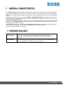
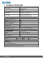
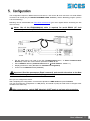
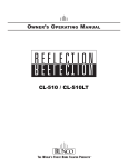
1
Filename: EAAM037301EN.docx Rev. 01 Date: 07/05/2013 ID Document: EAAM0373 Product: DANOUT (4 analog outputs module with RTU/CanBus Modbus protocol) ii 1. GENERAL CHARACTERISTICS .............................................................................. 3 1.1 VERSIONS AVAILABLE ....................................................................................... 3 2. TECHNICAL SPECIFICATION ................................................................................. 4 2.1 INDICATORS ....................................................................................................... 5 3. MODBUS SPECIFICATIONS .................................................................................... 5 4. CanBus specifications (EX-BUS proprietary SICES protocol)............................. 6 5. Configuration ........................................................................................................... 7 5.1 Select output type and end-of-scale ..................................................................... 8 5.2 Switch settings ...................................................................................................... 9 5.2.1 SWN Switch for MODBUS RS485 Version..................................................... 9 5.2.2 SWN switches for CanBus Version ................................................................ 9 5.2.3 JP serial configuration switch ....................................................................... 10 6. INSTALLATION INSTRUCTIONS ........................................................................... 10 7. Output connections ............................................................................................... 10 7.1 Current output ..................................................................................................... 10 7.1.1 Voltage output .............................................................................................. 10 8. Dimensions ............................................................................................................ 11 9. Summary of connections ...................................................................................... 12 9.1 CAN BUS version ............................................................................................... 12 9.2 RS485 version .................................................................................................... 12 User’s Manual The DANOUT (Digital Analogic Outputs) device generates voltage or current signals on four different channels, galvanically insulated either from each other and from power lines. Each channel can be independently configured, so to supply 0..5 V or 0..10 V voltage outputs or 0..10 or 0..20 mA current loops in active or passive mode. The device is available in two versions, with CANBUS or RS485 MODBUS RTU communication; both versions feature galvanically insulated communication lines. An additional (non insulated) RS232 Jack connection is available for device configuration. The outputs modulation is generally performed through a CANBUS (EX-BUS) connection with a dedicated protocol for a Sices DST4602 board. After setting the proper configuration parameters, the SICES board can manage up to 8 modules (32 outputs). The RS485 serial version is used for special applications, for sending direct commands from MODBUS RTU devices operating as masters, for working on the DANOUT device modbus registers. The device can be installed on a DIN guide. E6102094200xx E6102094201xx DANOUT CANBUS (insulated CAN BUS + non-insulated RS232 via jack connector). Designed to be used with DST4602 devices with CANBUS connection; up to 8 modules with SICES EX-BUS proprietary protocol can be connected DANOUT MODBUS RS485 (Insulated RS485 + non-insulated RS232 with jack connector used only for configuration). For use with devices using MODBUS RTU protocol with RS485 connection: 32 possible addresses. User’s Manual 3 Power voltage 7÷32VDC Typ. 280 mA (@ 13V) Max 380 mA (@ 13V) Typ. 3.7 W Max. 4.9 W 1000 V monopolar; two scales: 0.. 5V - 0..10V minimum load impedance 20 kOhm monopolar; two scales: 0..10mA - 0..20mA maximum load impedance 500 kOhm Current absorbed Power consumption Isolation of input reading channels Voltage outputs Current outputs Readings Precision (with reference to f.s.) 0.05% Linearity 0.05% Thermal drift (with reference to f.s.) 0.01%/K Update time (CAN signal) 200 ms Digital conversion resolution 14 bit Reading resolution 1/256 Command resolution (on DST4601/PX) 1/10 (0.1%) Reading dynamics received 0 to 100 % with 8 decimal bits (1/256ths). Environmental conditions Operating temperature : from -20°C to +60°C Humidity: from 30 to 90% condensate-free Storage temperature: from -20°C to +70°C Degree of protection IP 20 Dimensions/Weight Dimensions: 101Hx35Lx119D Weight: Connections J1 VDC power supply J6, J7, J8, J9 analog signal outputs JP 3.5 mm RS232 jack for parameter configuration. J2 RS485 or CANBUS connection with galvanic insulation. 4 User’s Manual 165 g LED Description ON WORK Running LED (flashes to indicate the device is on) Indicates the state of the main communication interface. CANBUS version: blinking LED = no communication (bus Off or passive error), REMOTE LED On = active CAN communication (Active error). RS485 version: LED Off = no communication, LED on = communication active. Protocol : Rtu Modbus Two switch selectable baud rates : 9600 / 19200 Transmission parameters: N, 8, 1 fixed Modbus address selectable via SWN switch: 1-32 (RS485 version), 1-16 (CANBUS version) Please note : register writing is switch-protected (SWN-8=OFF active protection, write not possible). Modbus Registers - Input Register Format 30001 Analog output 1 point value 30002 Analog output 2 point value 14 bit 30003 Analog output 3 point value (ranging from 0 to 16383) 30004 Analog output 4 point value 8 high bits = power on start-up, 30011 SWN switch on start-up and current 8 low bits = current switch position. 0=OFF, 1=ON 0 = normal operation, 30019 Test Flag 30201 Presence of CANBUS interface 1 = interface present, 0 = not present 30202 CANBUS state 0 = Error Active, 1 = Error Passive, 2 = BusOff 1 = testing board User’s Manual 5 Modbus Registers - Holding Register Format 40001 Analog output 1 point value 40002 Analog output 2 point value 14 bit 40003 Analog output 3 point value (ranging from 0 to 16383) 40004 Analog output 4 point value 40011 Analog output 1 percentage value 40012 Analog output 2 percentage value high 8 bits = entire part (0 to 100%) 40013 Analog output 3 percentage value 40014 Analog output 4 percentage value low 8 bits = decimal part (in 256ths: 0.5 = 127) 40101 Analog output type 1 0= 0-10 mA 40102 Analog output type 2 1= 0-20 mA 40103 Analog output type 3 2= 0-5 V 40104 Analog output type 4 3= 0-10 V 16 bit : CAN speed: 250 kbit/s CAN settings: sample point at 75%, 11bit identifier (standard format) Messages transmitted EX-BUS: ID MIX L. data Description Data: contain the 4 analog outputs percentage values. 16 bit for each reading. Typical transmission frequency : 200 msec 0x520 – 0x52F MXDDANOUT 8 byte Ex-Bus size: high 8 bits = entire percentage value from 0 to 100. low 8 bits = decimal value in 256ths. E.g.: 0x1466 = 20.4% 0x420 – 0x42F MXSDANOUT 6 byte Diagnostics. It contains: board type, firmware revision, CAN error counters. Transmission frequency: 1 sec. Note: each module transmits with an ID. The ID selection is made with SWN switches 1-4 (EX-BUS ADDRESS). To change the EX-BUS address, after modification via switch, turn the DANOUT module Off, then On again. For further information on EX-BUS protocol, refer to EAAS0346xxxx specifications. 6 User’s Manual The configuration requires a RS232 serial connection to a PC via the JP Jack connector or a serial RS485 connection via the J2 (only for DANOUT MODBUS RS485 versions ) and the BoardPrg program (version 2.25 and following). BoardPrg can be downloaded from www.sices.eu/download (you must register before accessing the site reserved area) Notes: Use of the E090000000142 cable is required for serial RS232 (JP Jack connector) connection (RS232-E20931 module connection cable). Set the serial port to be used on the PC (Communication Menu, Select Communication Resource). Check the communication parameters: 9600, N, 8, 1 Set the Modbus address (Communications Menu Serial address : default = 1) Display parameters value (File Menu Parameters management) Connect to the DANOUT board (Connect). Important: Read the parameters (Read command), and transfer the values to the New Value column, where you can edit them (Copy command). Now you can configure the device. After completing the configuration: check that the dipswitch is SWE 8=ON and press Transmit. You may now save the configuration on a PC (Save), and reload it (Load) at a later time to configure other modules in the same way. After programming, switch SWE dipswitch 8 OFF again to activate write protection. User’s Manual 7 Switches SWA, SWB, SWC and SWD set the output type for each channel; the switches SWAA, SWBB, SWCC, SWDD set active or passive mode: SWA, B, C, D Output type 0..10 mA SWx1 SWx2 OFF OFF 0..20 mA ON OFF 0..5 V OFF ON 0..10 V ON ON SWAA, BB, CC, DD Mode SWxx PASSIVE PAS ACTIVE ACT Important: Ensure to set switches only with module power Off. In passive mode the output current loop requires external power. In active mode the output current loop is directly powered by the DANOUT module. In case the selected output is of voltage type (0..5V o 0..10V), ensure that the mode switch is set to 'ACTIVE'. After setting the switches, ensure to adjust the parameters set in the DANOUT module. The default output type is set to 0, corresponding to the 0..10 mA output. Selecting the output type from parameter is required for a correct device operation (it allows using calibration data pertaining to the selected output type). Select in the drop down menu under "Output type" of the BoardPrg program. 8 User’s Manual 5.2.1 SWN SWITCHES Description 1- 5 Assign modbus device address (from 1 to 32) with SW6 = ON 6 Modbus address block. ON = from switches 1-5, OFF=1 fixed 7 Not used 8 ON = enable parameter writing Modbus address allocation table 5 4 3 2 1 1 2 3 4 5 6 7 8 9 10 11 12 13 14 15 16 17 18 19 20 21 22 23 24 25 26 27 28 29 30 31 32 SWN DIPSWITCHES ON MODBUS ADDRESS x x x x x x x x x x x x x x x x x x x x x x x x x x x x x x x x x x x x x x x x x x x x x x x x x x x x x x x X x x x x x x x X x x x x x x x X x x x x x x x X 5.2.2 SWN SWITCHES Jack JP Modbus Modbus device address assigned ID EX-BUS from 1 to 16 (tx from 0x520 to 0x52F; (if SWN 6=ON) rx from 0x420 to 0x42F) Not used Modbus address block. ON = selected with switches 1-4, OFF = 1 fixed Not used ON = enable parameter writing EX-BUS address assignment table 4 3 2 1 1 2 3 4 5 6 7 8 9 10 11 12 13 14 15 16 EX-BUS ADDRESS O N 2 3 4 5 6 7 8 EX-BUS SWN DIPSWITCHE S 1 Description x x x x x x x x x x x x x x x x x x x x x x x x x x x x x x x x User’s Manual 9 5.2.3 SWP SWITCH 1 2 3 4 ON Enables the RS485 120 Ω line termination resistor Disable RS232/RS485 serial JP Configures JP as serial RS232 baud rate = 19,200 OFF Disables the RS485 120 Ω line termination resistor Enable RS232/RS485 serial JP Configures JP as serial RS485 baud rate = 9,600 The device is designed to be mounted on a DIN 46277 guide in upright position. It requires adequate ventilation to function properly. Avoid installing above and/or near devices that produce heat. For analog outputs connection ensure to use twisted cables only; in case you use a shielded cable, ensure to connect the shielding to a ground close to the input connectors. For an RS485 connection, use a shielded cable with a 120 ohm impedance; for CANBUS connection, use the appropriate cable, e.g. KELUKABEL 800571. RS485/CANBUS terminations: to minimize reflections, the first and last device in the RS485 or CANBUS network must have a termination resistor connected in parallel with the 120 ohm ½ W line. Active operation: 7.1.1 Active operation: 10 User’s Manual Passive operation: User’s Manual 11 12 User’s Manual This document is owned by SICES s.r.l.. All rights reserved. SICES s.r.l. reserves the right to modify this document without prior notice. SICES has made any effort to ensure that the information herein provide are correct; in any case SICES does not assume any liability for the use these information. The disclosure by any means of this document to third parties is not allowed. SSSTTTTTGHTY 1