1
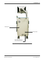
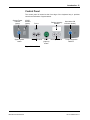
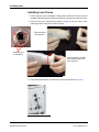
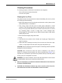
Ophthalmic Imaging System
Service Manual
PN 21-100357 Rev. A
2
Copyright
© 2008 Clarity Medical Systems, Inc. All rights reserved.
Trademarks
All other trademarks used in this document are the property of their respective
owners.
Clarity Medical Systems, Inc.
5775 W. Las Positas Blvd.
Pleasanton, CA 94588
USA
Phone: (925) 463-7984
Fax:
(925) 474-2093
Toll free:(800) 215-6005
www.claritymsi.com
www.retcam.com
[email protected]
MediMark® Europe S.A.R.L.
11 rue Emile Zola
38100 GRENOBLE
France
Tel: +33 (0)4 76 86 43 22
Fax: +33 (0)4 76 17 19 82
e-mail: [email protected]
RetCam3 Service Manual
PN 21-100357 Rev. A
3
Contents
1 Notices and Labels ........................................................................ 7
• Indications for Use .....................................................................................................7
• Warnings and Cautions....................................................................................7
• Electrical Safety Information ............................................................................8
• Important User Safety Notices .......................................................................10
• Labels and Symbols.......................................................................................11
• Product Label ..........................................................................................................14
2 Introduction.................................................................................. 15
• Storage and Transport ...................................................................................15
• System Description ........................................................................................16
• Control Panel .................................................................................................21
3 Maintenance ................................................................................ 23
• Recommended Maintenance Schedule .........................................................23
• Installing Lens Pieces ....................................................................................24
• Cleaning Procedures .....................................................................................25
• Cleaning the Lens Piece ..........................................................................................25
• Cleaning the Rest of the System .............................................................................26
• Disposal of Materials................................................................................................26
• Fluorescein Angiography Frequently Asked Questions .................................35
• Camera Color Balance Adjustment................................................................36
• Automatic Black Balance (ABB)...............................................................................37
• Automatic White Balance (AWB) .............................................................................38
• Lamp Replacement........................................................................................40
• Fuse Replacement.........................................................................................43
• Key Validation ................................................................................................45
• Servicing the Interior of the Cart ....................................................................47
4 Technical Specifications............................................................... 49
• Hardware .......................................................................................................49
•
•
•
•
•
•
•
Physical....................................................................................................................49
Electrical ..................................................................................................................49
Cart Features ...........................................................................................................49
Handheld Imager .....................................................................................................50
Computer and Electro-optics ...................................................................................50
Fluorescein Angiography Light Source (Optional) ...................................................50
Color Printer .............................................................................................................50
• Software.........................................................................................................50
• Environmental Conditions ........................................................................................51
5 Troubleshooting Guide ................................................................ 53
6 Block Diagrams ........................................................................... 59
• RetCam 3 Internal Wiring...............................................................................59
7 Replacement Parts ...................................................................... 61
• Customer Service Contact Information ....................................................................61
RetCam3 Service Manual
PN 21-100357 Rev. A
4
• Consumables .................................................................................................61
• Components...................................................................................................61
8 Technical Support ........................................................................ 63
• How to Get Support .......................................................................................63
• Support Within the US ...................................................................................63
•
•
•
•
•
Telephone Support ...................................................................................................63
FAX Support.............................................................................................................63
Write to Clarity..........................................................................................................63
E-mail Support .........................................................................................................64
Returning Parts for Repair .......................................................................................64
9 License Agreements.................................................................... 65
• CMS Software Restricted Rights ...................................................................65
• RetCam3 Software End User License Agreement.........................................65
10 Appendix Guide ........................................................................... 69
Appendix 1................................................................................... 71
• RetCam 3 Handpiece Replacement ..............................................................71
RetCam3 Service Manual
PN 21-100357 Rev. A
5
List of Figures
Figure 1
RetCam 3 Ophthalmic Imaging System Front View* .............................................. 18
Figure 2
RetCam 3 Ophthalmic Imaging System Rear View ................................................ 19
Figure 3
Handpiece and Lens Piece..................................................................................... 20
Figure 4
Lens Piece Selection .............................................................................................. 20
Figure 5
Control Panel .......................................................................................................... 21
Figure 6
Installing a lens piece on the handpiece................................................................. 24
Figure 7
Handpiece connections .......................................................................................... 24
Figure 8
Inverted lens piece showing permissible depth of immersion................................. 26
Figure 9
Removing the front panel ....................................................................................... 36
Figure 10
Automatic black balance test button ....................................................................... 37
Figure 11
Automatic white balance test button ....................................................................... 38
Figure 12
Light box cover removed ........................................................................................ 40
Figure 13
Front panel showing the lamp assembly drawer .................................................... 41
Figure 14
Removing the illumination lamp.............................................................................. 41
Figure 15
Power Entry Module ............................................................................................... 43
Figure 16
Opening the fuse holder cover ............................................................................... 43
Figure 17
Removing the fuse holder....................................................................................... 44
Figure 18
Fuses removed ....................................................................................................... 44
Figure 19
Fuse holder re-inserted .......................................................................................... 45
Figure 20
Key Validation dialog .............................................................................................. 46
Figure 21
Pull out the fiber optic cable ................................................................................... 72
Figure 22
Pull out the front cover............................................................................................ 73
Figure 23
Removing the cabling ............................................................................................. 73
Figure 24
Remove handpiece from box.................................................................................. 74
Figure 25
Threading cables through the front cover ............................................................... 74
Figure 26
Cable connections .................................................................................................. 75
Figure 27
Install front cover and fiber optic cable ................................................................... 75
Figure 28
Place handpiece in shipping box ............................................................................ 76
RetCam3 Service Manual
PN 21-100357 Rev. A
6
RetCam3 Service Manual
PN 21-100357 Rev. A
Notices and Labels 7
1 Notices and Labels
The RetCam3 Ophthalmic Imaging System (system) is designed to allow the
quick and easy capture of wide field, high resolution, fully digital images and videos
of the eye.
Indications for Use
For general ophthalmic imaging, including retinal, corneal, and external.
Warnings and Cautions
CAUTION: Federal law (US) restricts this device to sale by or on the order of a
physician or licensed medical practitioner.
WARNING: Prior to using the system, read all user safety information.
WARNING: Before using this equipment to acquire images from patient eyes, users
must be trained in proper clinical technique by personnel authorized by Clarity.
WARNING: The RetCam system is designed and tested as a system. Omission or
substitution of RetCam components may adversely affect system performance and
is strongly not recommended.
WARNING: Unauthorized modifications or additions to the RetCam system
(including hardware and software, etc.) could adversely affect system function and
will void the warranty.
WARNING: Carefully inspect and clean the lens piece before each use. DO NOT
USE if the lens piece has nicks, breaks, scratches, or rough surfaces that may
damage the eye.
WARNING: To mitigate the potential for excess light exposure, always start at the
lowest light intensity level and increase if necessary. Use only the shortest amount
of exposure time necessary; no greater than 5 minutes.
WARNING: Use care when contacting the eye; i.e., use the least amount of
pressure and/or movement necessary.
WARNING: A risk/benefit ratio must be assessed before confirming a patient for
RetCam
imaging
if
they
are:
photosensitive,
concomitantly
exposed
to
photosensitizing agents, or aphakic.
WARNING: To avoid the risk of electric shock, the equipment must be connected to
a supply mains with protective earth.
WARNING: To mitigate the potential for excess light exposure, the user should
avoid looking directly at the illuminated light source.
RetCam3 Service Manual
PN 21-100357 Rev. A
8 Notices and Labels
WARNING: There are high voltages within the FA module and the cover of the
module is not to be removed by customers or distributors.
Electrical Safety Information
The system has been designed, inspected and tested to comply with the safety
requirements of IEC60601-1 with respect to fire, shock and mechanical hazards
only if used as intended.
Class I Type BF Electrical Equipment
Rated for Continuous Operation
Electromagnetic Emissions
Compliance Level: Group 1, Class A
Test Type
Compliance Level
Conducted Emissions
CISPR 11/
EN 55011
Class A
Radiated Emissions
CISPR 11/
EN 55011
Class A
Harmonic emissions
IEC 61000-3-2
Complies
Voltage fluctuations/flicker emissions
IEC 61000-3-3
Complies
FCC Part 15B
Complies
RetCam3 Service Manual
Notes
The RetCam system uses RF energy for its internal
function. Nearby electronic equipment may be
affected.
PN 21-100357 Rev. A
Notices and Labels 9
Electromagnetic Immunity
Test Type
Electrostatic Discharge (ESD)
EN 61000-4-2
IEC 60601-1-2 test and
compliance level
±6 kV contact
±8 kV air
Floors should be wood, concrete or ceramic
tile. If floors are covered with synthetic
material, the relative humidity should be at
least 30%.
±2 kV for power supply lines
Mains power quality should be that of a typical
commercial or hospital environment. AC Power
electronic disturbances (transients) may cause
the system's display to scroll continuously. If
this occurs, imaging should not processed until
the disturbance has ceased.
±1 kV line(s) to line(s)
Mains power quality should be that of a typical
commercial or hospital environment.
Electrical Fast Transients
(AC Power)
(I/O Lines)
EN 61000-4-4
Surge Line to Line
(AC Power)
(I/O Lines)
EN 61000-4-5
Electromagnetic Environment Guidance
±2 kV line(s) to earth
>95% dip in Ut 0.5 cycle
60% dip in Ut 5 cycles
30% dip in Ut 25 cycles
>95% dip in Ut 5 seconds
If the user of the RetCam system requires
continued operation during power mains
interruptions, it is recommended that the
RetCam system be powered from an
uninterruptible power supply or a battery.
Power Frequency (50/60 Hz)
magnetic field
EN 61000-4-8
3 A/m
Power frequency magnetic fields should be at
levels characteristic of a typical location in a
typical commercial or hospital environment.
Radiated Immunity
EN 61000-4-3
80MHz-2.5GHz
3V/m 80%@1kHz
Portable and mobile RF communications
equipment should be used no closer to any
part of the RetCam system, including cables,
than the recommended separation distance
calculated from the equation applicable to the
frequency of the transmitter.
Voltage dips and interruptions
EN 61000-4-11
0.15-80MHz
3 Vrms 80%@1kHz
AC Mains
Recommended separation distance
d = 3.5 / E1
Conducted Immunity
EN 61000-4-6
P
80 MHz to 800 MHz
d = 7 / E1 P
800 MHz to 2.5 GHz
where P is the maximum output power rating of
the transmitter in watts (W) according to the
transmitter manufacturer and d is the
recommended separation distance in meters
(m). E1 is 3 V/m.
Conducted Immunity:
d= (3.5/ V1) P where V1 is 3 Vrms.
Field strength from fixed RF transmitters, as
determined by an electromagnetic site survey,
should be less than the compliance level in
each frequency range. Interference may occur
in the vicinity of equipment marked with the
following symbol.
RetCam3 Service Manual
PN 21-100357 Rev. A
10 Notices and Labels
WARNING: Interference may occur in the vicinity of
equipment marked with the following symbol.
This equipment/system may cause radio interference or may disrupt the operation
of nearby equipment. It may be necessary to take mitigation measures such as:
• Reorient or relocate the receiving device
• Increase the separation between the equipment
• Connect the equipment into an outlet on a circuit different from that to which the
other device(s) are connected.
• Consult the manufacturer or field service technician for help.
An error message may be displayed, which then may require a system reset. To
perform a system reset, press the system power switch on the control panel for ~6
seconds until the system powers down, wait 6 seconds, then press the switch again
to power the system back on.
WARNING: This equipment may cause radio interference or may disrupt the
operation of nearby equipment. It may be necessary to take mitigation measures,
such as reorienting or relocating the system or shielding the location.
WARNING: To avoid the risk of electric shock, this equipment must be connected to
a supply mains with protective earth.
WARNING: For continued protection against risk of fire, replace only with same
type and rating fuse.
Important User Safety Notices
1. Never contact the front of the lens piece with hard or sharp objects. This could
damage the precision optics and sealing.
2. DO NOT AUTOCLAVE any part of the device.
3. Appropriately power down and unplug the unit and allow the illumination lamp to
cool before replacing it.
4. Always return the handpiece to the holster when not imaging. You can drape the
handpiece cable over the cord wrap post on the side, but do not wrap it tightly or
damage to the fiber optic may result.
5. Do not block access to the holster.
6. The system is not intended to be transported outdoors.
7. Newly acquired data may be lost if power is interrupted during live imaging.
+
Note: backup battery power is available for at least 15 minutes after interrupt.
RetCam3 Service Manual
PN 21-100357 Rev. A
Notices and Labels 11
8. The system comes protected from viruses, worms, and spyware with Microsoft’s
anti-malware. Please refer to your warranty prior to adding any additional
software or contact Clarity Service.
Labels and Symbols
System Power Switch
Focus
Focus Controls
Lamp Illumination
Intensity Controls
SNAP (capture) switch
Read instructions
Caution:
Do not look directly into light source
Caution: Electrical hazard
High voltage in the FA unit
Chassis ground
Protective earth (ground)
RetCam3 Service Manual
PN 21-100357 Rev. A
12 Notices and Labels
Alternating current (AC)
System contains 2 fuses of indicated type.
Do not use any other type.
Backup battery
Computer network
Non-ionizing electromagnetic radiation
FA = Fluorescein Angiography
FA Intensity, increase clockwise
FA light OFF
FA light ON
Light source (fiber optic) connector
Handpiece connector
USB connector
RetCam3 Service Manual
PN 21-100357 Rev. A
Notices and Labels 13
Read accompanying user documentation
Fragile contents
This side of carton up
Temperature limits
Authorized representative in the EU
Type BF equipment (applied part is handpiece)
To prevent damage to lens piece, carefully store
handpiece in holster when not in use.
Clean lens piece after use
Separate collection of waste at end-of-life as required by
European directives. Contact Clarity for equipment
disposal instructions.
European conformity
North American compliance certification
Serial number
RetCam3 Service Manual
PN 21-100357 Rev. A
14 Notices and Labels
Date of Manufacture
Keep away from rain
Product Label
RetCam3 Service Manual
PN 21-100357 Rev. A
Introduction 15
2 Introduction
The RetCam 3 Wide Field Imaging System (system) is designed using
state-of-the-art digital technology to allow the quick and easy capture of wide field,
high resolution, fully digital images and videos of the eye.
The system is designed for easy use and operation by either a physician or trained
staff members. High resolution digital images and videos can be quickly captured,
stored, displayed for review, transferred and/or printed by simply using the mouse to
point and click.
The system as delivered is intended for use indoors, at normal room temperatures
(50º F to 95º F or 10º C to 35º C), non-condensing humidity range 30% to 90%,
upright, on a level surface, with the front casters locked.
This manual contains maintenance instructions, specifications and service
instructions.
+
Only those modules identified within this service manual are “authorized” for
replacement by the customer. Any service outside the scope of this manual
shall void the warranty and may compromise the safety/efficacy of the
system.
This manual is meant to be used in conjunction with the RetCam 3 User’s Manual.
The supplier will make available on request, component part lists, descriptions, or
other information which will assist the user's appropriately qualified technical
personnel to replace those parts of the equipment which are designated by the
manufacturer as replaceable.
CAUTION: Use of this manual is intended for qualified technical personnel only. If in
doubt, please contact the manufacturer before proceeding.
Storage and Transport
+
Note: Always return the handpiece to the holster on the top surface when not
imaging. The handpiece cable can be draped over the side cord wrap post,
but do not wrap it tightly or damage to the fiber optic may result.
For storage of the system when not in use, disconnect the power cord and store it in
one of the drawers. Remove all loose objects from the top surface. Wipe down the
surfaces with a soft cloth. Lock the casters.
The system can be easily moved between operations or between beds in the NICU
while it is running. To relocate the system while it is running, disconnect the power
cord at both ends, release the front caster locks and gently roll the system to the
new location. The internal batteries will keep the computer and monitor running for
several minutes. Once in the new position, lock the casters, reconnect the power
RetCam3 Service Manual
PN 21-100357 Rev. A
16 Introduction
cord at both ends and continue with imaging. If the floor is uneven, move the system
carefully to avoid damage from excessive vibration.
The system is not intended to be transported outdoors from building to building. For
information on how to safely transport the system out of doors or in anything but an
upright position, please contact Customer Service. The RetCam 3 has been
designed, inspected and tested to comply with the safety requirements of
IEC60601-1 with respect to fire, shock and mechanical hazards only if used as
intended. Inspection and testing of the system by a factory-trained technician after
transport outdoors or in a non-upright configuration is necessary to insure continued
compliance with all safety standards.
System Description
The RetCam 3 system consists of several modules mounted in a stable, high quality
integrated mobile cart for easy, safe transportation from one location to another. The
front pair of lockable casters allow for easy maneuverability and positioning. (See
Figure 1 on page 18).
• Display: A high resolution LCD flat panel display is standard with the system.
• Control Panel: A control panel turns the system on with one button, and has
controls for illumination intensity, camera focus and snap (capture an image or
start/stop video recording).
• Handpiece: The handpiece contains a 3-chip CCD. It is light weight and easy to
use. The front lens pieces are removable, and allow quick and easy exchange.
• Interconnect Cable: The interconnect harness contains three separate cables,
the fiber optic cable for transmission of illumination light, the camera cable, and
the focus motor control cable.
• Power Supply Box: The power supply box contains the input power converter,
power to charge the battery backup, power for the computer, camera controller
and the electro/optic circuits.
• CEO Box: (Computer Electro/Optical Box) The computer is a Pentium based
system, running a specialized Embedded Windows XP, with an external DVD
drive and proprietary software. The system has an integrated network adapter,
and USB hub. The Electro/Optical box contains a CCD camera control unit, a
halogen illumination lamp, and the control circuitry for light intensity, focus,
image capture and system logic.
RetCam3 Service Manual
PN 21-100357 Rev. A
Introduction 17
• Battery Backup: The battery backup helps to protect against accidental loss of
images due to sudden power loss. The battery backup can store enough energy
to power the computer and display for several minutes allowing the system to be
unplugged from the electrical outlet and moved from room to room or bed to bed
without having to reboot the system.
• Footswitch: The footswitch is a rocker style unit with a function switch on each
side, and a push button in the middle.
The pedal on the left side controls focusing. Rock this pedal to the left to focus
closer, and to the right to focus more distant.
The pedal on the right controls illumination light intensity. Rock this pedal to the
left to decrease intensity and to the right to increase intensity.
The push button in the middle is called the snap switch. An image is captured
and stored each time the snap switch is depressed. In video mode, this switch
can be used to alternately start and stop video recording.
• Storage Drawers: Two storage drawers are supplied on the system for
lenspieces and accessories. The upper drawer contains a mounted external
DVD drive.
• Image and Report Printer: A high resolution inkjet printer can print images
using 5” x 7” photo paper or reports on 8.5” x 11” paper.
• Fluorescein Angiography Source (optional): A blue exciter light source is
available complete with green barrier filter for the handpiece for doing
Fluorescein Angiography (F.A.) digital photography with the RetCam 3.
RetCam3 Service Manual
PN 21-100357 Rev. A
18 Introduction
Display
(contains 4 USB ports)
Transport
Handle
Handpiece with
Interchangeable
Lens Piece
Input Shelf
(extended)
Holster
Keyboard & Mouse
Control
Panel
DVD writer
(inside drawer)
USB port
Handpiece Cable
with Connectors
FA Intensity Control
Cord Wrap Post
(both sides)
FA Light Connector
FA Light Switch
Storage
Drawers
Printer on
Extended Shelf
Lockable
Front Casters
Footswitch
Storage Pocket
Footswitch
Figure 1 RetCam 3 Ophthalmic Imaging System Front View*
*Shown with optional FA (Fluorescein Angiography) feature
RetCam3 Service Manual
PN 21-100357 Rev. A
Introduction 19
Ethernet Port
Product Label
Main Power Switch and
Power Cord Connection
Figure 2 RetCam 3 Ophthalmic Imaging System Rear View
RetCam3 Service Manual
PN 21-100357 Rev. A
20 Introduction
Handpiece
Lens piece
Figure 3 Handpiece and Lens Piece
High Magnification
High Contrast
Children’s and
Adults
Portrait Lens
Standard Baby
Premature Infant
Figure 4 Lens Piece Selection
Lens Model
D1300
B1200
E800
C300
PL200
RetCam3 Service Manual
Application
Premature Infant
Standard Baby
High Contrast Children’s & Adults
High Magnification
Portrait Lens
Common Field of View
130 Degrees
120 Degrees
80 Degrees
30 Degrees
N/A
PN 21-100357 Rev. A
Introduction 21
Control Panel
The control panel is located at the front edge of the keyboard tray. It provides
controls and indicators of system status.
System Power
indicator
(green)
System power
button
AC/DC
indicator
(green)
Focus
Focus Controls
Relative intensity
indicator
Intensity Controls
SNAP
(capture)
button
Illumination ON
indicator (amber)
Lamp Illumination
ON/OFF
Figure 5 Control Panel
RetCam3 Service Manual
PN 21-100357 Rev. A
22 Introduction
RetCam3 Service Manual
PN 21-100357 Rev. A
Maintenance 23
3 Maintenance
This section addresses maintenance and support under the following topics:
• Recommended Maintenance Schedule, below
• Installing Lens Pieces, page 24
• Cleaning Procedures, page 25
• Camera Color Balance Adjustment, page 36
• Lamp Replacement, page 40
• Fuse Replacement, page 43
• Key Validation, page 45
• Servicing the Interior of the Cart, page 47
Recommended Maintenance Schedule
Between patients: Clean and inspect lens piece.
Weekly: Wipe down the system.
Monthly: Inspect cables and connections for wear.
System powered for at least 8 hours (AC powered - AC/DC indicator ON
light solid) to assure backup battery is fully charged.
Burned out bulb: Replace illumination bulb.
Blown fuse: Replace system fuses.
RetCam3 Service Manual
PN 21-100357 Rev. A
24 Maintenance
Installing Lens Pieces
1. Fit the lens piece on the handpiece, aligning the 3 radial pins on the front of the
handpiece with the spaces between the tabs of the spring ring on the lens piece.
2. Twist the lens piece clockwise (as shown in Figure 6) until you hear a click,
indicating that the lens piece is locked in place.
Align lens piece
to fit over pins
alignment pins
on handpiece
Carefully tighten clockwise
until it clicks in place. Do
not overtorque.
Figure 6 Installing a lens piece on the handpiece
3. Verify that the handpiece is connected to the system as shown in Figure 7.
Figure 7 Handpiece connections
RetCam3 Service Manual
PN 21-100357 Rev. A
Maintenance 25
Cleaning Procedures
For cleaning purposes, the RetCam3 is divided into two categories:
• The Lens Piece that contacts the patient
• The rest of the system
Cleaning the Lens Piece
The patient contact area lens should be cleaned immediately after use to prevent
the coupling gel from hardening.
1. Wipe away debris from the front lens piece surface with a soft dry tissue, sterile
water soaked tissue, or combination.
2. Then, using a clean soft cloth (such as sterile gauze) saturated in a fresh
solution of 70% IPA (isopropyl alcohol), gently wipe the front of the lens piece,
being sure to pay special attention to the concave contact lens area, to remove
any remaining debris; at least 11 wipes with a clean saturated cloth.
Pre-packaged 70% IPA swabs (such as ReliOn Alcohol swabs or BD Alcohol
Swabs) may be used.
3. Rinse surface thoroughly using sterile water.
4. Air dry.
5. Verify that the lens surface is free of debris and coupling gel. Repeat above
steps if necessary.
6. Inspect the lens for damage and clarity. Do not use the lens if there are chips,
cracks, or rough edges on the lens which may injure the patient’s eye.
CAUTION: Do not autoclave any part of the system. Autoclaving causes irreparable
damage and voids the warranty.
CAUTION: Never immerse the entire lens piece or handpiece in any liquid or
solution. If necessary, only the distal 4 mm can be immersed. See Figure 8. It is
important not to immerse the joint where the polished metal tip meets the painted
housing, since it is susceptible to corrosion.
WARNING: If you clean or disinfect, rinse the lens with sterile water to avoid corneal
de-epithelialization that may be caused by residual solution.
+
Note: For disinfection, see attached Information Statement from the American
+
CAUTION: As disinfection solutions may cause corrosion of the lens piece,
RetCam3 Service Manual
PN 21-100357 Rev. A
Academy of Ophthalmology.
soak times that exceed the recommendation should be avoided.
26 Maintenance
4 mm (0.16”)
Figure 8 Inverted lens piece showing permissible depth of immersion
Cleaning the Rest of the System
As with any medical device, use good public health practices when handling the
equipment, based on CDC guidelines. In addition, as with typical office equipment,
a gentle wiping with a cloth moistened with mild soap and/or water is
recommended. Do not spray cleaning solutions on any part of the system.
Disposal of Materials
Dispose of waste materials according to local and national requirements. Contact
Clarity Service if additional assistance is required.
RetCam3 Service Manual
PN 21-100357 Rev. A
Maintenance 27
RetCam3 Service Manual
PN 21-100357 Rev. A
28 Maintenance
RetCam3 Service Manual
PN 21-100357 Rev. A
Maintenance 29
RetCam3 Service Manual
PN 21-100357 Rev. A
30 Maintenance
RetCam3 Service Manual
PN 21-100357 Rev. A
Maintenance 31
RetCam3 Service Manual
PN 21-100357 Rev. A
32 Maintenance
RetCam3 Service Manual
PN 21-100357 Rev. A
Maintenance 33
RetCam3 Service Manual
PN 21-100357 Rev. A
34 Maintenance
RetCam3 Service Manual
PN 21-100357 Rev. A
Maintenance 35
Fluorescein Angiography Frequently Asked
Questions
WARNING: There are high voltages within the FA module and the cover of the
module is not to be removed by customers or distributors.
Q: Can the FA Light Source generate other colors and wavelengths of light?
A: No, it is designed for 471 nanometer blue excitation exclusively.
Q: How long does the Xenon bulb last?
A: The bulb is a special order and extensive testing data does not exist. However, a
guideline is that the intensity may reduce to one half the original value after 50 hours
of use, and then continue to reduce slowly after that. Some users have been
performing successful FA imaging up to 200 hours of lamp time.
Q: Can the bulb be replaced in the field?
A: It is not designed for field replacement. Return the unit to the factory if the output
is reduced or the lamp will not illuminate. Call Customer Service for assistance.
Q: How much does a replacement bulb cost?
A: It depends on the circumstances and what else is out of specification at the time
of service. You will be quoted the costs for repair of your FA Light Box before any
work is begun.
Q: Can I get a replacement barrier filter if mine is lost or broken?
A: Yes, contact Customer Service for a quotation.
Q: Can the FA Light Source be returned for service without returning the whole
RetCam 3?
A: Yes, the FA Light Source is a module that is removable by a person with the skill
level of a nominal biomedical technician. Be sure to package it as a sensitive
medical instrument with at least 3” of padding on all sides in a sturdy box, sealed
well, shipped insured for USD $20,000. NOTE: Clarity can send appropriate
packaging material to you if needed.
RetCam3 Service Manual
PN 21-100357 Rev. A
36 Maintenance
Camera Color Balance Adjustment
You must remove the front panel as illustrated below to access the color balance
buttons.
Pull from bottom outward and remove
Figure 9 Removing the front panel
+
When to Adjust Color Balance: Clarity Medical performs these procedures at
the factory before shipment. You should have to adjust the camera color
balance only rarely, and then only when the colors of the live image are very
different from the real object. If this occurs, we recommend you perform first
a black balance and then a white balance, in that order.
If you find that you must adjust the color balance frequently, please contact Clarity
Customer Service.
RetCam3 Service Manual
PN 21-100357 Rev. A
Maintenance 37
Automatic Black Balance (ABB)
The automatic black balance adjustment corrects the camera controller to display
black accurately. To adjust the automatic black balance, follow these steps:
1. With the system running, initiate a new imaging session and check on screen to
see that the camera is working (receiving an image).
+
Note: To start a new imaging session, you must select or create a patient
record.
2. Disconnect the fiber optic (lamp) cable. The handpiece should now not be
projecting any light.
3. Hold the front of the handpiece, with or without a front lens, against a towel or
soft cloth to block all light from entering the camera.
4. Press the ABB button on the front panel for about 1 second until characters
“ABB” appear and release button.
Figure 10 Automatic black balance test button
The characters “ABB” will stop blinking and the characters “ABB OK” will
appear for approximately 1 second. Black balance adjustment is successful.
If the characters “ABB NG” appear, it means that the automatic black balance
cannot be performed (NG = no good). Usually this is due to light leaking into the
black image. Try blocking ambient light more completely and press ABB again. If
the problem persists, please contact Clarity customer service.
RetCam3 Service Manual
PN 21-100357 Rev. A
38 Maintenance
Automatic White Balance (AWB)
The automatic white balance adjustment corrects the camera controller to display
colors accurately.
+
Note: This procedure should be done under room lighting that simulates
conditions during actual use.
To adjust the automatic white balance, follow these steps:
1. Perform automatic black balance as described above.
2. Reconnect the fiber optic (lamp) cable. The handpiece should now be projecting
light. Adjust the handpiece light level to that of normal usage.
3. Attach any front lens, if not already present. See Installing Lens Pieces on page
24.
4. Place a blank, white piece of paper on a flat surface. Hold the handpiece
perpendicular to the paper. Hold the tip of the lens approximately 2” (50 mm)
from the paper, so that the center of the image on the screen appears uniformly
bright. Adjust the light intensity on the control panel to read ~ 20 on the indicator
as a starting point. The outer area or ring of the image may be slightly gray or
yellow in color.
5. Press the AWB button on the front panel until the characters “AWB” appear on
the screen.
Figure 11 Automatic white balance test button
The characters “AWB” will stop blinking and the characters “AWB OK” will
appear for approximately 1 second. White balance adjustment is successful.
RetCam3 Service Manual
PN 21-100357 Rev. A
Maintenance 39
If the characters “AWB NG, LEVEL NG” appear, automatic white balance
adjustment cannot be performed because the light level is too high or too low.
Adjust the light level up or down as indicated and repeat steps 4. and 5. again. If
“AWB OK” still does not appear, try adjusting the ambient (room) lighting up or
down, or vary the distance from the front lens tip to the paper. If the problem
persists, please call customer service.
RetCam3 Service Manual
PN 21-100357 Rev. A
40 Maintenance
Lamp Replacement
WARNING: Appropriately power down and unplug the unit and allow the
illumination lamp to cool before replacing it.
Replacement illumination lamps are available from Clarity.
Follow these steps to replace the illumination lamp:
1. If it is not already turned OFF, turn OFF the instrument.
2. Disconnect the main power cord from the wall.
3. Unplug the fiber optic cable from the front panel.
4. Remove the light box cover.
Figure 12 Light box cover removed
RetCam3 Service Manual
PN 21-100357 Rev. A
Maintenance 41
5. Remove the two screws from the lamp assembly drawer, the smaller panel with
the black handle on the front.
Remove 2 screws
Lamp assembly
drawer
Lamp assembly
drawer handle
Figure 13 Front panel showing the lamp assembly drawer
6. Grip the handle on the lamp assembly drawer. Pull the drawer out slowly. Stop
when the light bulb is fully exposed.
7. Just behind the socket and extending from the rear of the illumination lamp is a
thick gray wire, the “lamp ejector” indicated in the picture below. Be prepared to
grab or catch the illumination lamp unit as you gently rotate this wire toward you
(rotate it up, or counterclockwise), which ejects the lamp. Remove the old
illumination lamp.
Lamp ejector
Figure 14 Removing the illumination lamp
RetCam3 Service Manual
PN 21-100357 Rev. A
42 Maintenance
CAUTION: Only touch the exterior surface of the illumination lamp. Do not touch the
bulb, which is located in the center of the reflector, nor the inner (concave) surface
of the reflector. Skin oils will adhere to the bulb and reflector, which reduces the
cooling efficiency of the bulb and thereby creates a hot-spot leading to premature
burnout. Handle by the outside of the lamp only, as shown.
8. Holding the new lamp only on the outside, as shown, replace it in the
assembly, aligning the two pins in the rear with the corresponding tracks in the
socket and pushing it gently and evenly into place.
9. Check the position of the new bulb to make sure that the reflector of the bulb is
located in the center of the lamp socket’s opening.
10.Push the lamp assembly drawer back in carefully. Use caution to avoid pinching
wires in the area.
11. Replace the two screws on the small front panel.
RetCam3 Service Manual
PN 21-100357 Rev. A
Maintenance 43
Fuse Replacement
Locate the power entry module on the lower right side of the rear of the cart. Make
sure to remove the power cord before proceeding any further. (See Figure 15.)
Figure 15 Power Entry Module
Using a flat blade screwdriver, gently pry open the cover of the fuse holder at the top
of the power entry module. (See Figure 16.)
Figure 16 Opening the fuse holder cover
RetCam3 Service Manual
PN 21-100357 Rev. A
44 Maintenance
Remove the fuse holder. (See Figure 17.)
Figure 17 Removing the fuse holder
Remove the blown fuse or fuses from the fuse holder and replace it with a new fuse
of same type and rating. (See Figure 18.) Re-insert the fuse holder.
Figure 18 Fuses removed
CAUTION: For continued protection against risk of fire, replace only with same type
and rating fuse.
Replacement fuses are available from Clarity Customer Service.
RetCam3 Service Manual
PN 21-100357 Rev. A
Maintenance 45
.
Figure 19 Fuse holder re-inserted
Key Validation
+
Note: New RetCam3 systems ship with their license key already registered
and validated. However, significant changes to the system hardware or a
re-load of the system software for any reason (including software upgrade)
may require you to perform the key validation process as described below.
Key validation requires that you get a license key from Clarity to use the
revamped system, and you cannot request this key until after installation is
complete. Since it may take up to two (2) business days to obtain a license
key after submitting a request, we recommend that you effect system or
software upgrades when you can manage two business days without use of
the system.
+
Note: To ensure the preservation of your patient data and images, we strongly
recommend that you perform a complete backup of the system’s images
before you begin any software installation.
RetCam3 Service Manual
PN 21-100357 Rev. A
46 Maintenance
When key validation is necessary, the Key Validation dialog appears when you start
the system (and each time thereafter until you complete this step), before the Site
Awareness dialog.
Figure 20 Key Validation dialog
Follow the instructions on screen: Call Clarity and provide to the customer support
representative the large license number in the dialog (71339298 in the example
above), which is unique for your system. You will be provided in turn a unique
authorization key.
0
Tip: You may also send the license number via email to [email protected]
and receive the authorization key by return email.
You must enter the authorization key in the field and click Validate Key to access
the system software. If you call, to make sure you enter the number correctly, we
recommend you do not hang up until the number is accepted.
RetCam3 Service Manual
PN 21-100357 Rev. A
Maintenance 47
Servicing the Interior of the Cart
WARNING: Removing the back panel should be done by qualified technical
personnel only.
Maintenance personnel should be familiar with the usual
precautions regarding the service of electronic and electrical equipment.
Contact Technical Service for help troubleshooting problems to the module level.
If it is determined that a module needs to be replaced, guidance from Technical
Service will be given in the form of a written procedure or verbal instruction. No
repairs are to be performed by the customer within the modules with the exception
of the lamp within the CEO box, as stated in the contents.
The modules comprising this system are:
• Display
• Handpiece
• Lens piece
• CEO box
• FA (option)
• Power Supply box
• Footswitch
• Batteries
WARNING: When doing this level of service, Electrical Safety Retesting of the
system is required to maintain compliance with IEC requirements. Contact
Customer Service before beginning.
+
Only those modules identified within this service manual are “authorized” for
replacement by the customer. Any service outside the scope of this manual
shall void the warranty and may compromise the safety/efficacy of the
system.
RetCam3 Service Manual
PN 21-100357 Rev. A
48 Maintenance
RetCam3 Service Manual
PN 21-100357 Rev. A
Technical Specifications 49
4 Technical Specifications
Hardware
Physical
• 26”(660 mm) wide x 24”(610 mm) deep x 54”(1372 mm) minimum height
• Approximately 200 lbs. (91 Kg) fully loaded
Electrical
• Ratings: 100-240 V~, 50/60 Hz, 700 VA
• Fuses: 3AG 10A 250V slo-blo 5 x 20 mm
• Power consumption: 700W with all options
• Detachable hospital grade power cord
Cart Features
The RetCam 3 cart includes the following features:
• System has been designed, inspected and tested to comply with the safety
requirements of IEC60601-1
• Internal Battery Backup
• Multi function Control Panel
• Tri-function footswitch
• Waterproof Keyboard
• Mouse
• LCD flat panel display
• Display arm for angle and height adjustment
• Handpiece cable hanger
• Integrated cooling ducts
• Dual Front locking castors
• Upper Storage drawer within which is mounted external DVD drive
• Lower Storage drawer with lenspiece holders
• Color report and image printer on slide out tray.
• USB ports
• Ethernet port
RetCam3 Service Manual
PN 21-100357 Rev. A
50 Technical Specifications
Handheld Imager
• 3-chip RGB CCD
• Built in fiber optics
• Quick-change lenspieces
Computer and Electro-optics
• Adjustable intensity iris
• Automatic black and white balance functions
• Lemo focus motor connector
• Custom fiber optic interlock
• Easy-access bulb replacement
• Embedded Computer
• 2.16 GHz Intel Processor
• 2 GB memory
• Hard drive storage
Fluorescein Angiography Light Source (Optional)
• Continuous arc xenon lamp
• Narrow-line blue excitation filter (~ 471 nm)
• Iris intensity control
• Fiber optic safety interlock
• Green emission (blocking) filter for handheld imager (~ 510 nm)
Color Printer
Software
• The software allows for networkability.
• MS Windows® XP Embedded operating system with service pack 2
• Proprietary image acquisition, storage and processing
• Live color image display
• Integrated patient database
• Still and video capture modes
• Review functions
• Compare functions
• Transfer functions
• Backup functions
• Image export as MLX, DICOM, or open standard, i.e. jpeg, bmp or png
RetCam3 Service Manual
PN 21-100357 Rev. A
Technical Specifications 51
• Image annotation
• Data export as XML, CSV or TXT
• Image import of RetCam supported files; .hdr, .mli, .mlv, .mlx, .mrl
• Fluorescein Angiography mode
Environmental Conditions
The system as delivered is intended for use indoors, at normal room temperatures
and humidity, upright, on a level surface, with the brakes applied to the front casters.
+
RetCam3 Service Manual
Condition
Operating
Storage and Transport
Temperature
50º to 95º F (10º to 35º C)
-20º to 122º F (-29º to 50º C)
Relative Humidity 30% to 90% non-condensing
10% to 85% non-condensing
Atmospheric
Pressure
20.7 to 31.3 inches Hg (70 to
106 kPa)
14.7 to 31.3 inches Hg (50 to
106 kPa)
Altitude
-1255 to 9882 feet (-382 to
3012 meters)
-1255 to 18288 feet (-382 to
5574 meters)
Note: Specifications subject to change without notice.
PN 21-100357 Rev. A
52 Technical Specifications
RetCam3 Service Manual
PN 21-100357 Rev. A
Troubleshooting Guide 53
5 Troubleshooting Guide
This section lists common issues for the RetCam3 Ophthalmic Imaging System
and provides suggested corrective actions for each issue. If corrective actions do
not resolve the issue, contact Clarity Technical Support at (800) 215-6005 or email
[email protected].
RetCam 3 Troubleshooting Guide
Issue
Troubleshooting Recommendations
No power to RetCam 3 system
Verify power cord is connected.
Verify power source is correct voltage for
system and is functioning correctly.
Verify the main power switch in the back
of the RetCam system turned on.
If the system has not been plugged into
the wall for at least 4 hours before the
intended use, plug the system in to let the
battery charge, then press the power
button on the control panel.
No display
The display will be dark initially while the
program is loading. If the display is still
dark after five minutes, verify that the
monitor is turned on.
Verify monitor power indicator light is on.
Verify monitor cable and power cord are
connected properly.
Verify monitor functionality;
• Connect monitor to alternate system.
• Connect alternate monitor to system.
No RetCam 3 program
Restart the system.
Verify RetCam splash screen displays.
Verify error messages displayed. Obtain
details.
If system is connected to network,
disconnect from network and restart the
system.
RetCam3 Service Manual
PN 21-100357 Rev. A
54 Troubleshooting Guide
RetCam 3 Troubleshooting Guide
Issue
Troubleshooting Recommendations
No camera image
Verify connections are secure.
Verify the hand-piece camera cable is
connected to the CEO box.
Verify the camera cable is connected
securely.
If there is still no image, contact the Clarity
service department at (800) 215-6005.
Unable to save image
Verify destination location of file to be
saved (local, USB, network, etc.)
Verify there is sufficient available space at
the destination location.
Observe any error messages displayed
while saving. Obtain details.
Unable to transfer an image
Check the file transfer destination
location. If networking the system, verify
settings and permissions.
Verify that the destination device or
network location is resident in RetCam
program.
Verify that the device is recognized in File
Explorer.
If network location is available and the file
transfer fails:
• Verify you have successful connectivity
to network Share directory.
• Verify you are successfully logged on to
your network.
• Verify network share file parameters.
Unable to print report or image file
Verify printer power indicator lights are on.
Verify printer cable connections are
properly connected.
Observe any printer error codes
displayed.
Verify printer media is properly installed.
RetCam3 Service Manual
PN 21-100357 Rev. A
Troubleshooting Guide 55
RetCam 3 Troubleshooting Guide
Issue
Troubleshooting Recommendations
No light from hand-piece
Verify the fiber optic cable from the
handpiece is inserted in the fiber optic port
of the CEO box and the lamp button on
the control panel is turned on.
Leave the lamp off for 10 minutes to allow
the lamp to cool down and then turn it
back on.
If after these measures are taken the lamp
does not turn on, then replace the
illumination bulb. See Lamp Replacement
on page 40.
Light intensity does not increase or
decrease
Press the light intensity button on the
control panel first, and then press the light
intensity pedal on the footswitch. Observe
the intensity of light coming out of the
handpiece. If the intensity does not
change with either action, contact
customer service.
Live image problem
If the color of the live image is not
balanced, perform the Automatic White
Balance procedure in the User or Service
manuals.
If there are color “streaks” in the live
image, the handpiece must be sent in for
service.
If live image freezes, start and stop video.
Image does not focus
Check the lenspiece for cleanliness. If
there is dried gel on the lenspiece, clean
off with sterile water.
Verify that the handpiece focus cable is
connected to the CEO box correctly.
When the focus button is pressed, listen
for the sound of the motor turning within
the handpiece.
Verify footswitch pedals are not jammed.
If you cannot hear the motor, contact
Clarity Medical Systems.
For further assistance please contact
Clarity Technical Support at (800)
215-6005 or email [email protected].
RetCam3 Service Manual
PN 21-100357 Rev. A
56 Troubleshooting Guide
RetCam 3 Troubleshooting Guide
Issue
Troubleshooting Recommendations
Image capture is not working
If you can capture a live image using the
software, verify that an image can also be
captured using the control panel button.
If you can capture an image using the
control panel button, then take an image
using the snap button on the footswitch.
If you can capture an image using the
snap button on the footswitch, but not
using the control panel, the control panel
must be replaced.
Contact Clarity Technical Support at (800)
215-6005 or email [email protected]
No numbers displayed on control panel If the system is turned on and the RetCam
for light intensity
program is displayed on the monitor but
no numbers appear on the control panel
for light intensity, then press the intensity
button to turn the lamp on.
RetCam3 Service Manual
USB stick is not recognized
Because the operating system of the
RetCam 3 is embedded, not all USB
sticks will be recognized. If the USB stick
is not recognized in the Utilities screen,
then use the USB stick provided by
Clarity.
Keyboard does not work
If repairs to the computer have been
performed recently, then verify the
keyboard cable is inserted into the
keyboard connection at the CEO box.
The system turns off when it is
unplugged and moved
This can happen when the battery is in a
low charge condition. The normal time a
system can be unplugged from the power
source with the program running can be
from 10 to 20 minutes on a fully charged
battery. It is best to leave the RetCam 3
plugged in when not in use so the battery
can charge.
PN 21-100357 Rev. A
Troubleshooting Guide 57
RetCam 3 Troubleshooting Guide
Issue
Troubleshooting Recommendations
No light from the FA
Verify that the fiber optic cable from the
handpiece is fully inserted in the fiber port
of the FA.
If no blue light can be seen while the light
switch on the front of the FA is turned on,
the module must be returned to the
factory for service.
Contact Clarity Technical Support at (800)
215-6005 or email [email protected].
RetCam3 Service Manual
No network connection
Contact your Information Technology (IT)
department.
The machine does not move freely.
Check the locks on the front wheels.
PN 21-100357 Rev. A
58 Troubleshooting Guide
RetCam3 Service Manual
PN 21-100357 Rev. A
Block Diagrams 59
RetCam 3 Internal Wiring
6 Block Diagrams
RetCam3 Service Manual
PN 21-100357 Rev. A
60 Block Diagrams
RetCam3 Service Manual
PN 21-100357 Rev. A
Replacement Parts 61
7 Replacement Parts
Spare parts and supplies can be ordered by calling or faxing the part description and
part number to Customer Service.
Customer Service Contact Information
Phone: (925) 463-7984
Fax:
(925) 474-2093
Toll free:(800) 215-6005
Consumables
Part Description
Part Number
Illumination Bulb (halogen)
02-04-501
USB STICK
03-12-025
Fuses - 3AG 10A/250V, slo blo, 5 x 15-000053
20 mm
Printer paper, HP Premium, 5 x 7
inches
03-12-012
Components
Part Description
Part Number
Flat Panel Display
21-100224
Footswitch
21-100200
Handpiece
21-100064
CEO box
21-100194
Portrait Lens (PL200)
18-000024
Premature Infant lens (130°)
01-00-015
Standard Baby lens (120°)
01-00-001-1
High Contrast lens (80°)
01-00-016
High Magnification lens (30°)
01-00-014-1
FA Barrier Filter
09-00-015
FA install Kit (order with a new FA) 21-100362
RetCam3 Service Manual
FA Lightbox
21-100225
Printer
21-100339
Mouse
21-100332
DVD writer drive
21-100338
PN 21-100357 Rev. A
62 Replacement Parts
RetCam3 Service Manual
PN 21-100357 Rev. A
Technical Support 63
8 Technical Support
How to Get Support
The User Manual and Service Manual have been written to answer the majority of
questions that arise with the product. Please consult these manuals before calling
for service.
Clarity Medical Systems, Inc.’s (CMS) in-house technical staff is dedicated to
helping our users with any specific problems and questions you may have with the
RetCam 3. Please have your serial number ready and include the serial number on
all correspondence. The serial number is located on a sticker affixed to the base of
the cart at the back just above the power cord connection.
Please be as specific and give as much information as possible. If you encounter a
system malfunction of any kind, please record the exact steps taken leading to the
failure, so that our staff can replicate the problem.
+
Customers in the rest of the world outside the US, please contact your
distributor.
Support Within the US
Telephone Support
Direct dial: (925) 463-7984
Toll Free: (800) 215-6005
FAX Support
(925) 474-2093
Telephone support is typically available between the hours of 9am and 5pm Pacific
Time.
Write to Clarity
You can send written requests to Clarity at the address below:
Clarity Medical Systems, Inc.
5775 West Las Positas Blvd.
Pleasanton, CA 94588
USA
RetCam3 Service Manual
PN 21-100357 Rev. A
64 Technical Support
E-mail Support
Send e-mail messages to customer support at the address below:
[email protected]
Our technical support staff responds to your questions as soon as a staff member is
available. In most cases, you will receive an answer within 48 hours. Complex
questions that require testing or special research may take longer.
+
Note: Questions about products no longer under warranty and questions
other than to explain ordinary use of the product may incur engineering
charges. Please ask for an hourly quotation before incurring charges.
Returning Parts for Repair
If a part or component is defective or damaged and is to be returned to Clarity
Medical Systems for repair or replacement, a Service Ticket number must be issued
by CMS. The Service Ticket number must be noted on the return shipping
documents so that the disposition of the part is known when it is received at CMS
offices.
RetCam3 Service Manual
PN 21-100357 Rev. A
License Agreements 65
9 License Agreements
CMS Software Restricted Rights
This Software and accompanying written materials are provided with Restricted
Rights. Use, duplication, or disclosure by the U.S. Government is subject to
restrictions applicable to commercial computer software (under FAR 52.227--19 and
DFARS 25.227-7013). Contractor/manufacturer is Clarity Medical Systems, Inc.
This Agreement is governed in and by the laws of the State of California, U.S.A.
This statement gives you specific legal rights; you may have others which vary from
state to state and from country to country. Clarity Medical Systems, Inc. reserves all
rights not specifically granted in this statement.
Any attempt to decompile, reverse engineer or otherwise copy this software shall be
considered a breach of this agreement.
RetCam3 Software End User License Agreement
You have acquired a RetCam3 (“DEVICE”) that includes software licensed by
Clarity Medical Systems, Inc. (“CMS, Inc.”) from Microsoft Licensing Inc. or its
affiliates (“MS”). Those installed software products of MS origin, as well as
associated media, printed materials, and “online” or electronic documentation
(“SOFTWARE”) are protected by international intellectual property laws and
treaties. The SOFTWARE is licensed, not sold. All rights reserved.
IF YOU DO NOT AGREE TO THIS END USER LICENSE AGREEMENT (“EULA”),
DO NOT USE THE DEVICE OR COPY THE SOFTWARE. INSTEAD, PROMPTLY
CONTACT CMS, INC. FOR INSTRUCTIONS ON RETURN OF THE UNUSED
DEVICE OR A REFUND. ANY USE OF THE SOFTWARE, INCLUDING BUT NOT
LIMITED TO USE ON THE DEVICE WILL CONSTITUTE YOUR AGREEMENT TO
THIS EULA (OR RATIFICATION OF ANY PREVIOUS CONSENT).
GRANT OF SOFTWARE LICENSE. This EULA grants you the following license:
• YOU MAY USE THE SOFTWARE ONLY ON THE DEVICE.
• NOT FAULT TOLERANT. THE SOFTWARE IS NOT FAULT TOLERANT. CMS,
INC. HAS INDEPENDENTLY DETERMINED HOW TO USE THE SOFTWARE
IN THE DEVICE, AND MS HAS RELIED UPON CMS, INC. TO CONDUCT
SUFFICIENT TESTING TO DETERMINE THAT THE SOFTWARE IS
SUITABLE FOR SUCH USE.
RetCam3 Service Manual
PN 21-100357 Rev. A
66 License Agreements
• WITH THE EXCEPTION OF THE LIMITED WARRANTY PROVIDED BY
CLARITY MEDICAL SYSTEMS, THE SOFTWARE IS PROVIDED “AS IS” AND
WITH ALL FAULTS. THE ENTIRE RISK AS TO SATISFACTORY QUALITY,
PERFORMANCE, ACCURACY, AND EFFORT (INCLUDING LACK OF
NEGLIGENCE) IS WITH YOU. ALSO, THERE IS NO WARRANTY AGAINST
INTERFERENCE WITH YOUR USE OF THE SOFTWARE OR AGAINST
INFRINGEMENT. IF YOU HAVE RECEIVED ANY WARRANTIES, OTHER
THAN THE LIMITED WARRANTY PROVIDED BY CLARITY MEDICAL
SYSTEMS, REGARDING THE DEVICE OR THE SOFTWARE, THOSE
WARRANTIES DO NOT ORIGINATE FROM, AND ARE NOT BINDING ON, MS
OR CMS.
• Note on Java support. The SOFTWARE may contain support for programs
written in Java. Java technology is not fault tolerant and is not designed,
manufactured, or intended for use or resale as online control equipment in
hazardous environments requiring fail-safe performance, such as in the
operating of nuclear facilities, aircraft navigation or communications systems, air
traffic control, direct life support machines, or weapons systems, in which the
failure of Java technology could lead directly to death, personal injury, or severe
physical or environmental damage. Sun Microsystems, Inc. has contractually
obligated MS to make this disclaimer.
• No Liability for Certain Damages. EXCEPT AS PROHIBITED BY LAW, MS
SHALL
HAVE
NO
LIABILITY
FOR
ANY
INDIRECT,
SPECIAL,
CONSEQUENTIAL OR INCIDENTAL DAMAGES ARISING FROM OR IN
CONNECTION WITH THE USE OR PERFORMANCE OF THE SOFTWARE.
THIS LIMITATION SHALL APPLY EVEN IF ANY REMEDY FAILS OF ITS
ESSENTIAL PURPOSE. IN NO EVENT SHALL MS BE LIABLE FOR ANY
AMOUNT IN EXCESS OF U.S. TWO HUNDRED FIFTY DOLLARS (U.S.
$250.00).
• Limitations on Reverse Engineering, Decompilation, and Disassembly. You may
not reverse engineer, decompile, or disassemble the SOFTWARE, except and
only to the extent that such activity is expressly permitted by applicable law
notwithstanding this limitation.
• SOFTWARE TRANSFER ALLOWED BUT WITH RESTRICTIONS. You may
permanently transfer rights under this EULA only as part of a permanent sale or
transfer of the DEVICE, and only if the recipient agrees to this EULA. If the
SOFTWARE is an upgrade, any transfer must also include all prior versions of
the SOFTWARE.
• EXPORT RESTRICTIONS. You acknowledge that SOFTWARE is subject to
U.S. export jurisdiction. You agree to comply with all applicable international and
national laws that apply to the SOFTWARE, including the U.S. Export
Administration Regulations, as well as end-use and destination restrictions
RetCam3 Service Manual
PN 21-100357 Rev. A
License Agreements 67
issued by U.S. and other governments. For additional information see
http://www.microsoft.com/exporting/.
RetCam3 Service Manual
PN 21-100357 Rev. A
68 License Agreements
RetCam3 Service Manual
PN 21-100357 Rev. A
Appendix Guide 69
10 Appendix Guide
Appendix Table
RetCam3 Service Manual
Appendix
Number
Procedure
Number
Revision
Document Title
1
30-000071
A
RetCam 3 Handpiece Replacement
PN 21-100357 Rev. A
70 Appendix Guide
RetCam3 Service Manual
PN 21-100357 Rev. A
Appendix 1 71
Appendix 1
Field Replacement Procedure 30-000071 Rev. A
RetCam 3 Handpiece Replacement
RetCam3 Service Manual
Rev
ECO
Revision
History
Author
A
3267
Release
Calvin Meister
PN 21-100357 Rev. A
72 Appendix 1
1.0 Purpose
1.1 To provide instructions on how to replace a Handpiece in a RetCam 3
System.
2.0 Scope
2.1 This procedure provides the step by step process to replace the Handpiece.
3.0 References
3.1 Plastic Housing Handpiece 21-100064
3.2 RetCam 3 Service Manual 21-100357
4.0 Equipment and Tooling
4.1 NA
5.0 Material and Supplies
5.1 NA
6.0 Handpiece Replacement Procedure
6.1 Remove the handpiece from the RetCam 3.
6.1.1 Power down the system according to the RetCam 3 User Manual.
6.1.2. Disconnect the system power cord from the base of the system.
6.1.3. Lock the front casters.
6.1.4. Pull out the fiber optic cable.
Figure 21 Pull out the fiber optic cable
6.1.5 Pull out the front cover.
RetCam3 Service Manual
PN 21-100357 Rev. A
Appendix 1 73
Camera
cable
Front cover being pulled out
Focus connection
Figure 22 Pull out the front cover
6.1.6 For focus connection insertion and removal be aware of the red
alignment dots on the connections. To remove the focus connector, pull
back on the metal connector sleeve.
6.1.7. To remove the camera cable from the CEO box, turn the metal sleeve
counterclockwise at least 5 turns and slowly pull out on the connector.
6.1.8. Remove the cabling from the front cover.
Figure 23 Removing the cabling
6.1.9. Carefully set aside the handpiece.
6.2 Install the replacement handpiece.
6.2.1. Remove the replacement handpiece from the box.
RetCam3 Service Manual
PN 21-100357 Rev. A
74 Appendix 1
Figure 24 Remove handpiece from box
6.2.2. Thread the handpiece focus and camera cables through the front
cover.
Figure 25 Threading cables through the front cover
6.2.3. To install the focus cable, align the red dots on the connectors and
insert the metal sleeve.
6.2.4. To install the camera cable, align the slot on the cable connector with
the pin (at the 6 o’clock position) in the port and insert. Then thread on the
sleeve of the connector clockwise until tight.
RetCam3 Service Manual
PN 21-100357 Rev. A
Appendix 1 75
6 o’clock
Camera connections
Focus connection
Figure 26 Cable connections
6.2.5. Install the front cover
6.2.6. Install the fiber optic cable
Figure 27 Install front cover and fiber optic cable
6.3. Verifying the handpiece works
6.3.1. Plug the RetCam 3 system in and turn it on.
6.3.2. Install a lenspiece on the handpiece.
6.3.3. Select a test patient and go to new exam.
6.3.4. View image for color balance.
6.3.5. If the colors of the live image are very different from the real object,
follow the Camera Color Balance Adjustment method in the Maintenance
section of the Service Manual. If the color balance is similar to the real
object then proceed to the next step.
6.4. Restore the System to original condition.
RetCam3 Service Manual
PN 21-100357 Rev. A
76 Appendix 1
6.4.1. When testing is complete and the system is not being used then press
the power button to turn off.
7.0 For the Handpiece to be returned to Clarity
7.1. Place the handpiece to be returned to Clarity in the box as shown.
Figure 28 Place handpiece in shipping box
7.2. Ship the handpiece to Clarity
RetCam3 Service Manual
PN 21-100357 Rev. A
5775 W. Las Positas Blvd.
Pleasanton, CA 94588
USA
Phone:
(925) 463-7984
Fax:
(925) 251-0078
Toll free:
1-800-215-6005
www.claritymsi.com
RetCam3 Service Manual
PN 21-100357 Rev. A