1
Spicer Single Drive Axles
®
Service Manual
Spicer® Single Drive Axles
AXSM-0041
September 2007
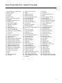
Table of Contents
Power Divider - Parts Exploded View........................ 23
Remove Power Divider ............................................. 24
Remove Power Divider from Differential Carrier
(with carrier removed from axle housing) ................ 25
Disassemble, Assemble and Overhaul
the Power Divider ..................................................... 27
Install Power Divider on Differential Carrier
(with carrier assembled to axle housing) .................. 38
Install Power Divider on Differential Carrier
(with carrier removed from axle housing) ................. 40
Dissasemble Differential Carrier
(with power divider removed) ................................... 54
Drive Pinion
Drive Pinion - Parts Exploded View ............................ 57
Disassemble and Overhaul Drive Pinion .................... 58
Install Drive Pinion Assembly.................................... 65
Wheel Differential Assembly
Wheel Differential Assembly
- Parts Exploded View ............................................... 68
Housing and Rear Cover Assembly
- Parts Exploded View ............................................... 91
Seals ..................................................................92
Housing Breather ..............................................94
Wheel End Seal - Parts Exploded View .............95
Remove and Overhaul Wheel End Seal .............96
Wheel Adjustment Systems ..............................97
Verify Wheel End-play Procedure ......................99
Lubricate Wheel End .......................................100
Lubrication ......................................................102
Lube Change Intervals ....................................103
Change Lube ...................................................104
Standpipes ......................................................105
Torque Chart ...................................................107
Appendix
Table of Contents
Introduction .........................................................1
Failure Analysis ...................................................7
Inspection ...........................................................9
Differential Carrier Assembly - Parts .................11
Differential Lockout ...........................................17
Power Divider
Wheel Differential Lock ...........................................109
Differential Lock Theory of Operation ....................110
Control Systems ....................................................111
Dual Range Axle Shift Systems ..............................113
Troubleshooting .....................................................120
Proper Vehicle Towing ...........................................122
Axle Shift System Components ..............................124
Inter-Axle Differential Lockout
With Interlock Control Valve (straight-air type) ......126
Theory of Operation ...............................................129
Power Flow and Torque Distribution ......................130
Lubrication .............................................................132
Torque Distribution in Low Range .........................136
i
Out of Vehicle Resetting
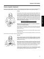
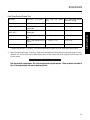
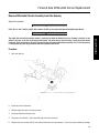
Introduction
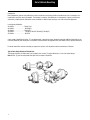
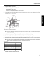
Dana Corporation, presents this publication to aid in maintenance and overhaul of Dana tandem drive axles. Instructions contained herein cover four basic axle models. Their design is common, with differences in load capacity. Capacity variations are
achieved by combining basic differential carrier assemblies in different axle housings, axle shafts and wheel equipment.
Load Capacity Model No.
34,000 lbs. . . . . . . . . . . . . .. DS340, 341
38,000 lbs. . . . . . . . . . . . . . . DS2380(P)
38,000 lbs. . . . . . . . . . . . . .. DS381(P)*
40,000 lbs. . . . . . . . . . . . . . . . DS400-P, DS401-P, DS402(P), DS403(P)
45,000 lbs.. . . . . . . . . . . . . .. DS451-P
Some models (identified with letter “P”) are equipped with a gear-driven pump, designed to provide additional lubrication to the
inter-axle differential and related parts. Instructions contained herein are applicable to all axle models, unless specified otherwise.
For brake information and axle mounting or suspension systems, refer to pertinent truck manufacturer’s literature.
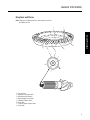
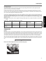
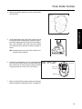
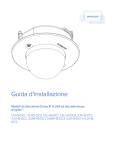
Typical Dana Single Reduction Tandem Axle
Two design variations of tandem axles are included in this manual. The major difference is in the shaft spline design.
Note: DS381 (P) axles manufactured after April 1985 are rated at 40,000 lbs.
1
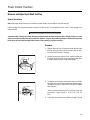
General Information
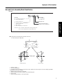
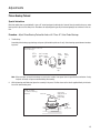
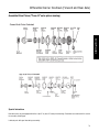
Axle and Carrier Assembly Model Identification
Drive Axle
Gearing
D - Forward Tandem Axle
R - Rear Tandem Axle
Lube Pump
P = Standard
(P) = Optional
S - Single Reduction
D - Single Reduction with Wheel
Differential Lock
T - Dual Range
P - Planetary Double Reduction
Design Level
Service Procedure
Capacity (x 1000 lbs.)
Example: 46 = 46,000 lbs.
Example: DS = Forward Tandem Axle/Single Reduction
RS = Rear Tandem Axle/Single Reduction
Note: Tags that do not include all the information shown here
are older models (before May 1987).
4
3
5
Spicer®
CUST. PART NO.
SPEC.
SERIAL NO.
2
MODEL PART NO.
1
®recipS
.ON TRAP .TSUC
.ON LAIRES
OITAR
.CEPS
.ON TRAP LEDOM
:NI EDAM
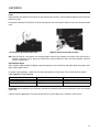
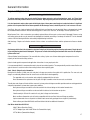
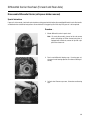
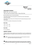
Forward Axle (Side View)
6
RATIO
MADE IN:
7
Data plate is located on
the axle centerline
Spicer®
CUST. PART NO.
SPEC.
MODEL PART NO.
SERIAL NO.
RATIO
MADE IN:
Rear Axle (Top View)
1 - Country or origin
2 - Axle model identification
3 - Specification number assigned to the axle built by Spicer. Identifies all component parts of the axle including special OEM
requirements such as yokes or flanges.
4 - OEM part number assigned to the axle build
5 - Carrier assembly serial number assigned by the manufacturing plant
6 - Axle gear ratio
7 - Carrier assembly production or service part number
2
General Information
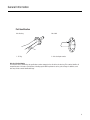
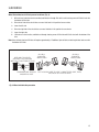
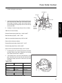
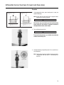
Part Identification
Axle Housing
Axle Shaft
2
®
cerS.
Spi LB
.
NO
PT. CAP.
O.
G.
HS I.D. N DE IN
A
G.
HS ING M
US
HO
1
1 - ID Tag
2 - Axle shaft part number
Axle Specification Number
The complete axle is identified by the specification number stamped on the side of the axle housing. This number identifies all
component parts of the axle as built by Dana, including special OEM requirements such as yoke or flange. In addition, some
axles may include a metal identification tage.
3
General Information
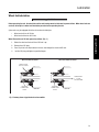
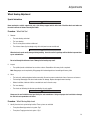
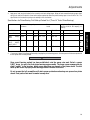
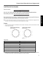
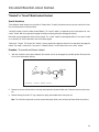
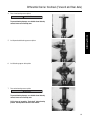
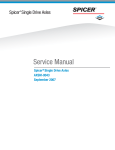
Ring Gear and Pinion
Note: Ring gear and drive pinion are matched parts and must
be replaced in sets.
3
8
Service Procedure
38
127381
SPICER
OF
NL2
41-8
1
17
G
L70
4
6
7
2
5
8
6
7
17
SPICER
0H
7
12
127
8-41
G
428
127
3
1
L7038
6-39
85405
JD77
86
TO
N
EA
4
1 - Part number
2 - Number of ring gear teeth
3 - Manufacturing numbers
4 - Matching gear set number
5 - Number of pinion teeth
6 - Date code
7 - Indicates genuine Spicer parts
8 - Heat code
4
General Information
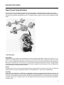
Power Flow and Torque Distribution
Spicer tandem drive axles described in this publication are single reduction units designed primarily for highway or turnpike.
They are also for a variety of other applications. This type of axle provides a vehicle with superior load carrying and roadability
characteristics by dividing its work between two axles. The complete tandem assembly consists of two axles coupled by a power
divider.
Lube Pump System
Power Divider
In operation, the power divider accepts the torque from the vehicle driveline and distributes it equally to the two axles. This assembly is of the two-gear design consisting of an input shaft, inter-axle differential, output shaft and two constant-mesh helical
gears. The inter-axle differential compensates for axle speed variations in the same way the wheel differential works between the
two wheels of a single drive axle. This unit also acts as a central point in distribution of torque to the two axles. The power divider
also includes a driver-controlled, air-operated lockout. When lockout is engaged, it mechanically prevents inter-axle differentiation
for better performance under poor traction conditions.
Gearing
The gearing for each axle is of the spiral bevel design with drive pinion positioned at centerline of the ring gear. The differential
and drive pinion are mounted on tapered roller bearings. The wheel differential is a 4 pinion and 2 side gear design.
Lube Pump
Tandem Axles with suffix letter "P" in Model No. are equipped with a lube pump to provide positive lubrication to the inter- axle
differential and other power divider parts. This pump is operated by a drive gear engaged with the input shaft splines. When vehicle
is moving in a forward direction, pressurized lube is delivered to the vital power divider parts. The pump lube system incorporates
a magnetic strainer screen. To keep the system clean, the magnet traps minute particles and the screen blocks out large particles
of foreign material.
5
General Information
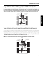
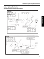
Torque Distribution with Lockout Disengaged (Inter-axle Differential is Operation)
Torque (power flow) from the vehicle driveline is transmitted to the input shaft and the inter-axle differential spider. At this point,
the differential distributes torque equally to both axles. For the forward axle, torque is transmitted from the helical-side gear to the
pinion helical gear, drive pinion, ring gear, wheel differential and axle shafts. For the rear axle, torque is transmitted from the output
shaft side gear, through the output shaft, inter-axle driveline, to the drive pinion, ring gear, wheel differential and axle shafts.
Input torque
Lockout disengaged
Drive is from differential
through helical gears to
forward gearing
Inter-axle differential
operating
Service Procedure
Drive is
from differential
through output
shaft to
rear gearing
Torque is transmitted to both axles through inter-axle differential action.
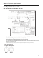
Torque Distribution with Lockout Engaged (inter-axle Differential is Not Operation)
A lockout mechanism is incorporated in the power divider to enable the vehicle driver to lock out the inter-axle differential and
provide maximum traction under adverse road conditions. In operation, an air cylinder (controlled by a cab-mounted valve) shifts
a sliding clutch. To lock out inter-axle differential action, the clutch engages the helical-side gear and causes this gear, the input
shaft and differential to rotate as one assembly. This action provides a positive drive to both axles. With Lockout engaged, torque
is distributed to both-axles without differential action. The forward axle pinion and ring gear are driven by the helical side gear.
The rear axle gearing is driven from the output shaft side gear and inter-axle driveline.
Note: Varied road surface conditions can result in unequal torque distribution between the two axle assemblies.
Input torque
Lockout engaged
Drive is from input shaft
through helical gears to
forward gearing
Inter-axle differential
not operating
Drive is from
output shaft side
gear to rear
gearing
Torque is transmitted to both axles without inter-axle differential action.
6
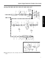
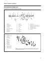
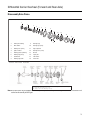
Spicer Single Reduction Tandem Drive Axles
Differential Carrier Assembly Exploded View
Forward Axle Carrier Assembly (Single Speed) with Diff. Lock
4
52 53
54
56
57
58
55
6
1
14
2 3
1
9
1
8
10
12
13
5
59
11
7
19
15
16
17 18
DIFFERENTIAL
& RING GEAR
20
30
LH
RH
21
22
23
24
33
29
31
32
35 34
38
36 37
34 35
28
27
26
25
Other Design Variations
Axle Series
D340, 380(P),400-P
D341, 381(P), 401-P, 402(P), 403(P), 451-P
Output Shaft Splines
16
16
Side Gear End
16
16
Output End
10
34
Input End
15
44
Diff End
36
36
Helical Gears
7 pitch
5 pitch
Forward Axle
10
41
Rear Axle
10
39
D340- 16
D341- 39
D380(P)- 16
D381(P), 402(P), 403(P)- 41
D400(P)- 33
D401-P, 451-P- 33
Input Shaft Splines
Drive Pinion Splines
Axle Shaft Side Gear Splines
7
Spicer Single Reduction Tandem Drive Axles
Axle Series D340, 380(P), 400-P, D341, 381(P), 401-P, 402(P), 403 (P), 451-P
61
60
62
63
64
65
INTER-AXLE
DIFFERENTIAL
ASSEMBLY
71
66
67 68
70
75 70
74 73
76
77
78
91 93
79 80 81
82
Service Procedure
69
72
92
83
84 85 86 88
89 90
87
106
105
39
31
40
41
42
43
45
46
44
43
47
40
48
50
49
51
LUBE PUMP
94
104 103 95
91
100
101
99
97 98
96
102
Note: Before Replacing Seals, Yokes, and Slingers, refer to the Repair and Replacement Instructions for interchangeability information.
8
Spicer Single Reduction Tandem Drive Axles
1 - Differential carrier & bearing caps
2 - Bearing capscrew
3 - Flat washer
4 - Lockwire
5 - Dowel bushing
6 - Bearing cap adjuster lock (RH)
7 - Capscrew
8 - Bearing cap adjuster lock (LH)
9 - Cotter pin (LH)
10 - Expansion plug (upper)
11 -Expansion plug (lower)
12 - Filler plug
13 - Shift fork shaft
14 - Carrier cover dowel pun
15 - Shift unit mounting stud
16 - Shift fork seal & spring assembly
17 - Flat washer
18 - Stud nut
19 - Shift fork & roller assembly
20 - Shift unit assembly
21 - Sliding clutch
22 - Differential bearing adjuster (RH)
23 - Differential bearing cup (RH)
24 - Differential bearing cone (RH)
25 - Differential bearing adjuster (LH)
26 - Differential bearing cup (LH)
27 - Differential bearing cone (LH)
28 - Differential case (plain half)
29 - Differential case (flanged half)
30 - Differential case capscrew
31 - Ring gear & drive pinion
32 - Bolt
33 - Nut
34 - Differential side gear
36 - Side pinion
37 - Side pinion thrust washer
38 - Spider
39 - Pinion pilot bearing
40 - Pinion bearing cone
41 - Pinion bearing spacer washer
42 - Pinion bearing spacer
43 - Pinion bearing cup
44 - Pinion bearing cage
45 - Pinion bearing cage shim
46 - Lock washer
47 - Bearing cage capscrew
48 - Pinion helical gear
49 - Outer pinion support bearing (one
piece)
50 - Pinion shaft end nut
51 - Pinion nut spring pin
52 - Output shaft nut
53 - Output shaft washer
54 - Rear bearing retaining washer
55 - Axle housing cover
56 - Output shaft oil seal
57 - Bearing snap ring
58 - Output shaft bearing
59 - Filler plug
60 - Output shaft
61 - Output shaft bushing
62 - Output shaft O-ring
63 - Output shaft bearing cup
64 - Output shaft bearing cone
65 - Output shaft side gear
66 - Side gear snap ring
67 - Output shaft compression spring
68 - Output shaft thrust bearing
69 - Inter-axle differential assemble
70 - Inter-axle differential case half
71 - Case bolt
72 - Case nut
73 - Side pinion
74 - Side pinion thrust washer
75 - Spider
76 - Helical side gear snap ring
77- Helical side gear
78 - Helical side gear bushing
79 - Helical side gear thrust washer
80 - Helical side gear “D” washer
81 - Lockout sliding clutch
82 - Input shaft
83 - Input shaft bearing cone
84 - Input shaft bearing cup
85 - Input cover shim
86 - Input bearing cover
87 - Bearing cover capscrew
88 - Input shaft oil seal
89 - Input shaft nut washer
90 - Input shaft nut
91 - PDU carrier cover
92 - Carrier cover capscrew
93 - Lock washer
94 - Pipe plug
95 - Expansion plug
96 - Magnetic filter screen
97 - Pump gear & shaft assembly
98 - Cover O-ring
99 - Lube pump cover
100 - Lock washer
101 - Cover capscrew
102 - Cover dowel pin
103 - Pump drive gear
104 - Drive gear locknut
105 - Air-operated lockout assembly
106 - Shift fork & push rod assembly
9
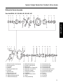
Spicer Single Reduction Tandem Drive Axles
Differential Carrier Assembly
Rear Axle RS340, 341, 380, 400, 401, 402, 403, 451
10
4
12
3
15
18
20
16
17
6
8
21
17
18
19
13
15
14
9
27
12
11
10
Service Procedure
2
11
14
26
28
25
26
23
30
33
5
6
5
1
1
1 - Differential carrier & bearing caps
2 - Bearing capscrew
3 - Flat washer
4 - Lockwire
5 - Bearing cap adjuster lock
6 - Cotter pin
7 - Dowel bushing
8 - Ring gear thrust screw
9 - Thrust screw jam nut
10 - Differential bearing adjuster
11 - Differential bearing cup
22
13
23
24
12 - Differential bearing cone
13 - Ring gear & drive pinion
14 - Bolt and nut
15 - Differential case (flanged half)
16 - Differential case capscrew
17 - Differential side gear
18 - Side gear thrust washer
19 - Side pinion
20 - Side pinion thrust washer
21 - Spider
22 - Pinion pilot bearing
29
31
32
23 - Pinion bearing cone
24 - Pinion bearing spacer
25 - Pinion bearing cage
26 - Pinion bearing cup
27 - Pinion bearing spacer washer
28 - Pinion bearing cage shim
29 - Bearing cage capscrew
30 - Oil seal
31 - Input yoke
32 - Flat washer
33 - Pinion nut
10
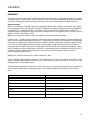
Lubrication
Lubrication
The ability of a drive axle to deliver quiet, trouble free operation over a period of years is largely dependent upon the use of good
quality gear lubricant in correct quantity. The most satisfactory results can be obtained by following the directions contained in
this manual. The following lubrication instructions represent the most current recommendations from Dana Corporation.
Approved Lubricants
General—Gear lubrications acceptable under military specification (MILSPEC) MIL-L-2105D (Lubricating Oils, Gear, Multipurpose) are approved for use in Spicer Drive Axles. The MIL-L-2105D specification defines performance and viscosity requirements
for multigrade oils. It supersedes both MIL-L-2105B, MIL-L-2105C and cold weather specification MlL-L-l 0324A. This
specification applies to both petroleum-based and synthetic based gear lubricants if they appear on the most current “Qualified
Products List” (QPL-2105) for MIL-L-2105D.
Note: The use of separate oil additives and/or friction modifiers are not approved in Dana Drive Axles.
Synthetic based — Synthetic-based gear lubricants exhibit superior thermal and oxidation stability, and generally degrade at a
lower rate when compared to petroleum-based lubricants. The performance characteristics of these lubricants include extended
change intervals, improved fuel economy, better extreme temperature operation, reduced wear and cleaner component appearance. The family of Spicer TM gear lubricants represents a premium quality synthetic lube which fully meets or exceeds the
requirements of MIL-L-2105D. These products, available in both 75W-90 and 80 W-140, have demonstrated superior performance in comparison to others qualified under the MILSPEC, as demonstrated by extensive laboratory and field testing. For a
complete list of Spicer ® approved synthetic lubricants contact your local Spicer representative. See back cover of this
manual for appropriate phone number.
Makeup Lube — Maximum amount of non-synthetic makeup lube is 100/o.
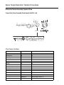
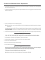
Viscosity / Ambient Temperature Recommendations -The following chart lists the varies SAE Grades covered by MIL-L- 2105D
and the associated ambient temperature range from each. Those SAE grades shown with an asterisk (*). are available in the
Roadranger family of synthetic gear lubricants.
The lowest ambient temperatures covered by this chart are -40°F and -40°C. Lubrication recommendations for those applications
which consistently operate below this temperature range, must be obtained through tcontacting your local Spicer epresentative.
Grade
Ambient Temperature
75W
- 40 F to -150 F (-40 C to -26 C)
75W-80
- 40 F to 80 F (-40 C to 21 C)
75W-90
- 40 F to 100 F (-40 C to 38 C)
75W-140
- 40 F and above (-40 C and above)
80W-90
- 40 F to 100 F (-40 C to -38 C)
80W-140
- 40 F and above(-40 C and above)
85W-140
- 40 F and above (-40 C and above)
11
Lubrication
Lube Change Intervals
This product combines the latest manufacturing and part washing technology. When filled with an Spicer approved synthetic
lubricant at the factory, the initial drain is not required.
Change the lubricant within the first 5,000 miles of operation when not using a Spicer approved synthetic lubricant in either a
new axle or after a carrier head replacement. Base subsequent lubricant changes on a combination of the following chart and
user assessment of the application and operating environment.
Guide Lines - Lube Change Intervals for Drive Axles
Lubricant Type
On-Highway Miles
Maximum change In- On/Off Highway Severe Maximum Change Interval
Service Miles
terval
Mineral Based
100,000
Yearly
40,000
Yearly
3 Years
100,000
Yearly
Roadranger Approved 250,000
Lubricant
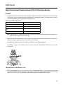
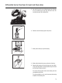
Changing Lube
Draining
Drain when the lube is at normal operating temperature. It will run freely and minimize the time necessary to fully drain the axle.
Unscrew the magnetic drain plug on the underside of the axle housing and allow the lube to drain into a suitable container. Inspect
drain plug for large quantities of metal particles. After initial oil change, these are signs of damage or extreme wear in the axle,
and inspection of the entire unit may be warranted. Clean the drain plug and replace it after the lube has drained completely.
Axles with Lube Pump: Remove the magnetic strainer from the power divider cover and inspect for wear material in the same
manner as the drain plug. Wash the magnetic strainer in solvent and blow dry with compressed air to remove oil and metal particles.
CAUTION
Exercise care to direct compressed air into safe area. Wear safety glasses.
12
Service Procedure
Severe Service Lubrication Change Intervals-Severe service applications are those where the vehicle consistently operates at or
near its maximum GCW or GVW ratings, dusty or wet environments, or consistent operation on grades greater than 8%. For these
applications, the ON/OFF HIGHWAY portion of the chart should be used. Typical applications are construction, logging, mining
and refuse removal.
Note: Remove metallic particles from the magnetic filler plug and drain plugs. Clean or replace the breather at each lubricant
change.
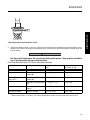
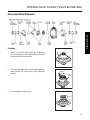
Lubrication
Filling
Remove the filler hole plug from the center of the axle housing cover and fill the axle with approved lubricant until level with the
bottom of the hole.
Forward axles: Add two pints (0.94 liters) of lubricant through filler hole at the top of the differential carrier near the power divider
cover.
Oil Filler Hole at top of Differential Carrier
Magnetic Strainer for Axle with Lube Pump
Note: Lube fill capacities in the adjacent chart are good guidelines but will vary somewhat on the basis of the angle the axle is
installed in a particular chassis. Always use the filler hole as the final reference. If lube is level with the bottom of the hole,
the axle is properly filled.
Axle Installation Angles
Axles installed at angles exceeding 10 degrees or operated regularly in areas of continuous and lengthy grades may require standpipes to allow proper fill levels.
For specific recommendations, contact your local Spicer representative. See back cover of this manual for phone numbers.
Lube Capacities, Dana Housings
Single Reduction Tandem Series
Forward Axle Pints (liters)
Rear Axle Pints (liters)
380(P), 381(P), 400-P, 401-P
39 (18.5)
36 (17.0)
402(P), 403(P),451-P
39 (18.5)
36 (17.0)
Forward Axle: Add an additional 2 pints (0.94 liters) axle lubricant through filler hole at the top of differential carrier near the power
divider cover.
Capacities listed are approximate. The amount of lubricant will vary with angle of axle as installed in vehicle chassis.
13
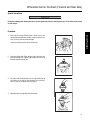
Lubrication
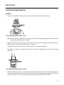
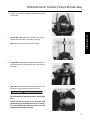
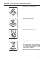
Wheel End Lubrication
IMPORTANT
Before operating the axle, the wheel hub cavities and bearings must be lubricated to prevent failure. When wheel ends are
serviced, follow Spicer’s wheel end lubrication procedure before operating the axle.
Spicer axles may be equipped with either of two wheel end designs:
•
Wheel ends with an oil fill hole.
•
Wheel ends without an oil fill hole.
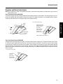
1.
Rotate the wheel end hub until the oil fill hole is up.
2.
Remove the oil fill plug.
3.
Pour 1/2 pint of axle sump lubricant into each hub through the wheel end fill hole.
4.
Install oil fill plug and tighten to specified torque.
Wheel End with Oil Fill Hole
Service Procedure
Wheel Ends with an oil fill hole proceed as follows: (Fig. 1)
Wheel End without Oil Fill Hole
WHEEL END
OIL FILL HOLE
LUBRICANT
FLOW
FROM SUMP
PROPER
LUBRICANT
LEVEL
PROPER
LUBRICANT
LEVEL
Fig. 1 Cutaway views of typical wheel and assemblies
14
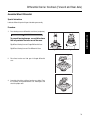
Lubrication
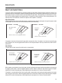
Wheel Ends without an oil fill hole proceed as follows: (Fig. 2)
1.
With axle level and wheel ends assembled, add lubricant through filler hole in axle housing cover until fluid is level with
the bottom of filler hole.
2.
Raise the left side of the axle 6 inches or more. Hold axle in this position for one minute.
3.
Lower the left side.
4.
Raise the right side of the axle 6 inches or more. Hold axle in this position for one minute.
5.
Lower the right side.
6.
With axle on a level surface, add lubricant through housing cover oil filler hole until fluid is level with the bottom of the
hole.
Note: Axles without wheel end fill holes will require approximately 2.5 additional pints of lubricant to bring the lube level even with
the bottom of fill hole.
WITH AXLE ON LEVEL
SURFACE FILL HOUSING
WITH OIL TO BOTTOM OF PLUG
TEMPERATURE SENSOR
MOUNTING HOLE
OIL WILL
RUN INTO
WHEEL END
OIL WILL
RUN INTO
WHEEL END
TILT HOUSING SIDE TO SIDE, 1 MINUTE PER SIDE, THEN,
RECHECK OIL LEVEL IN AXLE
Fig. 2 Wheel end lubrication procedure
15
General Information
Cleaning, Inspection, Replacement
As the drive axle is disassembled, set all parts aside for thorough cleaning and inspection. Careful inspection will help determine
whether parts should be reused. In many cases, the causes of premature wear or drive axle failure will also be revealed.
Cleaning
WARNING
Gasoline is not an acceptable solvent because of its extreme combustibiliy. It
is unsafe in the workshop environment.
Wash castings or other rough parts in solvent or clean in hot solution tanks using
mild alkali solutions. If a hot solution tank is used, make sure parts are heated thoroughly, before rinsing.
Rinse thoroughly to remove all traces of the cleaning solution. Dry parts immediately with clean rags.
Lightly oil parts if they are to be reused immediately. Otherwise, coat with oil and
wrap in corrosion-resistant paper. Store parts in a clean, dry place.
Inspection
Inspect steel parts for notches, visible steps or grooves created by wear. Look for
pitting or cracking along gear contact lines. Scuffing, deformation or discoloration
are signs of excessive heat in the axle, usually related to low lubricant levels or improper lubrication practices.
Before reusing a gear set, inspect teeth for signs of excessive wear. Check tooth
contact pattern for evidence of incorrect adjustment (see Adjustment Section for
correct pattern). Inspect machined surfaces of cast or malleable parts. They must
be free of cracks, scoring, and wear. Look for elongation of drilled holes, wear on
surfaces machined for bearing fits and nicks or burrs in mating surfaces.
Inspect fasteners for rounded heads, bends, cracks or damaged threads. The axle
housing should be examined for cracks or leaks. Also look for loose studs or
cross-threaded holes. Inspect machined surfaces for nicks and burrs.
16
Service Procedure
The differential carrier assembly may be steam-cleaned while mounted in the
housing as long as all openings are tightly plugged. Once removed from its housing, do not steam clean differential carrier or any components. Steam cleaning at
this time could allow water to be trapped in cored passages, leading to rust, lubricant contamination, and premature component wear. The only proper way to clean
the assembly is to disassemble it completely. Other methods will not be effective
except as preparatory steps in the process. Wash steel parts with ground or polished surfaces in solvent. There are many suitable commercial solvents available.
Kerosene and diesel fuel are acceptable.
General Information
Repair and Replacement
IMPORTANT
To achieve maximum value from an axle rebuild. Replace lower-cost parts, such as thrust washers, seals, etc. These items
protect the axle from premature wear or loss of lubricants. Replacing these parts will not increase rebuild cost significantly.
It is also important to replace other parts which display signs of heavy wear even though not cracked or broken. A significant
portion of such a parts useful life has been expended and the damage caused, should the part fail, is far in excess of its cost.
Steel Parts- Gear sets, input and output shafts, differential parts and bearings are not repairable. Worn or damaged parts should
be discarded without hesitation. Also discard mating parts in some cases. Gear sets, for example, must be replaced in sets.
Miscellaneous Parts - Seals and washers are routinely replaced. None of these parts can be reused if damaged. Fasteners using
self-locking nylon patches may be reused if not damaged, but should be secured by a few drops of Loctite #277 on the threaded
surface of the hole during installation and carefully torqued during installation.
Axle Housings - Repairs are limited to removal of nicks or burrs on machined surfaces and the replacement of loose or broken
studs.
CAUTION
Any damage which affects the alignment or structural integrity of the housing requires housing replacement. Repair by welding or straightening should not be attempted. This process can affect the housing heat treatment and cause it to fail completely when under load.
Silicone Rubber Gasket Compound - For more effective sealing. Spicer uses silicone rubber gasket compound to seal the
majority of metal-to-metal mating surfaces.
Spicer includes gasket compound and application instructions in many repair parts kits.
It is recommended that this compound be used in place of conventional gaskets. The compound will provide a more effective seal
against lube and is easier to remove from mating surfaces when replacing parts.
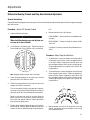
Seals, Yoke & Slinger Service Information
During the 4th Quarter of 1990, new seals and yoke & slingers were used on the models in this publication. The new seals and
slingers are noticeably different from the current seals and will affect interchangeability.
The upgraded seals can be used on axles originally equipped with the old seals.
Dana recommends the replacement of old yoke & slinger assemblies when the new seals are installed.
The old yokes and slingers will work with the new seals, but new yoke and slinger assemblies provide maximum sealing protection
and prevent premature seal wear due to poor yoke condition.
New yoke and slinger assemblies cannot be used with the old seal design on the tandem forward axles.
New yoke and slinger assemblies can be used with the old seal on the tandem rear pinions.
Yoke Assembly & Oil Seal Kits contain oil seal, yoke & slinger and instructions.
Most non-Dana aftermarket seals will not be compatible with the new Dana Yoke and Slinger assemblies.
Spcier recommends the use of special installation tools conveniently packaged in one single kit (listed below).
Refer to Dana parts Book AXIP-0089 and Eaton Bulletin 90-06 for additional information.
Seal Driver Installation Kit 272139
126917 Driver (Rear Axle Pinion)
127787 Adapter (use with 126917 Driver for Forward Axle Input)
127786 Driver (Forward Axle Output)
17
Adjustments
Wheel Bearing Adjustment
Special Instructions
WARNING
Never work under a vehicle supported by only a jack. Always support vehicle with stands. Block the wheels and make sure
the vehicle will not roll before releasing the brakes.
Procedure - Wheel End Seal
Remove:
•
The outer bearing and wheel.
•
The inner bearing.
•
The oil seal or grease retainer and discard.
•
The old wear sleeve (2-piece design only) with a ball peen hammer and discard.
Service Procedure
1.
IMPORTANT
Wheel end seals can be easily damaged during handling. Leave the seal in its package until installation to prevent damage or contamination.
CAUTION
Do not cut through the old wear sleeve. Damage to the housing may result.
2.
Inspect:
•
The spindle journal and hub bore for scratches or burns. Recondition with emery cloth as required.
Note: Deep gouges can be repaired by filling gouge with hardened gasket and smoothing with emery cloth.
3.
Clean:
•
The hub cavity and bearing bores before reassembly. Be sure to remove contaminants from all recesses and corners.
•
The bearings thoroughly with solvent and examine for damage. Replace damaged or worn bearings.
•
Before installation, lubricate with the same lubricant used in the axle sump.
•
The inner bearing.
•
The wheel seal following the directors provided by the seal supplier.
IMPORTANT
Always use the seal installation tool specified by the seal manufacturer. Using an improper tool can distort or damage
the seal and cause premature seal failure.
Procedure - Wheel Bearing Adjustment
1.
Identify the wheel nut system being installed. Three systems are available:
•
Three piece Dowel-type wheel nut system -Fig.1
•
Three piece Tang-type wheel nut system - Fig.2
18
Adjustments
•
Four piece Tang/Dowel type wheel nut system - Fig.3
WARNING
Do not mix spindle nuts and lock washers from different systems. Mixing spindle nuts and lock washers can cause wheel
separation.
Note: The lock washer for a four piece-dowel-type wheel system is thinner than the lock washer for a three piece tang-type
wheel nut system and is not designed to bear against the inner nut.
Fig 1
Fig 2
Outer nut
Outer nut
(P/N 119881)
(P/N 11249)
Inner nut
(P/N 119882)
Dowel Pin
Dowel-type Lock
Fig 3
Tang-type lock
washer (P/N 129132)
.0478" thick
Inner nut
Outer nut
(P/N 119881)
Tang-type lock washer
Dowel pin
(P/N 119883) 0.123" thick
Dowel-type lock
washer (P/N 119883)
Washer (P/N 119883)
2.
Inner nut
(P/N 119882)
(P/N 11249)
Inspect the spindle and nut threads for corrosion and clean thoroughly or replace as required.
Note: Proper assembly and adjustment is not possible if the spindle or nut threads are corroded.
•
3.
lnspect the tang-type washer (if used). Replace the washer if the tangs are broken, cracked, or damaged.
Install the hub and drum on the spindle with care to prevent damage or distortion to the wheel seal.
CAUTION
A wheel dolly is recommended during installation to make sure that the wheel seal is not damaged by the weight of the
hub and drum. Never support the hub on the spindle with just the inner bearing and seal. This can damage the seal and
cause premature failure.
•
4.
Completely fill the hub cavity between the inner and outer bearing races with the same lubricant used in the axle sump.
Before installation, lubricate the outer bearing with the same lubricant used in the axle sump.
Note: Lubricate only with clean axle lubricant of the same type used in the axle sump. Do not pack the bearing with grease
before installation. Grease will prevent the proper circulation of axle lubricant and may cause wheel seal failure.
5.
Install the outer bearing on the spindle.
•
Install the inner nut on the spindle.
•
Tighten the inner nut to 200 lbs. ft. (271 N.M.) while rotating the wheel hub.
CAUTION
Never use an impact wrench to adjust wheel bearings. A torque wrench is required to assure that the nuts are property
19
Adjustments
tightened.
6.
Back-off the inner nut one full turn. Rotate the wheel hub.
7.
Re-tighten the inner nut to 50 lbs. ft. (68 N.M.) while rotating the wheel hub.
8.
Back-off the inner nut exactly 1/4 turn.
Note: This adjustment procedure allows the wheel to rotate freely with 0.001"-0.005" (0.025mm to 0.1 27mm) end-play.
9.
Install the correct lock washer for the wheel nut system being used.
1.
Install the Tang-type lock washer on the spindle.
IMPORTANT
Never tighten the inner nut for alignment. This can preload the bearing and cause premature failure.
2.
Install the outer nut on the spindle and tighten to 250 lbs. ft. (339 N.M.).
3.
Verify end-play (see End Play Verification Procedure)
4.
After verifying end play, secure wheel nuts by bending one of the locking washer tangs over the outer wheel nut and another
tang over the inner wheel nut as shown in Figure 4. (below)
Bend two tangs…
one over inner nut
and one over
outer nut
Outer nut
Spindle
Inner nut
Lockwasher
Procedure - Three piece dowel-type lock washer system (see Fig. 1)
1.
Install the Dowel-type lock washer on the spindle.
Note: If the dowel pin and washer are not aligned, remove washer, turn it over and reinstall. If required, loosen the inner nut
just enough for alignment.
IMPORTANT
Never tighten the inner nut for alignment. This can preload the bearing and cause premature failure.
20
Service Procedure
Procedure - Three piece tang-type lock washer system (see Fig. 2).
Adjustments
2.
Install the outer nut on the spindle and tighten to 350 lbs. ft. (475 N.M.).
3.
Verify end-play (see End Play Verification Procedure)
Procedure - Four piece tang/dowel-type lock washer system (see Fig. 3)
1.
First, install the Dowel-type lock washer on the spindle.
Note: If the dowel pin and washer are not aligned, remove washer, turn it over and reinstall. If required loosen the inner nut
just enough for alignment.
IMPORTANT
Never tighten the inner nut for alignment. This can preload the bearing and cause premature failure.
2.
Install the Tang-type lock washer on the spindle.
3.
Install the outer nut on the spindle and tighten to 250 lbs. ft. (339 N. M.)
4.
Verify end-play (see End Play Verification Procedure)
5.
After verifying end play, secure the outer nut by bending two opposing (180° apart) tangs of the locking washer over the outer
nut as shown in Figure 5.
Figure 5
Bend two tangs
over outer nut
Spindle
Inner nut
Dowel pin
Outer nut
Lockwasher
Procedure - Install
1.
Install a new gasket at axle shaft flange.
2.
Install axle shaft.
3.
Install axle flange nuts and tighten to specified torque.
4.
Lubricate axle wheel ends (see Wheel End Lubrication Procedure)
Procedure - End Play Verification Procedure
1.
Verify that end-play meets specification using a dial indicator. An indicator with 0.001” (0.03 mm) resolution is required.
21
Adjustments
Wheel end play is the free movement of the tire and wheel assembly along the spindle axis.
2.
Attach a dial indicator with its magnetic base to the hub or brake drum as shown below:
With indicator mounted at bottom,
Push/Pull at sides of drum
Service Procedure
End Play Adjustment
with Tire & Wheel
Assembly
End Play Adjustment
with Wheel hub
3.
Adjust the dial indicator so that its plunger or pointer is against the end of the spindle with its line of action approximately
parallel to the axis of the spindle.
4.
Grasp the wheel assembly at the 3 o’clock and 9 o’clock positions. Push the wheel assembly in and out while oscillating it to
seat the bearings. Read bearing end play as the total indicator movement.
CAUTION
If end play is not within specification, readjustment is required.
Procedure - End Play Readjustment Procedure
1.
Excessive End Play - If end play is greater than.005” (.127 mm), remove the outer nut and pull the lock washer away from
the inner nut, but not off the spindle. Tighten the inner nut to the next alignment hole of the dowel-type washer (if used).
Reassemble the washer and torque the outer nut. Verify end play with a dial indicator.
2.
Insufficient End Play - If end play is not present, remove the outer nut and pull the lock washer away from the inner nut, but
not off the spindle. Loosen the inner nut to the next adjustment hole of the dowel-type washer (if used). Reassemble the washer and re-torque the outer nut. Verify end play with a dial indicator.
3.
Fine Tuning the End Play - If, after performing the readjustment procedures, end play is still not within the.001”-.005” (.025
mm to.127 mm) range, disassemble and inspect the components. If parts are found to be defective, replace the defective
parts, reassemble and repeat wheel bearing adjustment procedure. Verify end play with a dial indicator.
22
Adjustments
Differential Carrier Adjustments
Adjustments help provide optimum axle life and performance by correctly positioning bearings and gears under load. The tandem
axles covered in this manual require the following adjustments:
Bearing Preload: This adjustment is performed for both pinion and differential bearings. It maintains proper gear alignments by
creating correct bearing cone and cup relationships for free rotation under load. The pinion pilot bearing does not require a preload
adjustment.
Ring Gear Tooth Contact: This adjustment positions ring gear and pinion for best contact under load. Correct adjustment distributes torque evenly over gear teeth and helps maximize gear set Iife.
Input Shaft End Play (Forward Axles): This adjustment controls gear mesh in the inter-axle differential. Proper adjustment helps
maximize life of all power divider parts.
Adjust Input Shaft End Play
Specifications: Input shaft end play requirements will vary with operating conditions, mileage and rebuild procedures. These variations are shown in the following chart.
Input Shaft End Play
New or Rebuild with new parts: 0.003" to 0.007".
Rebuild with reused parts: 0.013" to 0.017".
Note: Because of manufacturing variations in individual parts, correctly adjusted end play could vary 0.010", after the unit is rotated.
Acceptable End Play Tolerances when measuring as a regular maintenance procedure with axle in truck.
Up to 0.060" with over 100,000 miles or 1 year service off-road.
Up to 0.040" with less than 100,000 miles or 1 year service on- road.
Note: If end play exceeds limits, disassemble power divider and replace worn parts.
Procedure - Measure and Adjust End Play
1.
IMPORTANT
In September 1988, a Spring and a Thrust Button between the input and output shafts. End play tolerances are the same
for axles with or without this Spring and Button. However, end play measurement procedure is different than described
below. Refer to Service Bulletin Supplement at back of this manual for procedure variances.
With power divider assembled to differential carrier, measure end play with dial indicator positioned at yoke end of input shaft.
Move input shaft axially and measure end play. If end play is not correct (see chart), adjust as follows.
2.
Remove input shaft nut, flat washer and yoke. Remove bearing cover cap screws and lock washers. Remove cover and shim
pack.
3.
To increase end play, add shims:
Desired end play: 0.003" to 0.007"
Measured endplay (Step 1): 0.001" - 0.001"
Add shims to provide desired end play : 0.002" to 0.006"
23
Adjustments
4.
To decrease end play, remove shims:
Measured end play (Step 1): 0.015" - 0.015"
Desired end play: 0.003" to 0.007"
Remove shims to provide desired end play : 0.012" to 0.008"
5.
To reassemble input shaft, install the adjusted shim pack and bearing cover. Install cap screws and lock washers. Torque
screws to 75-85 ft. lbs. (101-115 N.m).
Dial indicator
Service Procedure
U-bracket
Pry bar
Input shaft
Lift up on
pry bar to
compress
input shaft.
Measuring End Play with Dial Indicator
Note: If difficulty is experienced in achieving correct torque on the input yoke nut, torque the nut with truck on the ground
and axle shafts installed.
6.
Install yoke, flat washer and nut. Tighten nut snugly. Tap end of input shaft lightly to seat bearings.
7.
Measure input shaft end play with dial indicator. If end play is still incorrect, repeat Steps 2 through 6.
8.
With end play correct, seal shim pack to prevent lube leakage, then torque input shaft nut and cover cap screws (see chart).
Note: When power divider has been disassembled and reassembled, it may be desirable to adjust end play by measuring bearing cover clearance and calculating shim pack size. For procedures, see page 39.
Torque Chart
ft. lbs.
N.m
1 5/8 - 18
780-960
1057 - 1301
*M42 x 1.5
840 - 1020
1140 - 1383
Input Shaft Nut
Bearing Cover Capscrew
1/2 - 13
75 - 85
101 - 115
*Metric Nut used on Axles produced after 1-3-95
24
Adjustments
Pinion Bearing Preload
Special Instructions
Most late model axles are provided with a “press-fit” outer bearing on the drive pinion. Some of the early model axles use an outer
bearing which slips over the drive pinion. Procedures for adjusting both types of pinion bearing design are contained in this section.
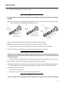
Procedure - Adjust Pinion Bearing Preload for Axles with “Press-fit” Outer Pinion Bearings
1.
Trial Build-up
Assemble pinion bearing cage, bearings and spacer (without drive pinion or oil seal). Center bearing spacer between two bearing cones.
Assemble these Parts for
Trial Build-up.
Bearing
Inter
Inter
Inner
bearing
bearing
cone
cone
spacer
Inner
bearing Bearing
(variable)
bearing
spacer
cup
cup
(variable)
Outer
Outer
bearing
bearing
cup
cup
Outer
Outer
bearing
bearing
cone
cone
Bearing
cage
Bearing
cage
Note: When new gear set or pinion bearings are used, select nominal size spacer from the specification chart below. If original parts are used, use spacer removed during disassembly.
2.
With the bearings well lubricated, place the assembly in the press. Position sleeve so that load is applied directly to the backface of the outer bearing cone.
Cage in Press
to Check Bearing
Preload.
Press
PressRam
ram
Sleeve Must
Sleeve
Applymust
Pressure
apply
to
To pressure
Back Face
back face of
Outer
outer Of
bearing
Bearing Cone
cone
SpringSpring
scale
Scale
25
Adjustments
3.
Apply press load (see chart below) to the assembly and check rolling torque. Wrap soft wire around the bearing cage, attach
spring scale and pull. Preload is correct when torque required to rotate the pinion bearing cage is from 10-20 in. lbs.. This
specification is translated into spring scale readings in the chart below.
Specifications for Pinion Bearing Trial Build-up Preload Test (“Press-fit” Outer Pinion Bearings)
Nominal Bearing
Thickness
Spacer
in.
mm
Tons
Metric Tons lbs.
Kgs.
380(P), 0.638
16.21
13.5 - 15.5
122- 140
3-7
2-3
D341, 381, (P), 0.496
401-P,
402(P),
403(P), 451-P
12.60
17 - 19
154 - 172
3-7
1.432
Rear Axles
16.21
14 - 15
127 - 136
4-8
1836
Axle Models
Press
Loads
Spring Scale Reading (without pinion
seal) (for 10-20 in. lbs. torque) (1.12.3 N.m)
Forward Axles
4.
0.638
If necessary, Adjust Pinion Bearing Preload by changing the pinion bearing spacer. A thicker spacer will decrease preload. A
thinner spacer will increase preload.
IMPORTANT
Once correct bearing preload has been established, note the spacer size used. Select a spacer
0.001” larger for use in the final pinion bearing cage assembly. The larger spacer compensates for
slight “growth” in the bearings which occurs when they are pressed on the pinion shank. The trial
build-up will result in proper pinion bearing preload in three of four cases.
Do not assume that all assemblies will retain proper preload once bearings are pressed on pinion
shank. Final preload test must be made in every case.
26
Service Procedure
D340,
400-P
Adjustments
Final Pinion Bearing Preload Test
Procedure 1.
Assemble the complete pinion bearing cage unit as recommending the assembly section of this manual.
Measuring Bearing Preload with Pinion in Vise
Note: Forward axle pinion is equipped with helical gear. For easier disassembly during bearing adjustment procedure, use a
dummy yoke (if available) in place of helical gear.
2.
Apply clamp load to the pinion bearing cage assembly. Either install the yoke (or helical gear) and torque the pinion nut to
specifications or use a press to simulate nut torque (see chart below).
Vise Method - If the yoke and nut are used, mount the assembly in a vise, clamping yoke firmly.
Press Method - If a press is used, position a sleeve or spacer so that load is applied directly to the back-face of the outer
bearing cone.
Measuring Bearing Preload with Pinion in Press
3.
Measure Pinion Bearing Preload - Use a spring scale to test the assembly rolling torque. To use the spring scale, wrap soft
wire around the bearing cage, attach the scale and pull. Preload is correct when torque required to rotate the pinion bearing
cage is from 15 to 35 in. lbs.. This specification is translated into spring scale readings in the chart below.
27
Adjustments
Final Pinion Bearing Preload Test
Axle Model
Nut Torque
ft. lbs. (N.m)
Press Load- Tons (Metric Spring Seal Reading (without
tons)
pinion seal)- lbs (kg)
Forward Axle
D340, 380(P), 400-P
560 - 700 (759 - 949) Self 13.5 - 15.5 (12.2 - 14.0)
Locking Nut
5-12 (2.3-5.4)
5-12 (2.3-5.4)
840-1020 (1140-1383) Metric 17 - 19 (15.4 - 17.2)
Nut
5-12 (2.3-5.4)
840* (1139) Slotted Nut and 17 - 19 (15.4 - 17.2)
role pin
5-12 (2.3-5.4)
560-700 (759-949)
6-14 (2.7-6.4)
Rear Axle (All models)
14-15 (12.7-13.6)
Service Procedure
D341, 381(P), 401-P, 402(P), 780 - 960 (1057-1301) Self 17 - 19 (15.4 - 17.2)
403(P), 451-P
Locking Nut
*Torque nut to 840 ft-lbs. (1 139 N.m), Then continue tightening nut to align nut slot to nearest hole in pinion shank.
4.
Adjust Pinion Bearing Preload - If necessary, adjust pinion bearing preload. Disassemble the pinion bearing cage as recommended in this -manual and change the pinion bearing spacer. A thicker spacer will decrease preload. A thinner spacer will
increase preload.
IMPORTANT
Use the correctly sized spacer. Do not use shim stock or grind spacers. These practices can lead to
loss of bearing preload and gear or bearing failure.
28
Adjustments
Adjust Pinion Bearing Preload for Axles with "Slip-fit" Outer Pinion Bearings
Procedure 1.
Lubricate bearings and assemble the drive pinion, bearings, and pinion bearing cage as recommended in the assembly section
of this manual. Use the pinion bearing spacer removed from the axle during disassembly. If the original spacer cannot be
used, install the nominal spacer recommended in the adjacent chart.
Nominal Pinion Bearing Spacers
Axle Model
Spacer Thickness in (mm)
Forward Axle
D340, 380(P), 400-P
0.638 (16.205)
D341, 381(P), 401-P, 402(P), 403(P), 0.492 (12.497)
451-P
Rear Axle (all models)
0.638 (16.205)
Note: Forward axle pinion is equipped with helical gear, For easier disassembly during bearing adjustment procedure, use a
dummy yoke (if available) in place of helical gear.
2.
Apply clamp load to the pinion bearings. Install the yoke (or helical gear) and torque the nut to specification or use a press to
simulate nut torque by applying pressure to the assembly (see chart below).
Vise Method - If the yoke and nut are used, mount the assembly in a vise, clamping yoke firmly.
Press Method - If a press is used, position a sleeve or spacer so that load is applied directly to the back-face of the outer
bearing cone.
Measuring Bearing Preload with Pinion in Vise
3.
Measure Pinion Bearing Preload - Use a spring scale to test the assembly rolling torque. To use the spring scale, wrap soft
wire around the bearing cage, attach the scale and pull. Preload is correct when torque required to rotate the pinion bearing
cage is from 15 to 35 in. lbs. This specification is translated into spring scale readings in the chart below.
29
Adjustments
4.
Adjust Pinion Bearing Preload - If necessary, adjust pinion bearing preload. Disassemble the pinion bearing cage as recommended in this manual and change the pinion bearing spacer. A thicker spacer will decrease preload. A thinner spacer will
increase preload.
IMPORTANT
Use the correctly sized spacer, Do not use shim stock or grind spacers. These practices can lead to
loss of bearing preload and gear or bearing failure.
Final Pinion Bearing Preload Test (Slip fit outer pinion bearings)
Axle Model
Nut Torque
ft. lbs (N.m)
Press Load- Tons (Metric Spring Seal Reading (without
tons)
pinion seal)- lbs (kg)
Forward Axle
D340, 380(P), 400-P
560 - 700 (759 - 949) Self 13.5 - 15.5 (12.2 - 14.0)
Locking Nut
5-12 (2.3-5.4)
D341, 381(P), 401-P, 402(P), 780 - 960 (1057-1301) Self 17 - 19 (15.4 - 17.2)
403(P), 451-P
Locking Nut
5-12 (2.3-5.4)
840-1020 (1140-1383) Metric 17 - 19 (15.4 - 17.2)
Nut
5-12 (2.3-5.4)
840* (1139) Slotted Nut and 17 - 19 (15.4 - 17.2)
role pin
5-12 (2.3-5.4)
560-700 (759-949)
6-14 (2.7-6.4)
Rear Axle (All models)
14-15 (12.7-13.6)
*Torque nut to 840 ft-lbs. (1 139 N.m), Then continue tightening nut to align nut slot to nearest hole in pinion shank.
30
Service Procedure
Measuring Bearing Preload with Pinion in Press
Adjustments
Differential Bearing Preload and Ring Gear Backlash Adjustment
Special Instructions
Correct differential bearing preload insures proper location of these bearings under load and helps position the ring gear for proper
gear tooth contact.
Procedure - Adjust Diff. Bearing Preload
1.
Lubricate differential bearings.
lash.
6.
IMPORTANT
USED GEARING — Reset to backlash recorded before disassembly.
When installing bearing caps and adjuster, exert care not to cross threads.
2.
Measure backlash with a dial indicator.
NEW GEARING — Backlash should be between 0.006”
and 0.016”.
Install adjusters and bearing caps. Tighten bearing cap
screws finger-tight. If this is difficult, use a hand wrench.
If backlash is incorrect, proceed as described below to readjust.
Procedure - Adjust Ring Gear Backlash
1.
To add backlash: Loosen the adjuster on the teeth side of
the ring gear several notches. Loosen the opposite adjuster one notch. Return to adjuster on teeth side of the ring
gear and tighten adjuster until it contacts the bearing cup.
Continue tightening the same adjuster 2 or 3 notches. Recheck backlash.
2.
To remove backlash: Loosen the adjuster on the teeth side
of the ring gear several notches. Tighten the opposite adjuster one notch. Return to adjuster on teeth side of ring
gear and tighten adjuster until it contacts the bearing cup.
Continue tightening the same adjuster 2 or 3 notches. Recheck backlash.
Note: Ring gear position for rear axle is illustrated.
3.
Loosen the bearing adjuster on the same side as the ring
gear teeth until its first thread is visible.
4.
Tighten the bearing adjuster on the back-face side of the
ring gear until there is no backlash.
One
One
notch
Notch
This can be tested by facing the ring gear teeth and pushing the gear away from the body while gently rocking the
gear from side to side. There should be no free movement.
Lugs
Lugs
Rotate the ring gear and check for any point where the
gear may bind. If such a point exists, loosen and re-tighten the back side adjuster. Make all further adjustments
from the point of tightest mesh.
5.
At teeth side of ring gear, tighten adjuster until it contacts
the bearing cup. Continue tightening adjuster two or three
notches and this will preload bearings and provide back-
3.
Moving adjuster one notch is the movement of the lead
edge of one adjuster lug to the lead edge of the next lug
past a preselected point.
31
Adjustments
Ring Gear and Pinion Tooth Contact
Note: Rear axle gearing is shown in the following instructions. Correct tooth contact patterns and adjustments are the same for
forward and rear axles.
Check Tooth Contact Pattern (NEW GEAR)
Paint twelve ring gear teeth with marking compound and roll the gear to obtain a contact pattern. The correct pattern is well-centered on the ring gear tooth with lengthwise contact clear of the toe. The length of the pattern in an unloaded condition is approximately one-half to two-thirds of the ring gear tooth in most models and ratios.
Correct Pattern New Gearing
Face
width
Heel
Top land
Root
Toe
Could vary in length.
Pattern should cover
1/2 tooth or more
(face width).
Service Procedure
Tooth
depth
Pattern should be
evenly centered
between tooth
top land and root.
Pattern should be clear of tooth toe.
Check Tooth Contact Pattern (USED GEAR)
Used gearing will not usually display the square, even contact pattern found in new gear sets. The gear will normally have a “pocket” at the toe-end of the gear tooth which tails into a contact line along the root of tooth. The more use a gear has had, the more
the line becomes the dominant characteristic of the pattern. Adjust used gear sets to display the same contact pattern observed
before disassembly. A correct pattern is clear of the toe and centers evenly along the face width between the top land and root.
Otherwise, the length and shape of the pattern are highly variable and is considered acceptable as long as it does not run off the
tooth at any point.
Correct Pattern Used Gearing
Pocket may be
extended.
Pattern along
the face width
could be longer.
32
Adjustments
Adjust Tooth Contact Patterns
If necessary, adjust the contact pattern by moving the ring gear and drive pinion. Ring gear position controls the backlash. This
adjustment moves the contact pattern along the face width of the gear tooth, Pinion position is determined by the size of the pinion
bearing cage shim pack. It controls contact on the tooth depth of the gear tooth. These adjustments are interrelated. As a result,
they must be considered together even though the pattern is altered by two distinct operations. When making adjustments, first
adjust the pinion, then the backlash. Continue this sequence until the pattern is satisfactory.
Adjust Pinion Position
If the gear pattern shows incorrect tooth depth contact, change drive pinion position by altering the shim pack. Used gears should
achieve proper contact with the same shims removed from the axle at disassembly.
INCORRECT
PATTERN
INCORRECT
Move pinion toward
ring gear.
PATTERN
Move pinion
away from
ring gear.
Pattern too close to tooth top land and off center.
Pattern too close or off tooth root.
If the pattern is too close to the top land of the gear tooth, remove pinion shims. If the pattern is too close to the root of the gear
tooth, add pinion shims. Check ring gear backlash after each shim change and adjust if necessary to maintain the 0.006” to 0.016”
specifications.
Adjust Backlash
If the gear pattern shows incorrect face width contact, change backlash.
INCORRECT
PATTERN
Move ring gear
away from pinion
to increase backlash.
Pattern too close to edge of tooth toe.
INCORRECT
PATTERN
Move ring gear
toward pinion
to decrease
backlash.
Pattern too far along tooth toward tooth heel.
With the pattern concentrated at the toe (too far down the tooth), add backlash by loosening the bearing adjuster on the teeth side
of ring gear several notches. Loosen the opposite adjuster one notch. Return to adjuster on teeth side of ring gear and tighten
adjuster until it contacts the bearing cup. Continue tightening the same adjuster 2 or 3 notches. Recheck backlash.
If the pattern is concentrated at the heel (too far up-the tooth), remove backlash by loosening the bearing adjuster on the teeth
side of ring gear several notches. Tighten the opposite adjuster one notch. Return to adjuster on teeth side of ring gear and tighten
adjuster until it contacts the bearing cup. Continue tightening the same adjuster 2 or 3 notches. Recheck backlash.
33
Fastener Tightening Specifications
Fastener Tightening Specifications
Specifications are for all axle models unless specified otherwise.
Service Procedure
34
Fastener Tightening Specifications
Dana Single Reduction Tandem Models
D340, 380(P), 400-P D341, 381 (P), 401-P, 402(P), 403(P), 451-P
Note 1: Metric Nut Used on Axles Produced After
1/3/95, Ref. Chart PG 56
•
Correct tightening torque values are extremely important to assure long Dana Axle life and dependable performance. Under-tightening of attaching parts is just as harmful as over-tightening.
•
Exact compliance with recommended torque values will assure the best results.
•
The data includes fastener size, grade and torque tightening values. Axle models are included to pinpoint identification
of fasteners for your particular axle.
•
To determine bolt or cap screw grade, check for designation stamped on bolt head (see illustration).
Bolt head markings
for grade identification
Grade 5
Grade 8
35
Forward Axle Differential Carrier Replacement
Remove Differential Carrier Assembly from Axle Housing
Special Instructions
IMPORTANT
D341, 381 (P), 401-P, 402(P), 403(P), 451-P models do NOT use and output shaft Rear Bearing Retaining Washer.
WARNING
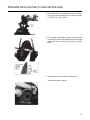
Procedure 1.
Drain axle lubricant
2
4
3
1
6
5
7
2.
Disconnect inner axle driveline.
3.
Remove output shaft but, flat washer and yoke.
4.
Disconnect differential lockout air line.
5.
Disconnect main driveline. Losen inputshaft yoke nut but do not remove.
6.
Remove stud nuts and axle shafts(if used, remove lockwashers and taper dowels.) If necessary, loosen dowels by holding a
36
Service Procedure
The output shaft rear bearing retaining washer is frequently lost when the differential carrier assembly is removed. It may
adhere to the yoke, to the face of the output shaft bearing, fall on the floor or into the housing. Locate this washer before
continuing! If it is not reinstalled, the end of the yoke will wear the output shaft bearing very quickly. If it is left in the housing,
it can be picked up by the ring gear motion and cause premature axle failure.
Forward Axle Differential Carrier Replacement
brass drift in the center of the shaft head and striking the drift with a sharp blow from a hammer.
IMPORTANT
Do not strike the shaft head with a hammer. Do not use chisels or wedges to loosen shaft or dowels.
7.
Remove nuts and lockwashers fastening the carrier to the axle housing. Remove the differentail carrier assembly.
WARNING
Do not lie under the carrier after fasteners are removed. Use transmission jack to support the differential carrier assemble during removal.
8.
Axle Housing Cover and Output Shaft Bearing Parts: The bearing parts can be replaced with cover removed or installed. If
necessary, remove axle housing cover. It is fastened with cap screws, nuts and lock washers.
9.
Remove oil seal and discard.
10. Remove bearing retaining washer.
IMPORTANT
D341, 381(P), 401-P, 402(P), 403(P), 451-P models do not use and output shaft rear bearing retaining washer.
11. If replacement is necessary, remove snap ring, rear bearing and bearing sleeve.
WARNING
Snap ring is spring steel and may pop off. Wear safety glasses when removing.
37
Forward Axle Differential Carrier Replacement
Install Differential Carrier Assembly
Special Instructions
IMPORTANT
D341, 381 (P), 401-P, 402(P), 403(P), 451-P models do NOT use and output shaft Rear Bearing Retaining Washer.
Before installing carrier assembly, inspect and thoroughly clean interior of axle housing.
WARNING
Note: Use silicone rubber gasket compound on axle housing mating surface as shown in the illustrations. Compound will set in
20 minutes. Install carrier and axle housing cover before compound sets or reapply.
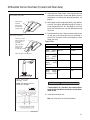
Procedure 1.
Apply silicone gasket compound. Install differential carrier assembly in axle housing. Install nuts and lock washers. Tighten
to correct torque. (See Chart).
SILICONE GASKET COMPOUND
PATTERN DIFFERENTIAL CARRIER
MATING SURFACE
SILICONE GASKET COMPOUND
PATTERN. HOUSING COVER
MATING SURFACE.
Location of hole in
rear cover.
Torque Chart
Size
Torque- ft. lbs. (N.m)
Differential Carrier
5/8-18 (Grade 8 stud)
220-240 (298-325)
Axle Housing Cover
7/16 - 20 (Grade 8 stod)
78-86 (94 - 116)
Cap screw size
7/16 - 14 (Grade 5)
48-56 (65 - 75)
5/8 - 18 (Grade 8)
220 - 240 (298 - 325)
2.
Axle Housing Cover and Output Shaft Bearing Parts. If removed, install cover and fasten with nuts, cap screws and lockwashers. Tighten to correct torque. If removed, install bearing parts (see steps 3 through 6).
38
Service Procedure
When installing differential carrier assembly, it is important to follow correct procedures to assure useful life. Failure to correctly install rear bearing and retaining washer could result in premature axle failure.
Forward Axle Differential Carrier Replacement
3.
Install output shaft rear bearing. Tap the outer race (with a sleeve or drift) until it is seated firmly in the machined pocket of
the cover. Secure with snap ring.
4.
Lubricate and install the rear bearing sleeve on the output shaft. Make certain it fits snugly against the shoulder at the forward
edge of the shaft splines.
5.
Install a new output shaft seal in the axle housing cover.*
Note: Check carrier date – code. on units built prior to 1988, Julian calendar date code could be found on the metal tag on
the differential.
Units built before March 13,1987 (87072), seal should be flush with bottom of chamfer. Units built after March 13,1987
(87072), seal should be installed until 3/32” deeper than bottom of chamfer. Lubricate the seal diameter to prevent damage
during yoke installation.
6.
Slide the rear bearing retaining washer over the splines of the outer shaft until it seats flush against the output shaft bearing.
IMPORTANT
*D341, 381(P), 401-P, 402(P), 403(P), 451-P models do NOT use an output shaft Rear Bearing Retaining Washer.
7.
Install output yoke, flat washer and self-locking nut. Tighten to correct torque.
8.
Install axle shafts, and stud nuts. (if used, also install lock- washers and taper dowels).
9.
Connect main and inter-axle drivelines.
10. Fill axle with correct lubricant (see Lubrication Section).
11. Connect differential lockout air line.
IMPORTANT
When axle has been disassembled or housing, gears, axle shafts or wheel equipment replaced, check axle assembly for
proper differential action before operating vehicle. Wheels must rotate freely and independently.
*Refer to page 13 for service information on seals, yokes & slingers.
Note: Washer not used on axles with metric threaded nuts. Reference bulletin AXIB-9409.
39
Power Divider Replacement
Power Divider Replacement (with differential carrier assembled to axle housing)
Special Instructions
The power divider can be replaced with the axle assembly in or out of chassis and with differential carrier assembled to axle housing.
WARNING
During removal and installation, the power divider assembly must be supported as a safety precaution. During removal or
installation, the lnter-axle differential may fall from carrier. Exert caution to prevent damage or injury.
Service Procedure
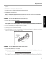
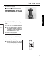
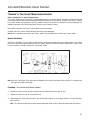
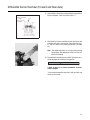
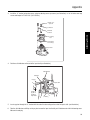
Procedure - Removing and Installing Power Divider
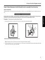
1.
With axle out of chassis, use chain hoist. Fasten chain to input yoke to remove power divider.
Removing Power Divider with Chain Hoist and Sling
Note: Lifting mechanism may create nicks and burrs on input yoke. Remove if present,
2.
With axle installed in chassis, use a transmission jack or a chain hoist and a sling. Wrap sling strap around power divider and
attach to chain hoist hook as shown in drawings.
40
Power Divider Replacement
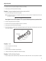
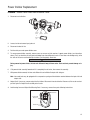
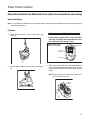
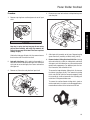
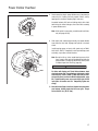
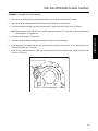
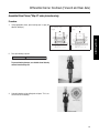
Procedure - Remove Power Divider from Differential Carrier
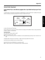
1.
Disconnect main driveline.
3.
2.
Lockout
Input
air line yoke nut
1.
Main
driveline
4.
Drain
pan
2.
Loosen, but do not remove input yoke nut.
3.
Disconnect lockout air line.
4.
Position drain pan under power divider cover.
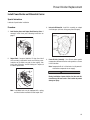
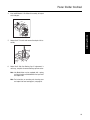
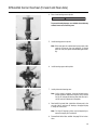
5.
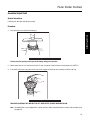
To remove power divider assembly, remove cover cap screws and lock washers. Support power divider (see instructions
above). Then, tap back-face of input yoke to dislodge cover from differential carrier. If cover does not dislodge easily, strike
the sides of the cover near the dowel pin locations (see illustration). Drain lube.
CAUTION
During removal of power divider, the lnter-axle differential may fall from carrier. Exert caution to prevent damage or injury.
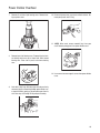
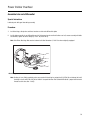
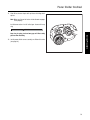
6.
Pull power divider assembly forward until it is completely free of carrier, then remove the assembly.
7.
With power divider removed, the inter-axle differential can be lifted off output shaft side gear .
Note: Late model axles may be equipped with a compression spring and thrust button mounted between the input shaft and
output shaft .
8.
Output Shaft. If necessary, remove output shaft as follows: Disconnect inter-axle driveline. Remove nut, flat washer and output shaft yoke. Pull output shaft assembly out of carrier.
9.
Axle Housing Cover and Output Shaft Bearing Parts. If necessary, remove these parts following instructions.
Dowel Pin
Socket Head
Capscrew
Dowel Pin
41
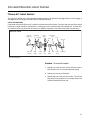
Power Divider Replacement
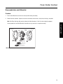
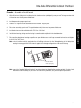
Install Power Divider on Differential Carrier
Special Instructions
Lubricate all parts before installation.
Procedure 1.
Axle Housing Cover and Output Shaft Bearing Parts. If
removed, install these parts following instructions on
page 27.
Output Shaft. If removed, lubricate "O" rings, then install
shaft assembly in differential carrier and housing cover.
Lubricate seal lip. Make sure yoke is clean and dry, then
install yoke, flat washer* and self-locking nut. Torque nut
to correct specification.
Inter-axle Differential- Install this assembly on output
shaft side gear (with nuts facing away from side gear).
Silicone Gasket Compound
Service Procedure
2.
3.
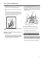
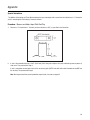
4.
Power Divider Assembly- Use silicone rubber gasket
compound on differential carrier mating surface as shown
in the illustration.
Note: Compound will set in 20 minutes. Install power divider before compound sets or reapply.
CAUTION
During installation of power divider, the inter-axle differential may fall from carrier. Exert caution to prevent
damage or injury.
Note: Late Model Axles may be equipped with a spring
and thrust button mounted in end of output shaft.
42
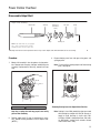
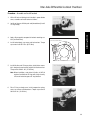
Power Divider Replacement
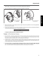
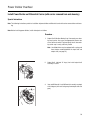
5.
Make certain dowel pins are installed in carrier (see drawing above), then install power divider assembly.
2.
Use a transmission jack or a chain hoist and sling (see
photo).
During installation, rotate input shaft to engage input shaft
splines with inter-axle differential, After installation, again
rotate input shaft to check for correct assembly. Output
shaft should turn when input shaft is rotated.
Check and Adjust Input Shaft End Play- With power divider assembled to differential carrier. Check end play with
dial indicator. If necessary, adjust end play. After input
shaft end play is within specifications, complete assembly
procedure as follows:
Dial indicator
U-bracket
Pry bar
Input shaf
Lift up on
pry bar to
compress
input shaft.
Measuring Input shaft End Play with Dial Indicator
Installing Power Divider Assembly with Chain Hoist and
Sling
Procedure - Installing Power Divider Assembly with
Chain Hoist and Sling.
1.
Install power divider cover cap screws and lock washers.
On pump models only, install socket-head cap screw in
correct location (see drawing on preceding page). Torque
cap screw to 110-125 ft. lbs. (149-170 N.m).
3.
Measuring Input Shaft End Play with Dial Indicator.
4.
Connect drivelines. Connect lockout air line.
5.
Fill axle to proper lube level (see Lubrication Section).
IMPORTANT
When axle has been disassembled or housing, gears,
axle shafts or wheel equipment replaced, check axle assembly for proper differential action before operating
vehicle. Wheels must rotate freely and independently.
*Washer not used on axles with metric threaded nuts.
43
Rear Axle Differential Carrier Replacement
Remove Differential Carrier Assembly from Axle Housing
1.
Drain Lubricant
2.
Disconnect inter-axle driveline.
Note: Use silicone rubber gasket compound on axle housing mating surface as shown in the illustration.
Compound will set in 20 minutes. Install carrier before compound sets or reapply.
Note: For easier disassembly, the drive pinion nut can be
loosened after driveline is disconnected.
3.
Remove axle shaft, stud nuts, lock washers and taper
dowels (if used). If necessary, loosen dowels by holding a
brass drift in the center of the shaft head and striking it a
sharp blow with a hammer.
IMPORTANT
Axle Housing Silicone Gasket Compound Pattern
Do not strike the shaft head with a hammer. Do not use
chisels or wedges to loosen shaft or dowels.
4.
5.
Remove nuts and lock washers fastening carrier to axle
housing. Remove differential carrier assembly.
Install differential carrier assembly in axle housing. Install
stud nuts and lock washers. Tighten to correct torque (see
chart).
IMPORTANT
WARNING
When axle has been disassembled or housing, gears,
axle shafts or wheel equipment replaced, check axle assembly for proper differential action before operating
vehicle. Wheels must rotate freely and independently.
Do not lie under carrier after fasteners are removed.
Use transmission jack to support and remove differential carrier assembly.
IMPORTANT
Before installing carrier assembly, inspect and thoroughly clean interior of axle housing.
6.
Install axle shafts and stud nuts.(If used, also install lock
washers and taper dowels.)
7.
Connect inter-axle driveline.
8.
Fill axle with correct lube [size 5/8-18 Grade 8, 220-240 Ft.
lbs. (298-325 N-m)].
44
Service Procedure
Procedure - Install Differential Carrier Assembly
Power Divider Overhaul
Remove Power Divider from Differential Carrier (with carrier removed from axle housing)
Special Instructions
Note: It is assumed that the differential carrier and power divider assembly have been removed from axle housing prior to starting
the following procedures:
Procedure 1.
CAUTION
Mount differential carrier in repair stand. Loosen input
shaft nut.
During removal of power divider, the lnter-axle differential may fall off input shaft from differential carrier.
Exert caution to prevent damage or injury.
Power Divider Cover
Dowel Pin Location
Dowel Pin
Socket Head
Capscrew
Dowel Pin
2.
Remove power divider cover cap screws and lock washers.
3.
Attach chain hoist to input yoke and lift power divider off
carrier, If power divider does not separate easily, strike the
cover near the dowel pin locations with a mallet (see illustration).
Note: Lifting mechanism may create nicks or burrs on input yoke. Remove if present.
45
Power Divider Overhaul
Inter-axle Differential. Lift differential assembly off output
shaft side gear.
5.
Output Shaft. Tilt carrier and remove the output shaft assembly.
6.
Output Shaft Side Gear Bearing Cup. If replacement is
necessary, use puller to remove bearing cup from carrier.
Service Procedure
4.
Note: Late Model Axles may be equipped with a spring
and thrust button mounted between the input shaft
and output shaft.
Note: For instructions on removing axle housing cover
and output shaft rear bearing parts, see page 26.
46
Power Divider Overhaul
Disassemble Power Divider Cover
Power Divider Cover and Input Shaft (without Lube Pump)
9
6
4
8
2
3
11
10
7
5
13
12
14
1
15
17
21
16
19
18
20
1
Snap ring
Capscrew
17
Bearing cover
2
Helical side gear
10
Bearing cup
18
3
Thrust washer
11
Shim
Lockout unit (See lockout service
instructions for design variations
4
D washer
12
Oil seal
19
Power divider cover
Shift fork and push rod
Bushings
9
5
Lockout sliding clutch
13
Yoke
20
6
Input shaft
14
Flat washer
21
7
Bearing cone
15
Nut
8
Lockwasher
16
Capscrew
1
Lock nut
2
Power divider cover
3
Pipe plug
4
Woodruff key*
5
O-ring
6
Pump cover
7
Capscrew
8
Lockwasher
9
Dowel pin
10
Pump gears
11
Magnetic strainer
12
Expansion plug
13
Pump drive gear
2
1
3
4
5
13
6
12
7
11
10
9
8
*NOTE: The drive shaft on early pump models is equipped with a woodruff key. On late pump models,
the key is eliminated. The drive shaft end has two machined flats and the drive gear mounting hole is
shaped to accommodate these flats.
47
Power Divider Overhaul
Procedure 1.
4.
Remove cap screws lock-washers and input bearing cover
and shim pack.
5.
Slide input shaft assembly out of cover. Remove bearing
spacer from shaft (used only on D340, 380(P), 400-P).
6.
Remove Lockout, Sliding Clutch and Shift Fork.. Starting
with axles built early in 1991, the sliding clutch and helical
slide gear curvic teeth diameter was increased to provide
greater tooth engagements. For additional parts and service information, refer to Bulletin 91-01.
Remove snap ring from machined groove at rear of input
shaft.
Service Procedure
WARNING
Snap ring is spring steel and may pop off wear safety
glasses when removing. with snap ring removed, the
helical side gear may fall off shaft. Exert care to prevent
damage or injury,
Slide helical-side gear off input shaft, then remove bronze
thrust washer and "D" washer from shaft.
2.
Axles with Lube Pump- At this point in disassembly, it is
desirable to remove lube pump drive gear nut. Hold input
shaft yoke to secure drive gear, then loosen and remove
drive gear nut.
3.
Remove nut, flat washer and yoke from input shaft.
To remove the larger-diameter sliding clutch, first remove
the lockout (see pages 40-42). Then remove the sliding
clutch and shift fork (with the two parts engaged). Grasp
the assembly by hand and maneuver the assembly past
restrictions in the power divider cover.
To remove the smaller-diameter sliding clutch, (used on
earlier model axles), the clutch can be disengaged and removed without removal of the lockout and shift fork.
48
Power Divider Overhaul
7.
Remove oil seal from input bearing cover. Remove bearing cup from cover.
10. Remove oil pump cover cap screws and lock washers. Remove pump cover and "O" ring.
11. *NOTE: When used, remove woodruff key from gear
shaft. Remove pump gears from power divider cover.
8.
Remove input shaft bearing cone. Temporarily place lockout sliding clutch over rear of input shaft, teeth toward
bearing cone. Place shaft in press and remove bearing
cone.
12. Unscrew and remove magnetic screen from power divider
cover.
9.
Axles with Lube Pump: With drive gear locknut previously
removed (step 2) and working through power divider cover input shaft bore, gently pry oil pump drive gear from its
shaft. See steps 10 through 12 for pump disassembly.
49
Power Divider Overhaul
Disassemble Inter-axle Differential
Procedure 1.
Punch mark differential case halves for correct position during reassembly.
2.
Remove locknuts and bolts. Separate case halves and remove thrust washers, side pinions, bushings, and spider.
Note: Side Pinion Bushings. Not used on tandems built after November 1, 1991. Use when originally equipped.
Current production Inter-Axle Differential Assemblies are only serviced as a complete assembly.
Punch
mark
Spider
Service Procedure
Case half
Case half
Bushing
Side pinion
Thrust washer
Non-Current Production Inter-Axle Differential
50
Power Divider Overhaul
Disassemble Output Shaft
Output Shaft Assembly
Output shaft
Bearing cup
(mounted in
carrier)
*Bushing
O-rings
Side gear
Spring
.
Bearing cone
Button
NOTE: Late Model Axles may be equipped
with a spring and thrust button mounted
between the input shaft and output shaft.
*Bushing removed from current production axles in Sept. 1994. Output shafts with P/N 129016 do not use bushings.
Procedure 1.
3.
Mount shaft assembly in vise using brass vise jaw protectors. Remove outer snap ring, side gear and bearing cone
assembly. If replacement is necessary, remove inner snap
ring.
Remove bearing cone from side gear using press and
split-type puller.
Note: For instructions covering output shaft rear bearing
parts, see page 26.
O-rings
WARNING
Snap ring is spring steel and may pop off, wear safety
glasses when removing.
2.
Remove output shaft "O" rings, If replacement is necessary, remove bushing mounted in end of output shaft.
(NOTE 1) .
Removing Bearing Cone from Output Shaft Side Gear
Note: Starting in June 1993, production axles were made
with bushing less output shaft 128736. Do not attempt to install bushings in shafts with P/N's
128736 or 129194* stamped into them. Ref. bulletin AXIB-93-06 *(output shaft w/metric threads
used in axles after 1-3-95).
51
Power Divider Overhaul
Assemble Output Shaft
Special Instructions
Lubricate parts with gear lube during assembly.
Procedure 1.
Press bearing cone on output shaft side gear.
Service Procedure
IMPORTANT
Provide protection against possible gear teeth damage during press operation.
2.
Mount output shaft in vise. Lubricate and install "O" rings. If removed, install bushing in end of output shaft. (NOTE 1)
3.
If removed, install inner snap ring on shaft, then install side gear and bearing cone assembly, and outer snap ring.
O-rings
WARNING
SNAP RING IS SPRING STEEL AND MAY POP OFF. WEAR SAFETY GLASSES WHEN INSTALLING.
Note: Late Model Axles may be equipped with a spring and thrust button mounted between the input shaft and output shaft
(see page 54).
52
Power Divider Overhaul
Assemble Inter-axle Differential
Special Instructions
Lubricate parts with gear lube during assembly
Procedure 1.
Install bushings, side pinions and thrust washers on inter-axle differential spider.
2.
Install spider assembly in one differential case half, align punch marks and install other case half, secure assembly with bolts
and locknuts, tighten to correct torque (17-23 ft. lbs, 23-31 N.m).
Note: Side Pinion Bushings. Not used on tandems built after November 1, 1991. Use when originally equipped.
Assembling Non-Current Production Inter-Axle Differentials
Note: Starting in June 1993, production axles were made with bushing less output shaft 128736. Do not attempt to install
bushings in shafts with P/N's 128736 or 129194* stamped into them. Ref. bulletin AXIB-93-06* (output shaft w/metric
threads used in axles after 1-3-95).
53
Power Divider Overhaul
Assemble Power Divider Cover
Power Divider Cover and Input Shaft
(without Lube Pump)
9
6
4
8
2
3
11
10
7
5
13
12
14
1
Service Procedure
15
17
21
16
19
18
20
1
Snap ring
2
Helical side gear
3
Thrust washer
4
5
9
LOCKOUT FOR DESIGN VARIATIONS REFER
TO LOCKOUT SERVICE INSTRUCTIONS
Capscrew
17
Bearing cover
10
Bearing cup
18
11
Shim
Lockout unit (See lockout service
instructions for design variations
D washer
12
Oil seal
19
Power divider cover
Lockout sliding clutch
13
Yoke
20
Shift fork and push rod
21
Bushings
6
Input shaft
14
Flat washer
7
Bearing cone
15
Nut
8
Lockwasher
16
Capscrew
Power Divider Cover with Lube Pump.
1
Lock nut
2
Power divider cover
3
Pipe plug
4
Woodruff key*
5
O-ring
6
Pump cover
7
Capscrew
8
Lockwasher
9
Dowel pin
10
Pump gears
11
Magnetic strainer
12
Expansion plug
13
Pump drive gear
2
1
3
4
5
13
6
12
7
11
10
9
8
*NOTE: The drive shaft on early pump models is equipped with a woodruff key. On late pump models, the key is eliminated. The drive shaft end has two
machined flats and the drive gear mounting hole is shaped to accommodate these flats.
Note: Axles with Lube Pump. Assemble and install lube pump and magnetic screen. See steps 1 to 4.
54
Power Divider Overhaul
Procedure 1.
See note on exploded view. Install pump gears in power divider cover (position gear with long shaft in opening adjacent to input shaft).
2.
Install "O" ring in pump cover, making sure "O" ring is seated
firmly in cover. If removed, install dowel pins. Install pump
cover on power divider cover and secure with cap screws
and lock washers. Tighten to correct torque (85-105 in. lbs.,
10-12 N.m).
3.
Install Pump Drive Gear. Install drive gear on pump shaft
end.
Note: Some pump drive shafts use a woodruff key. When
key is used. place key in shaft slot. Position gear on
shaft engaging key. Then install gear with driver and
hammer.
Note: Install and tighten drive gear nut after input shaft is
assembled to power divider cover (see step 10).
4.
Install magnetic screen in power divider cover. Tighten to
correct torque (40-60 ft. lbs., 54-81 N.m).
55
Power Divider Overhaul
5.
Press bearing cone on input shaft.
IMPORTANT
To prevent bearing damage, be careful to use
sleeve that only contacts the inner race of bearing cone.
Service Procedure
6.
SEAL INSTALLATION IMPORTANT: Before installing seal,
refer to page 13 for service information on Seals, Yokes &
Slingers.
Press oil seal in cover using a seal driver or suitable sleeve.
hen correctly
stalled, seal
ould be flush
th bottom of
amfer
Note: Check carrier date code (see page 27, note before 5).
Units built before October 26, 1987 (87299), seal
should be flush with bottom of chamfer. Units built after October 26, 1987 (87299), seal should be installed
until 3/32" deeper than bottom of chamfer.
Press bearing cup in input bearing cover.
IMPORTANT
For correct cup installation, use appropriate sleeve. Take
care to make sure cup is not cocked and is firmly seated
all around.
7.
Install bronze bushings in helical-side gear.
Note: Helical Gears made after 1/3/95 have a "step" at the
end of Inner Bore. Bushings must reinstalled from the
Curvic Tooth side, inward towards this step. Press
flush against the shoulder of the step.
1/32"
56
Power Divider Overhaul
8.
Check expansion plug in power divider cover (see photo) to
make sure it is in place and firmly seated. If loose, seat by
tapping with a hammer. Replace plug if necessary.
Assemble lockout shift fork and sliding clutch with clutch
teeth facing the helical-side gear, then install this assembly
in power divider cover.
Note: At this point in reassembly, assemble and install lockout (see pages 40-42).
Expansion plug
9.
Slide input shaft and bearing assembly into power divider
cover from the front side. Engage shaft splines in lock-out
clutch.
Install bearing spacer on input shaft (used only on D340,
380, 380-P, 400-P). Temporarily install input bearing cover
assembly, cap screws and lock washers.
Note: Do not install any shims under bearing cover at this
time. Correct shim pack will be determined after the
power divider is installed on differential carrier (Refer
to "Adjust Input Shaft End Play" page 39).
IMPORTANT
For Axles with Spring and Thrust Button between input
shaft and output shaft: For preliminary adjustment of input
shaft end play, install a 0.045" (0.024 mm) shim pack under bearing cover (see Service Bulletin Supplement, page
54). Tighten bearing cover cap screws finger-tight. Install
input yoke, flat washer and nut. Temporarily tighten nut
snugly.
10. Axles with Lube Pump: Install and tighten lube pump drive
gear locknut, holding input shaft to secure gear. Torque
nut to 35-45 ft. lbs. (47-61 N.m).
57
Power Divider Overhaul
11. Slide "D" washer over input shaft up to base of sliding clutch
splines.
Note: Make sure flat part of washer inside diameter engages
shaft properly.
Install bronze washer. Install helical gear. Secure with snap
ring.
WARNING
Service Procedure
Snap ring is spring steel and may pop off. Wear safety
glasses when installing.
12. Install power divider cover assembly on differential carrier
(see page 38).
58
Power Divider Overhaul
Install Power Divider on Differential Carrier (with carrier removed from axle housing)
Special Instructions
Note: The following instructions pertain to installation of power divider on differential carrier with carrier removed from axle housing.
Note: Before installing power divider, install related parts as follows
Procedure 1.
Output Shaft Side Gear Bearing Cup. If removed, press bearing cup in carrier. Use a press and appropriate sleeve or use
a brass drift and a mallet. Tap bearing cup into its' bore making certain cup is evenly and firmly seated.
Note: Late Model Axles may be equipped with a spring and
thrust button mounted between the input shaft and
output shaft (see page 54).
2.
Output Shaft. Lubricate "O" rings, then install output shaft
assembly in carrier.
3.
Inter-axle Differential. Install differential assembly on output
shaft side gear (with nuts facing away from output shaft side
gear).
59
Power Divider Overhaul
4.
Silicone Gasket Compound
Service Procedure
5.
Apply silicone gasket compound on carrier mating surface
(see illustration).
Install Power Divider. Attach chain hoist to input yoke and
install power divider assembly During installation, rotate input shaft to engage input shaft splines with inter-axle differential. After installation, again rotate input shaft. Output
shaft should turn when input shaft is rotated if assembly is
correct.
Note: Lifting mechanism may create nicks and burrs on input yoke. Remove if present.
6.
If removed, install dowel pins in carrier. Install power divider Power
cover cap screws and lock-washers. (On pump models only, Dowel
place socket-head cap screw at location shown on drawing.
Torque cap screws to 110-125 ft. lbs. (149-170 N.m).
Divider Cover
Pin Location
Dowel Pin
Socket Head
Capscrew
Dowel Pin
7.
Adjust Input Shaft End Play. Adjust end play with the power
divider assembled to the differential carrier. (See page 39.)
60
Power Divider Overhaul
Measure and Adjust Input Shaft End Play
Special Instructions
Note: After power divider overhaul and installation in power divider, check and adjust input shaft end play.
Correct end play when new parts are used in overhaul is 0.003" to 0.007", with reused parts 0.013" to 0.017". Refer to page 15 for
other variations.
IMPORTANT
September 1988, A Spring and a Thrust Button were added between the input and output shafts. End play tolerances are the
same for axles with or without this Spring and Button. However, end play measurement procedure is different than described
below. Refer to Service Bulletin Supplement at back of this manual for procedure variances.
Procedure 1.
Remove input shaft nut, flat washer and yoke. Remove input
bearing cover cap screws and lock washers. Remove bearing cover (and shim pack if installed).
2.
Reinstall bearing cover without shims. Hold in position with
hand pressure and measure clearance between power divider cover and bearing cover, using a feeler gauge.
3.
The bearing cover clearance measured in Step 2 plus 0.005"
will equal shim pack thickness required for desired end play
(rebuild with new parts). Add 0.015" to shim pack for rebuild
with used parts.
Install shim pack and bearing cover. Install cap screws and
lock-washers, Torque screws to 75-85 ft. lbs. (101-115
N.m).
4.
Install yoke, flat washer and nut. Tighten nut snugly. Tap end
61
Power Divider Overhaul
of input shaft lightly to seat bearings.
Dial indicator
U-bracket
Pry bar
Input shaft
5.
If end play is incorrect, change shim pack size, as follows:
Service Procedure
6.
Check input shaft end play with dial indicator positioned at
yoke end of input shaft. Move input shaft axially and measure end play. If end play is correct, seal shim pack to prevent lube leakage then torque input shaft nut and cover cap
screws (see chart).
Lift up on
pry bar to
compress
input shaft.
Add shims to increase end play.
Example: Desired end play (New Parts): 0.003" to 0.007"
Measured end play (Step 6): 0.001" - 0.001"
Add shims to provide desired end play: 0.002" to 0.006"
Remove shims to decrease end play.
Example: Measured end play (Step 6): 0.015" - 0.015"
Desired end play (New Parts): 0.003" to 0.007"
Remove shims to provide desired end play: 0.012" to 0.008"
7.
To add or remove shims, remove input shaft nut, flat washer
and yoke. Remove cap screws, lockwashers and bearing
cover. Add or remove shims as required.
8.
Install bearing cover, cap screws and lockwashers. Install
yoke, flat washer and nut. Seal shim pack to prevent lube
leakage then torque input shaft nut and cover cap screws
(see chart).
Torque Chart
Size
Ft. lbs.
N.m
1-5/8 -18
780-960
1057-1301
M42 x 1.5
840-1020
1140-1383
Input Shaft Nut
Bearing Cover Cap Screw
1/2-13 (Grade 5)
75-85
101-115
*Metric Nut used in Production Axles after 1/3/95
62
Inter-Axle Differential Lockout Overhaul.
"Standard" or "Current" Model Lockout Overhaul
Special Instructions
Three differential model lockouts are used on Dana Tandem Axles. To identify the lockout used on your axle, refer to the illustrations and related service instructions below.
“Standard” Lockouts (Current and Non-Current Models). The “current” model is an improved version of and replaces the “noncurrent” lockout. Both are air-operated to engage the lockout and spring-released to disengage the lockout.
Dana Axles may be equipped with either of these lockouts. The “current” model is interchangeable with the “non-current” model
as an assembly. For service information, refer to the following page.
“Reverse-Air” Lockout. The “Reverse-Air” lockout is spring- operated to engage the lockout and air-operated to disengage the
lockout. This model is similar to the “non-current” “standard” lockout. It is not available in the new “current” lockout.
Procedure - Disassemble and Remove Lockout.
1.
With axle installed in vehicle, place differential lock selector valve in the disengaged (or unlocked) position. Disconnect the
air line at the lockout piston housing.
Cylindrical
design
“Standard” “Current” Model Lockout
2.
Remove cap screws and lock washers fastening mounting bracket to power divider cover. Remove bracket and piston housing.
3.
Remove locknut, piston with “O” ring, compression spring and shoulder washer from push rod.
Note: The shift fork and push rod cannot be removed with power divider cover installed (see Power Divider instructions).
63
Inter-Axle Differential Lockout Overhaul.
Procedure - Assemble and Install Lockout
With shift fork and sliding clutch installed, place the shoulder washer (white plastic) over push rod. The large diameter side
of the washer must face the power divider cover.
2.
Install compression spring on push rod.
3.
Lubricate “O” ring with silicone-based lubricant and install “O” ring on piston.
4.
Place piston assembly on push rod. The large diameter end of piston must face power divider cover.
5.
Install locknut on push rod and tighten to 13-17 lft. lbs. (l8-23 N.m).
6.
Install piston housing, making sure the housing is correctly seated and piloted in the shoulder washer.
7.
Place mounting bracket over housing and position on power divider cover. Install cap screws and lock washers and tighten
to 48-56 ft. lbs. (65-76 N.m).
Note: If axle is installed in vehicle, apply sealant to air line fitting and connect air line. When tightening air line, hold piston
housing in mounting position using a wrench applied to the hexagon configuration at outer end of housing.
Shoulder washer
must seat properly
Note: A new style “Inter-Axle Differential Lockout” was being released as this publication was being printed. If the Inter- Axle
Differential Lockout Assembly on your axle is not shown in this publication, call your local Spicer representative.
64
Service Procedure
1.
Inter-Axle Differential Lockout Overhaul.
"Standard" or "Non-Current" Model Lockout Overhaul
Retrofit “Non-Current” to “Current” Model Lockout
The “current” model (only as an assembly) is interchangeable with the “non-current” lockout. The original shift fork and push rod
can be used for either model lockout and need not be replaced. Retrofit Kits are available to convert the “non-current” model to
the “current” lockout. Parts (except the shift fork), included in these kits are shown in the illustration on the preceding page. For
additional information, refer to Dana Parts Books (see back cover). Retrofit as follows:
Disassemble and remove “non-current” lockout. Refer to instructions below.
Assemble and install “current” lockout following instructions on preceding page.
Note: Do not use mounting screws from “non-current” model. They are too long to use with the new “current” model.
Special Instructions
Service Parts Availability: The “non-current” lockout assembly, body, piston and body cover are no longer available. If any of these
items are not serviceable, replace lockout with the new “current” model per instructions above. For other parts, a Service Parts
Kit (see illustration) is available to service the “non-current” lockout.
“Standard” “Non-Current” Model Lockout
*Asterisk Identifies parts included in Service Kit 211201
Note: Axles with Lube Pumps: These axle models are equipped with a piston stop located at base of piston. It is important that
this stop be reinstalled in reassembly.
Procedure - Disassemble and Remove Lockout
1.
Remove cap screws and lock washers fastening cover to the body. Remove cover and “O’’ ring.
2.
Remove nut, flat washer and “O’’ ring from push rod.
3.
Remove body cap screws and lock washers, then remove body and piston as an assembly. Remove “O’’ ring and felt oilers
from the piston.
Note: The shift fork and push rod cannot be removed with power divider cover installed (see Power Divider instructions).
65
Inter-Axle Differential Lockout Overhaul.
Procedure - Assemble and Install Lockout
1.
With shift fork and sliding clutch installed in power divider cover, assemble and install lockout as follows.
2.
Apply silicone gasket compound to mounting surface on power divider cover. See illustration.
3.
Install lockout body. Secure with cap screws and lock washers. Torque cap screws to 48-56 ft. lbs. (65-76 N.m).
Note: Before installation, soak piston felt oilers in SAE 30 engine oil and lubricate “O’’ rings with a high-viscosity silicone oil
or barium grease “O’’ ring lubricant.
Install felt oilers and large “O” ring on piston.
5.
Axles with Lube Pump. Before installing piston, place piston stop at base of lockout body.
6.
Install compression spring over shift fork push rod. Install piston in body and secure with “O” ring, flat washer and nut.
Torque nut to 20-26 ft. lbs. (27-35 N.m).
7.
Install “O’’ ring in lockout body cover. Install cover and secure with cap screws and lock washers. Torque cap screws to 96108 in. lbs. (10-12 N.m).
Lockout Silicone Gasket Pattern
66
Service Procedure
4.
Inter-Axle Differential Lockout Overhaul.
"Reverse-Air" Lockout Overhaul
The "reverse-air" lockout unit is spring-operated to engage lockout and air-operated to disengage lockout. A clutch engages or
disengages the helical-side gear to lock or unlock the inter-axle differential.
Service Parts Availability
A new design of the original "Reverse-Air" Lockout has not been released at this writing. The piston, body and cover of the original
lockout are no longer available as individual parts. If these parts are not serviceable, replace the complete unit. For other parts,
use a Service Parts Kit (see illustration for contents). For additional information, refer to Dana Parts Books (see back cover).
"Reverse-Air" Lockout
Shift fork
and push rod
Lockwasher
Capscrew
Piston
O-ring
Compression
spring
Cover*
Piston*
Push rod
seal ring
Body
O-ring
Lockout
body*
Felt
oilers
Flat
washer
Capscrew
Nut
Cover
O-ring
Lockwasher
*Non-serviceable parts
Procedure - Disassemble Lockout.
1.
Remove cap screws and lock washers fastening cover to
body. Remove cover, "O" ring and compression spring.
2.
Remove push rod nut and flat washer.
3.
Remove body cap screws and lock washers. Then remove
body, body "O" ring, and piston as an assembly. Remove seal
ring from threaded end of push rod.
67
Inter-Axle Differential Lockout Overhaul.
Procedure - Assemble and Install Lockout
With shift fork and sliding clutch installed in power divider
cover, assemble and install lockout as follows:
2.
Install seal ring on shift fork push rod (threaded end). Install
"O" ring in body.
3.
Apply silicone gasket compound to lockout mounting surface (see illustration).
4.
Install lockout body, cap screws and lock washers. Torque
cap screws to 48-56 ft. lbs. (65-76 N.m).
5.
Install felt oilers and "O" ring on piston. Install piston assembly in body and secure to push rod with flat washer and nut.
Torque nut to 20-26 ft. lbs. (27-35 N.m).
Service Procedure
1.
Lockout Silicone Gasket Pattern
Note: Before installation, soak piston felt oilers in SAE 30
engine oil and lubricate "O" rings with a high-viscosity
silicone oil or barium grease "O" ring lubricant.
6.
Place "O" ring on body cover. Install compression spring,
cover, cap screws and lockwashers. Torque cap screws to
96-108 in. lbs. (10-12 N.m).
68
Differential Carrier Overhaul (Forward and Rear Axle)
Disassemble Differential Carrier (with power divider removed)
Special Instructions
If gear set is to be reused, check tooth contact pattern and ring gear backlash before disassembling differential carrier. Best results
are obtained when established wear patterns are maintained in using gearing. Omit this step if the gear set is to be replaced.
Procedure 1.
Mount differential carrier in repair stand.
Note: For easier disassembly, loosen but do not remove
pinion self-locking nut. When forward axle pinion is
equipped with slotted nut, remove roll pin with a pin
punch then loosen nut.
2.
Punch mark differential bearing caps. If reusing gear set,
also punch mark bearing adjusters for reference during assembly.
3.
Cut lock-wire. Remove cap screws, flat washers and bearing
caps.
69
Differential Carrier Overhaul (Forward and Rear Axle)
Using a chain hoist, lift ring gear and differential assembly
out of carrier.
5.
Forward Axle: Remove pinion nut (see NOTE under Step 1).
Remove helical drive gear, using puller if necessary.
Service Procedure
4.
Note: Remove outer pinion bearing cone if Slip-fit.
6.
Forward Axle: Remove pinion bearing cage cap screws. Remove drive pinion and cage assembly from carrier. Remove
shim pack.
7.
Rear Axle: Remove pinion bearing cage cap screws, then
drive pinion, cage and yoke assembly out of carrier.
IMPORTANT
Do not allow pinion to drop on hard surface. Remove shim
pack.
Forward and Rear Axle: If gear set is to be reused, keep
pinion bearing cage shim pack intact for use in reassembly. If the original shims cannot be reused, record the
number and size of shims in the pack.
70
Differential Carrier Overhaul (Forward and Rear Axle)
Disassembly Drive Pinion
Rear Axle Pinion Illustrated.
1
2
3
4
5
6
8
9
10
12
13
14
15
16
7
1
Pinion pilot bearing
2
Drive Pinion
10
Bearing cup (outer)
3
Bearing cone (inner)
11
Cage capscrew
4
Spacer washer
12
Bearing cone (outer)
5
Bearing spacer (variable)
13
Oil seal
6
Bearing cup (inner)
14
Input yoke
7
Lockwasher
15
Flat washer
8
Bearing cage shim
16
Pinion nut
9
11
Bearing cage
Forward Axle Pinion Illustrated.
ïD341, 381(P), 401-P, 402(P), 403(P), 451-P use self-locking or slotted nut and roll pm.
Metric self-locking nuts used as of 1-3-95.
D340, 380(P), 400-P use self-locking nut only.
Note: Dana drive axles may be equipped with either slip-fit or press-fit outer pinion bearings. Procedures are contained in-this
section for disassembly of both types.
71
Differential Carrier Overhaul (Forward and Rear Axle)
Special Instructions
IMPORTANT
During the following yoke removal procedure, the drive pinion may fall out of bearings and cage. Do not allow pinion to drop
on hard surface.
Procedure Rear Axle Pinion Yoke: Remove yoke. If pinion nut was not
loosened during earlier disassembly, clamp assembly in vise
jaws, use brass pads to prevent damage.
Service Procedure
1.
Loosen and remove pinion nut and flat washer.
2.
Forward and Rear Axle Pinion Bearing Cage: For pinion with
press-fit bearing cone, support cage and press pinion out of
bearing cage and bearing cone.
3.
For pinion with slip-fit bearing cone, the cage, outer bearing
and pinion can usually be disassembled easily without a
press. If difficulty is experienced, use a press.
4.
Removing Bearing Cage (Rear Axle illustrated).
72
Differential Carrier Overhaul (Forward and Rear Axle)
5.
Rear Axle Pinion Oil Seal and Outer Bearing Cone: Remove
oil seal and bearing cone from cage. Discard oil seal. Remove bearing cups with suitable puller.
6.
Remove and retain bearing spacer from pinion.
7.
Mount puller vertically to split the bearing.
8.
Mount puller horizontally to press pinion out of bearing.
9.
Remove pilot bearing and inner bearing cone from pinion,
using a split-type puller. Use two procedure steps to remove
each bearing (see photos above).
This action will force puller halves under bearing and start
moving bearing off pinion.
The same procedure can be used to remove pilot bearing
and pinion inner bearing cone.
73
Differential Carrier Overhaul (Forward and Rear Axle)
Disassemble Wheel Differential
Service Procedure
Procedure 1.
Remove nuts and bolts fastening ring gear to differential
cases, allowing gear to fall free. If gear does not fall, tap outer diameter with soft mallet to loosen.
2.
Punch mark differential cases for correct location during assembly. Remove cap screws and lift off plain differential
case half.
3.
Punch
Punch
marks
Marks
Lift out side gear and thrust washer.
74
Differential Carrier Overhaul (Forward and Rear Axle)
4.
Lift out spider, side pinions and thrust washers.
5.
Remove side gear and thrust washer.
6.
Puller Mounted Vertically to Split Bearing.
7.
Remove bearing cones from case halves using suitable puller (see photos).
8.
Removing Bearing Cone from Flanged Case Half.
Remove bearing cone from plain case half in two steps:
First, mount puller vertically to split bearing (see photo).
This action will start moving bearing off case. Second,
mount puller vertically to remove cone.
9.
Remove bearing cone from flanged case half using suitable
puller.
75
Differential Carrier Overhaul (Forward and Rear Axle)
Assemble Wheel Differential
Special Instructions
Lubricate differential parts with gear lube during reassembly
Procedure 1.
Press bearing cones on differential case halves (see photos).
IMPORTANT
Service Procedure
To prevent bearing damage, use suitable sleeve
that only contacts the inner race of the cone.
Fig A: Press Bearing Cone on Flanged Differential Case.
Fig B: Press Bearing Cone on Plain Differential/ Case.
Fig A
2.
Place thrust washer and side gear in flanged differential
case.
3.
Assemble side pinion and thrust washers on spider. Place
this assembly in flanged differential case. Rotate gears and
check for proper mesh.
Fig B
76
Differential Carrier Overhaul (Forward and Rear Axle)
4.
Place side gear and thrust washer on side pinions.
5.
Align punch marks and install plain case half. Install cap
screws and tighten to correct torque. Check differential for
free rotation by turning side gear hub. Differential may require up to 50 ft. lbs. (68 N.m) torque to rotate.
6.
Install ring gear. Secure with bolts and nuts. Torque nuts to
180- 220 ft. lbs. (244-298 N.m).
Punch
Marks
77
Differential Carrier Overhaul (Forward and Rear Axle)
Assemble Drive Pinion ("Press-fit" outer pinion bearing)
Service Procedure
Special Instructions
Dana drive axles may be equipped with either “slip-fit” or ‘press-fit” outer pinion bearings. Procedures are contained in this section
for assembly of both types.
Lubricate parts with gear lube during reassembly.
78
Differential Carrier Overhaul (Forward and Rear Axle)
Procedure Forward Axle Pinion.
Press Bearing Cups
in Cage.
P R E SS
I
1
Rear Axle Pinion.
Press Bearing Cups
in Cage.
I P R E SS
1.
Using appropriate sleeve, press bearing cups in cage (see
adjacent drawings).
Note: On rear axles, do not install oil seal in cage until bearing preload is correctly adjusted.
IMPORTANT
I
I
- Cups must be firmly seated in cage
Check with feeler gauge (1.0001")
after installation
NOTE: Install cups one at a time.
After bearing cups are installed, preselect pinion bearing
spacer using the “trial build-up” procedure described in
the Adjustments Section of this manual.
"A" - Caps must be firmly seated in cage
Check with feeler gauge (0.001")
after installation.
NOTE: Install cups one at a time.
2.
Press pilot bearing on pinion.
IMPORTANT
To prevent bearing damage, use suitable sleeve that only
contacts inner bearing race.
3.
Stake pilot bearing using staking tool, this is essential to retain the bearing.
Note: During pinion bearing installation, locate each part in
same position that was used in "Trial Build-up" Preload Test.
79
Differential Carrier Overhaul (Forward and Rear Axle)
4.
Press inner bearing cone on pinion.
IMPORTANT
To prevent bearing damage, use suitable sleeve that only
contacts inner race of bearing cone.
Install preselected bearing spacer on pinion.
6.
Install bearing cage on drive pinion.
7.
Press outer bearing cone on pinion.
Service Procedure
5.
IMPORTANT
To prevent bearing damage, use suitable sleeve that only
contacts inner race of bearing cone.
At this stage of assembly, "final-check" pinion bearing
preload. See Adjustment Section of this manual.
80
Differential Carrier Overhaul (Forward and Rear Axle)
8.
Rear Axle Only. With pinion installed and bearing preload adjustment complete, Install oil seal with a press. **
9.
Rear Axle Only. Prior to installation of yoke, lubricate oil seal
and make sure yoke is clean and dry. Install yoke, flat washer* and nut. Torque nut to proper specification. (see page
24).
Rear Axle Pinion.
Press Oil Seal
in Cage
(with pinion
installed
Note: After tightening pinion nut, recheck pinion bearing
rolling torque. See Adjustment Section for "Press-fit"
outer pinion bearing.
10. Forward Axle Pinion Helical Gear and Nut: These parts are installed during pinion installation (see page 53).
IMPORTANT
**Refer to page 13 for service information on Seals,
Yokes & Slingers.
* Nuts used on production axles after 1/3/95 are metric and
do not use flat washer.
81
Differential Carrier Overhaul (Forward and Rear Axle)
Assemble Drive Pinion ("Slip-fit" outer pinion bearing)
Procedure 1.
Using appropriate sleeve, press bearing cups in cage (see
adjacent drawings).
Forward Axle Pinion.
Press Bearing Cups
in Cage.
P R E SS
I
1
Rear Axle Pinion.
Press Bearing Cups
in Cage.
I P R E SS
NOTE: Install cups one at a time.
2.
Service Procedure
I
I
- Cups must be firmly seated in cage
Check with feeler gauge (1.0001")
after installation
"A" - Caps must be firmly seated in cage
Check with feeler gauge (0.001")
after installation.
NOTE: Install cups one at a time.
Press pilot bearing in pinion.
IMPORTANT
To prevent bearing damage, use suitable sleeve that only
contacts inner bearing race.
3.
Stake pilot bearing using staking tool and press. This is essential to retain the bearing.
82
Differential Carrier Overhaul (Forward and Rear Axle)
4.
Press inner bearing cone on pinion.
IMPORTANT
To prevent bearing damage, use suitable sleeve that only
contacts inner race of bearing cone.
5.
Install bearing spacer on pinion.
Note: When new gear set or pinion bearings are used, select
nominal size spacer (see chart page 20). If original
parts are used, use spacer removed during disassembly.
6.
Install bearing cage on drive pinion.
7.
Install pinion outer bearing cone.
Note: At this stage in assembly, check pinion bearing preload de-scribed in Adjustment Section of this manual
for "slip fit" outer pinion bearing. Rear Axle: Do not install oil seal until adjustment incomplete.
8.
Rear Axle Oil Seal and Yoke: Installation of these parts is the
same for "slip-fit" and "press-fit" bearings. See page 49 (step
8 and 9) for instructions.
Note: For "slip-fit" bearings, pinion may be temporarily removed to simplify seal installation.
9.
Forward Axle Helical Gear and Nut: See page 53 for instructions.
83
Inter-Axle Differential Lockout Overhaul.
Procedure - Assemble and Install Lockout
With shift fork and sliding clutch installed, place the shoulder washer (white plastic) over push rod. The large diameter side
of the washer must face the power divider cover.
2.
Install compression spring on push rod.
3.
Lubricate “O” ring with silicone-based lubricant and install “O” ring on piston.
4.
Place piston assembly on push rod. The large diameter end of piston must face power divider cover.
5.
Install locknut on push rod and tighten to 13-17 lft. lbs. (l8-23 N.m).
6.
Install piston housing, making sure the housing is correctly seated and piloted in the shoulder washer.
7.
Place mounting bracket over housing and position on power divider cover. Install cap screws and lock washers and tighten
to 48-56 ft. lbs. (65-76 N.m).
Note: If axle is installed in vehicle, apply sealant to air line fitting and connect air line. When tightening air line, hold piston
housing in mounting position using a wrench applied to the hexagon configuration at outer end of housing.
Shoulder washer
must seat properly
Note: A new style “Inter-Axle Differential Lockout” was being released as this publication was being printed. If the Inter- Axle
Differential Lockout Assembly on your axle is not shown in this publication, call your local Spicer representative.
64
Service Procedure
1.
Differential Carrier Overhaul (Forward and Rear Axle)
4.
Rear Axle Drive Pinion: Install pinion assembly. Install bearing cage cap screws and lock washers. Torque cap screws
to 110-125 ft. lbs. (149-170 N.m).
5.
Place ring gear and differential assembly in carrier. During
installation, tilt carrier to allow differential case pilot to mesh
properly with edge of bearing cap pedestal (see photo
above).
6.
Install bearing cups at both sides of differential case.
Install bearing adjusters and caps.
85
Differential Carrier Overhaul (Forward and Rear Axle)
Install and tighten bearing cap screws finger tight. If this is
difficult, use hand wrench. The assembly is now read-y foradjustment of differential bearing preload, ring gear backlash and gear tooth contact.
8.
At the teeth-side of ring gear, position bearing adjuster until
its first thread is visible.
9.
At the back-face side of ring gear, tighten adjuster until there
is no backlash.
Service Procedure
7.
10. At the teeth-side of ring gear, tighten adjuster until it contacts the bearing cup. Continue tightening adjuster two or
three notches. This will preload bearings and provide backlash.
11. Check Ring Gear Backlash. Measure backlash with a dial indicator. Specifications are listed below. Refer to page 21 for
detailed instructions on adjusting backlash.
Ring Gear Backlash Specifications
USED GEARING - Reset to backlash recorded before disassembly.
NEW GEARING - Backlash should be between 0.006" and
0.016".
86
Differential Carrier Overhaul (Forward and Rear Axle)
12. Check Ring Gear Tooth Contact. Paint ring gear teeth and
check tooth contact pattern. Correct tooth patterns are illustrated below. For checking and adjusting procedures, see
page 22.
Correct Pattern Used Gearing
Pocket may be
extended.
13. With ring gear and pinion adjusted correctly, align adjusters
and locks, then tighten differential bearing cap screws to
correct torque (360-440 ft. lbs., 488-596 N.m). Install adjuster locks and cotter pins. Lock-wire differential bearing
cap screws.
Pattern along
the face width
could be longer.
14. Forward Axle Helical Gear. If dummy yoke was used, remove
nut and yoke. Install helical gear on pinion, positioned as
shown in the illustration. Install nut and tighten to correct
torque (see chart)
Correct Pattern New Gearing
Could vary in length.
Pattern should cover
1/2 tooth or more
(face width).
Torque Chart
Size
Pattern should be
evenly centered
between tooth
top land and root.
Ft. lbs
N.m
Forward Axle Pinion Nut
Pattern should be clear of tooth toe.
(D340,
380(P), 560-700
400-P) 1 1/2-18
759-949
(D341,
381(P), 780-960
401-P,
402(P),
451-P) 1 5/8-18
1057-1301
(D341,
402(P) 840-1020
403(P),
451-P)
M42 x 1.5
1140-1383
Slotted Nut and Roll Pin
(D-341,
381(P), 840
401-P,
402(P),
451-P only ) 1 5/818
Pinion
Helical
1139
Gear
Mounting Position
NOTE: See Torque Chart for
Pinion Nut Variations
IMPORTANT
*Torque to 840 ft. lbs. (1139 N.m), then continue tightening nut to align slot with the nearest hole in pinion shank.
Install roll pin.
15. Installing Pinion Helical Gear.
Note: See Torque Chart for Pinion Nut Variations
87
Appendix
Service Bulletin Supplement
Input Shaft End Play for Axle Models equipped with an Input Shaft Axial Spring and Thrust
Button.
In September 1988, an Axial Spring and Thrust Button were added between the input and output shafts. The addition of these parts
reduces shaft end play movement by loading the shafts axially in the direction of the yoke.
Service Procedure
Location of Axial Spring and Thrust Button.
End play tolerances are the same for axles with or without the new Spring and Thrust Button. However, end play measurement
procedure is different as described below.
Input Shaft End Play:
New or Rebuild with new parts 0.003” to 0.007”
Rebuild with reused parts 0.013” to 0.017”
Note: Because of manufacturing variations in individual parts, correctly adjusted end play could vary 0.010,” after the unit is rotated.
Acceptable End Play Tolerances when measuring as a regular maintenance procedure with axle in truck.
Up to 0.060” with over 100,000 miles or 1 year service off-road
Up to 0.040” with less than 100,000 miles or 1 year service on-road
Note: If end play exceeds limits, disassemble power divider and replace worn parts.
88
Appendix
Special Instructions
The addition of the Spring and Thrust Button between the input and output shafts necessitates the fabrication of a “U” bracket to
assist in measuring the shaft end play. Proceed as follows:
Procedure - Measure and Adjust Input Shaft End Play
1.
Fabricate a “U” bracket from 1“ flat stock (minimum thickness 0.125”) as specified in the illustration.
2.
If axle is disassembled, build up a 0.045” (0.024 mm) thick shim pack and place shim pack and bearing cover on power divider cover. Then proceed with Step 3.
If axle is assembled, remove input shaft nut, flat washer and yoke. (NOTE: Axles built with metric threaded nuts do NOT use
flat washers) Then proceed with Step 3.
Note: Bushing removed from current production output shafts, See notes on page 35.
89
Appendix
3.
Install the “U” bracket on bearing cover, using two bearing cover cap screws (see illustration). In- tall all other cover cap
screws and torque to 75-85 ft. lbs. (101-115 N.m).
Bearing cover
capscrew
Lockwasher
Fabricated
U-bracket
Service Procedure
Inner bearing
cover
Input bearing
cover shim(s)
Input shaft
4.
Position a dial indicator on the end of the input shaft (see illustration).
Dial indicator
U-bracket
Pry bar
Input shaft
Lift up on
pry bar to
compress
input shaft.
5.
Insert a pry bar through the “U” bracket with the end of the bar resting on the end of the input shaft. (see illustration).
6.
Zero the dial indicator and lift up on the pry bar to move the input shaft axially until it bottoms out within the bearing cover.
Measure the end play.
90
Appendix
7.
If end play is acceptable (see chart), remove “U” bracket and bearing cover. Seal shim pack to prevent lube leak age. Reinstall
bearing cover and cap screws. Torque cap screws to 75-85 ft. lbs. (101-115 N.m). Continue axle assembly as necessary.
8.
If end play is incorrect, change shim pack size as follows:
Add shims to increase end play.
Desired end play
0.003” to 0.007”
Measured end play (Step 6)
0.001 “ — 0.001“
Add shims to provide desired end play
0.002” to 0.006”
Remove shims to decrease end play.
Measured end play (Step 6)
0.015” — 0.015”
Desired end play
0.003” to 0.007”
Remove shims to provide desired end play
0.01 2“ to 0.008”
9.
Recheck end play and adjust as necessary until end play is within acceptable tolerance.
10. When end play is correct, remove “U” bracket and bearing cover. Seal shim pack to prevent lube leakage. Reinstall bearing
cover and cap screws. Torque cap screws to 75-85 ft. lbs. (101-115 N.m). Continue axle assembly as necessary.
91
Gear Pinion Nut Fastening Chart:
Gear Pinion Nut Fastening Chart
Style
Model
Size
Ft-lbs
N.m
1-1/2 - 18
560-700
759-949
D341;381 (P); 401(P); 1 5/8 - 18
402(P); 403(P); 451-P
780-960
1057-1301
R-All Modles
560-700
759-949
840
1139
Self Locking Pinion Nut D340; 380(P); 400-P
1 1/2 - 18
Slotted Nut and Roll Pin D341; 381(P); 401-P; 1 5/8 - 18
402(P); 403-(P); 451-P
Metric self locking Pin- D341; 402(P); 403(P); M42 x 1.5
ion Nut
451-P
840-1020
1140-1383
Metric nuts produced after 4/95 incorporate a pre applied thread locking
compund
R- All models
M36 x 1.5
575-703
780-953
Nut Part number
Threads
Nut Size
Socket Size
Location
95206
English
1 1/2 - 18
2.25”
R-Pinion
118806
English
1 5/8 - 18
2.50”
D-Pinion
127589
Metric
M36 x 1.5
55mm
R-Pinion
126182
Metric
M42 x 1.5
65mm
D-Pinion
Nut Torques
92
Service Procedure
Note: Torque to 840 ft. lbs. (1139 N.m) then continue tightening nut to align
slot with the nearest hole in pinion shank)
Gear Pinion Nut Fastening Chart:
Note: Reference Bulletin AXIB-9409 and AXIB-9503 for more information.
CAUTION
Metric nuts have an integral flange washer built into them. Do not use separate washer in conjunction with these nuts.
English (Inch) Style Nut
Metric Style Nut
93
Appendix
Related Publications
Parts Book
Model
Publication
Single Reduction Tandem Drive Axles
34,000 — 45,000 lbs. (340, 380, 400, 341, 381, 401, 402, 403, 451)
AXIP-0089
34,000 — 45,000 lbs. (344, 404, 454)
AXIP-0200
34,000 — 52,000 lbs. (With Controlled Traction Differentials)
AXIP-0084
Dual Range, Planetary Double Reduction Tandem Drive Axles
Service Procedure
34,000 — 45,000 lbs
AXIP-0087
Single Reduction, Dual Range, Planetary Double Reduction (Tandem Drive Axles)
46,000 — 65,000 lbs. (Axle Series 461,521,581, 601, 651, 652)
AXIP-0085
(Diff. Lock Models 461,521, 581)
AXIP-0085A
Spicer ® Brakes
All Models
BRIP-0065
Spicer ® Steer Axles
All Models
AXIP-0074
Service Manual
Model
Publication
Single Reduction Tandem Drive Axles
34,000 -- 45,000 lbs. (Axle Series 340 — 402, 451)
AXSM-0041
34,000 — 45,000 lbs. (Axle Series 344, 404, 454)
.AXSM-0046
44,000 — 58,000 lbs. (Axle Series 440, 460 — 651)
AXSM-0042
Dual Range and Planetary Double Reduction Tandem Drive Axles
34,000 — 45,000 lbs. (Axles Series 340 — 402, 451)
.AXSM-0045
44,000 — 65,000 lbs. (Axle Series 440, 460 — 651)
AXSM-0044
Spicer ® Brakes
EB& ES Brakes
.AXSM-0033
Spicer ® Steer Axles
E-1000I, E-1200I, E-1320I, E-1460I
AXSM-0038
EFA12F3, 12F4, 13F3, 13F5, 20F4, 22 T2/T5, 24T2/T5
AXSM-0037
These publications may all be ordered through www.spicerparts.com
If additional help is needed, call 1-800-826-HELP (4357).
94
Aftermarket
Group
ForDana
spec‘ing
or service assistance,
call 1.800.621.8084 or visit our website at www.spicerparts.com
PO Box 321
Toledo, Ohio 43697-0321
Warehouse
Distributor:
Dana
Commercial
Vehicle1.800.621.8084
Products Group
OE Technology
Dealers: 1.877.777.5360
3939
Drive
Maumee, Ohio, USA 43537
www.spicerparts.com
www.dana.com
AXSM-0041 Printed in U.S.A.
Copyright Dana Limited, 2012.
All rights reserved. Dana Limited.