1
D
F
MINSK
SP
MONTAGE- UND
WARTUNGSANLEITUNG
INSTRUCTIONS D'INSTALLATION,
USAGE ET ENTRETIEN
INSTRUCCIONES PARA LA INSTALACION,
USO Y MANTENIMIENTO
- Achtung! Die Sicherheit des Strahlers kann nur bei Befolgung der folgenden
Anweisungen und ihrer strikten Einhaltung gewährleistet werden.
- Achtung! Bevor Sie die Netzanschlüsse durchführen, und während der Montage
oder des Leuchtmittelwechsels, vergewissern Sie sich, dass die Anlage ausgeschaltet ist.
- Beim Einsetzen des Leuchtmittels oder beim Leuchtmittelwechsel befolgen Sie die
Anweisungen des Leuchtmittelherstellers, die dem Leuchtmittel selber beigelegt sind.
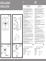
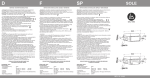
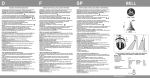
- Wenn der Strahler eingeschaltet ist, stellen Sie sicher, dass der Abstand
zwischen dem Strahler und der zu beleuchtenden Fläche mindestens, wie im Bild 1
angegeben, eingehalten wird.
- Die Leuchte darf nur benutzt werden, wenn die Glasabdeckungen komplett in
Ordnung sind (temperaturwechselbeständiges Sicherheitsglas).
- Sollte eines der beiden Gläser beschädigt sein, bitten Sie den Hersteller umgehend
um ein Ersatzglas.
- Die Leuchte ist für die Wandmontage im Innen-und Aussenbereich geeignet (ta = 25°C).
- Installationshöhe:
egal.
- Montage:
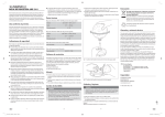
Bereiten Sie die Befestigungslöcher an der Wand vor (2 Löcher Ø 10mm, Tiefe
50mm) und benutzen Sie die mitgelieferten Schraubendübel (siehe Bild 2).
Öffnen Sie die Leuchte, indem Sie die 4 M8 Schrauben lösen.
Halten Sie die Leuchte gegen die Wand , richten sie anhand der Befestigungslöcher
aus und befestigen Sie die Leuchte mithilfe der mitgelieferten Schrauben (Bild 2).
Achtung! Stellen Sie sicher, dass die die beiden Dichtungsgummis die
Befestigungslöcher am Strahler eng abdichten. Achtung! Montieren Sie die Leuchte
nur mit der Kabelverschraubung nach unten.
Setzen Sie die Leuchtmittel ein (FSQ 4-pin).
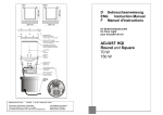
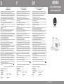
Schliessen Sie die leuchte wieder mit den 4 M8 Schrauben und ziehen Sie sie an
mit min. 8 Nm, stufen- und kreuzweise. (Bild 3).
- Schliessen Sie das 5 adrige Kabel an, wie im Bild 4 beschrieben.
- Beide Leuchtmittel sind in Betrieb, wenn die Leuchte eingeschaltet ist; im
Notlichtfall ist nur das untere Leuchtmittel in Betrieb.
- Um eine einwandfreie Funktion des Notlichtes zu gewährleisten, befolgen Sie bitte
die Herstellerhinweise (Laden der Batterie, periodische Zyklen Laden/Entladen,
Lebensdauer der Batterie, Funktionskontrolle).
- Im Falle, dass es notwendig ist, das Anschlusskabel zu wechseln, lösen Sie die
beiden Schrauben an den beiden Enden des Reflektors, um Zugang zur
elektrischen Versorgungseinheit zu bekommen, lösen Sie das Kabel von der
Anschlussklemme, lösen Sie die Kabelverschraubung und wechseln Sie das Kabel.
Verschrauben Sie den Kabeleinlass wieder fest (PG11 Kabelverschraubung für
Kabeldurchmesser 5÷10mm, schliessen Sie das Kabel wieder an die
Anschlussklemme, unter Beachtung der Polarität, an. Achtung! Beachten Sie den
vordefinierten Abstand zwischen Kabelverschraubung und Reflektor (M6 Nuten).
- Sollte das öffnen der Frontabdeckung problematisch sein, stellen Sie einen
Druckausgleich durch Lösung der PG-Verschraubung her (insbesondere bei
Entladungsleuchtmittel) und ziehen Sie die Kabelverschraubung danach wieder fest an.
- Halten Sie die obere Abdeckung sauber, um einen maximalen Lichtaustritt zu
garantieren und Überhitzung zu vermeiden.
- Leuchte geeignet zur Montage auf normal entflammbaren Oberflächen
Oberflächen.
- Attention! La sécurité du luminaire est garantie seulement avec l'observance
des instructions suivantes, donc il est nécessaire de les conserver.
- Attention! Avant d'exécuter les connexions au réseau, pendant l'assemblage
ou substitution de la lampe, s'assurer d'avoir enlevé tension.
- Pour l'assemblage ou substitution de la lampe, exécuter les instructions
données par le constructeur, jointes à la lampe même.
- Dans l'usage de l'appareil, respecter les distances moindres selon ill. 1.
- L'appareil doit être utilisé seulement s'il est complet de ses écrans de protection
(verres plans trempés).
- Si vous relevez fêlures ou fentes sur un des deux verres, demandez
tout-de-suité au fournisseur un verre de rechange.
- Appareil apte à l'utilisation soit à l'intérieur soit à l'extérieur, monté à paroi (ta= 25°C).
- Hauteur d'installation: n'importe quelle.
- Installation:
Prédisposer les points de fixation à paroi (No.2 trous Ø 10mm longueur 50mm) et
insérer les goujons fournis (voir ill.2).
Ouvrir l'appareil en dévissant les 4 vis Allen M8.
Appuyer l'appareil au mur en corréspondance des trous et le fixer au moyen des
2 vis fournies, ensuite serrer les vis à fond (ill.2).
Attention! S'assurer que les 2 cales en gomme soient dûment positionnés sur le
fond de l'appareil, en corréspondance des trous de fixation.
Attention! Installer l'appareil seulement avec le presse-étoupe tourné en bas.
Insérer les lampes (FSQ 4-pin).
Fermer l'appareil en serrant à fond les 4 vis Allen M8 fournies, avec 8 Nm min.
torque, d'une façon graduelle et croisée (ill.3).
Réunir les terminaux du câble à 5 fils selon ill.4.
Les deux lampes fonctionnent régulièrement quand le réseau est en tension; en
cas d'urgence seulement la lampe qui éclaire vers le bas reste en fonction.
- Pour une utilisation correcte du kit d'urgence voir les instructions fournies par le
constructeur (charge batterie, cycles périodiques de charge et décharge, fin de
vie de la batterie, inhibition).
- Dans le cas où il soit nécéssaire remplacer le câble, dévisser les 2 vis aux
extrémités du réflecteur pour pouvoir accéder à la boîte aux câblages, dételer le
câble de la borne, desserrer le presse-étoupe et remplacer le câble. Serrer à fond
le presse-étoupe (type PG11 pour câble avec Ø 5÷10mm) et réunir encore le
câble à la borne: câbler toujours la ligne d'alimentation aux deux pôles à côté du
fil jaune/vert et la ligne pour la batterie aux deux pôles restants. Attention!
Maintenir la distance entre la plaque et le réflecteur comme donné par les 2
écrous M6.
- Dans le cas où il résulte difficile ouvrir le capot frontal après le fonctionnement,
desserrer le collier du presse-étoupe pour faire entrer un peu d'air dans l'appareil,
ensuite serrer de nouveau le presse-étoupe.
- Nettoyer de temps en temps l'écran supérieur pour assurer le max. rendement
lumineux et éviter problèmes de surchauffage.
- L'appareil est apte au montage sur surfaces normalement inflammables.
- Atención! La seguridad del aparato está garantizada solamente con el uso
apropiado de las siguientes instrucciones, por lo tanto es necesario convervarlas.
- Atención! Antes de realizar las conexiones con la red eléctrica, durante el
montaje o sustitución de la lámpara, recuerde cortar la tensión.
- Para el montaje o sostitución de la lámpara siga las instrucciones del
fabricante suministradas junto con la lámpara.
- En el empleo del aparato, respectsr las distancias mínimas como en fig. 1.
- El aparato tiene que ser utilizado sólo si completo de sus cristales de protección
(vidrios llanos templados).
- En el caso hay rajas o grietas sobre uno de los vidrios, solicitarle directamente
al constructor la parte en sustitución.
- Aparato idóneo al funcionamiento en exteriores y interiores, montado a pared (ta=25°C).
- Altura de instalación: cualquiera.
- Instalación:
Preparar los puntos de fijación a pared (No.2 agujeros Ø 10mm largo 50mm) y
encajar los tornillos de expansión suministrados (fig. 2).
Abrir el aparato destornillando los 4 tornillos Allen M8.
Apoyar el aparato al muro en correspondencia de los agujeros y fijarlo por medio
de los 2 tornillos suministrados, entonces atornillar intensamente (fig.2).
Atención! Cerciorarse que los 2 cauchitos sean bien posicionados sobre el fondo
del aparato, en correspondencia de los agujeros de fijación.
Atención! Instalar el aparato solamente con el prensa-cable hacia el bajo.
Insertar las lámparas (FSQ 4-pin).
Tapar el aparato por medio de los 4 tornillos Allen M8 suministrados, con min.
momento de torsión 8 Nm, de manera progresiva y cruzada (fig.3).
Acoplar los terminales del cable de 5 hilos segùn fig. 4.
- Ambas lámparas funcionan con tension de red ; en caso de emergencia
funciona solamente la lámpara dirigida hacía el basjo.
- Para una corecta utilisación del kit de emergencia respectar las instrucciones
suministradas por el constructor (carga de baterÌa, ciclos periódicos de carga y
descarga, fin de vida batería, inhibición).
- En el caso sea necesario reemplazar el cable, destornillar los 2 tornillos en las
extremidades del reflector para poder acceder al cableo, descablear el cable del
borne, aflojar el prensa-cable y reemplazar el cable. Atornillar intensamente el
prensa-cable (tipo PG11 para cable con Ø 5÷10mm) y acoplar de nuevo el cable
y el borne: cablear siempre la red de alimentación a los 2 polos que se encuentran a los lados del hilo amarillo/verde y la linea de alimentación para la batería a
los 2 otros polos. Atención! Mantener la distancia entre la placa y el reflector
dada por las 2 tuercas M6.
- En caso sea difícil abrir la tapadera anterior después del funcionamiento, aflojar
el cuello del prensa-cable y dejar entrar un poco de aire en el aparato, luego cerrar de nuevo el prensa-cable.
- Limpiar periódicamente el vidrio situado sobre el lado superior para conseguir la
máxima rendición luminosa y evitar el sobrecalentamiento.
- Aparato idóneo al montaje sobre superficies normalmente inflamables.
APPAREIL POUR LAMPES FLUORESCENTES COMPACTES 4-PIN
APARATO DE ILUMINACION PARA LAMPARAS FLUORESCENTES 4 PIN
LEUCHTEN FÜR FLUORESCENT-LEUCHTMITTEL 4 PIN
BASISSERIE: MINSK MIT NOTLICHT
Eigenschaften:
- Anschlussspannung:
230V~
I
- Schutzklasse:
- Lichtleistung:
2x18W FSQ
2x26W FSQ
- Leuchtmittel:
G24q-2
G24q-3
- IP54
- Abmessungen:
195x365x180mm
- Gewicht:
max 7Kg
SÉRIE BASE: MINSK AVEC URGENCE
Caractéristiques:
- Tension d'alimentation:
230V ~
- Classe d'isolement:
I
2x18W FSQ
2x26W FSQ
- Puissance et type de lampe:
- Douille:
G24q-2
G24q-3
- IP54
195x365x180mm
- Dimensions:
- Poids:
max 7Kg
con kit d’emergenza
with emergency kit
DAL 1960
SERIE BASE: MINSK CON EMERGENCIA
Características:
- Tensión de alimentación :
230V ~
- Clase de aislamiento:
I
2x18W FSQ
2x26W FSQ
- Potencia y típo de lámpara:
- Portalámpara:
G24q-2
G24q-3
- IP54
195x365x180mm
- Medidas:
- Peso:
max 7Kg
REV. 00 07/04
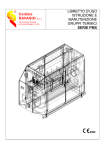
I
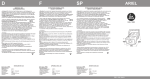
INSTALLAZIONE
INSTALLATION
FSQ
2X26W- 2X18W
min
0,5m
LATO SUPERIORE
UPPER SIDE
min
0,5m
min
0,5m
min
0,5m
LATO INFERIORE
LOWER SIDE
CAVO DI ALIMENTAZIONE
FEEDING CABLE
283 mm
Ø10 mm
95 mm
Fig. 2
Fig. 1
1
4
{
LATO SUPERIORE
UPPER SIDE
RETE INTERROTTA
INTERRUPTED FEED
230V~
{
ordine di serraggio
tightening sequence
1-2-3-4
coppia, torque: 8Nm
230V~
LN
12
3 4
UK
ISTRUZIONI DI INSTALLAZIONE
USO E MANUTENZIONE
INSTALLATION, USE AND
MAINTENANCE INSTRUCTIONS
- Attenzione! La sicurezza dell’apparecchio è garantita solo con l’uso
appropriato delle seguenti istruzioni, pertanto è necessario conservarle.
- Attenzione! Prima di eseguire le connessioni di rete, durante il montaggio o
sostituzione di lampade, assicurarsi di aver tolto la tensione.
- Per il montaggio o sostituzione della lampada, eseguire le istruzioni date dal
costruttore allegate alla lampada stessa.
- Nell' uso dell'apparecchio mantenere le distanze minime come illustrato in fig.1.
- L'apparecchio deve essere utilizzato solo se completo dei suoi schermi di
protezione; trattasi di vetri float temperati.
- Nel caso si osservino incrinature o fessurazioni anche di 1 solo dei 2 vetri
richiedere direttamente al costruttore la parte in sostituzione.
- Apparecchio idoneo all’uso a parete in interni ed esterni (ta=25°C).
- Altezza d'installazione: qualsiasi.
- Installazione:
Predisporre i punti di fissaggio a parete (n°2 fori Ø 10mm lunghezza 50mm) ed
inserirvi i tasselli in dotazione (fig.2).
Aprire l'apparecchio svitando le n°4 viti a brugola M8.
Appoggiare l'apparecchio in corrispondenza dei fori predisposti a parete e fissarlo
tramite le 2 viti in dotazione, serrare a fondo (fig.2).
Attenzione: verificare la presenza dei 2 gommini sul fondo dell'apparecchio
in corrispondenza dei fori di fissaggio.
Attenzione: installare l'apparecchio solo con il pressacavo rivolto verso il basso.
Inserire le lampade (FSQ 4 pin).
Richiudere l'apparecchio serrando a fondo le n°4 viti a brugola M8 con un momento
torcente minimo di 8Nm, applicando un serraggio graduale e incrociato (fig.3).
Cablare i terminali del cavo a 5 fili come indicato in fig.4.
- Entrambe le lampade sono funzionanti nell'utilizzo con tensione di rete ; in
emergenza é accesa una sola lampada (quella rivolta verso il basso).
- Per un corretto utilizzo del kit d'emergenza seguire le istruzioni indicate dal
costruttore stesso (carica batteria, cicli periodici di carica/scarica, fine vita
batteria, inibizione).
- Nel caso in cui vi sia necessità di sostituire il cavo di alimentazione, svitare le 2
viti poste agli estremi del riflettore per avere accesso alla parte elettrica, scablare
il cavo dal morsetto, allentare il pressacavo e sostituire il cavo. Serrare a fondo il
pressacavo (trattasi di PG11 per cavo Ø 5÷10mm) e ricablare il cavo al morsetto:
cablare sempre ai 2 poli ai lati del cavetto giallo/verde la rete di alimentazione e
ai 2 restanti poli la linea per la batteria.
Attenzione: mantenere la distanza tra piastra e riflettore data dai 2 dadi flangiati M6.
- Se si verificano difficoltà di apertura del coperchio anteriore dopo l'utilizzo,
allentare la ghiera del pressacavo per far entrare aria nell'apparecchio e
richiudere immediatamente a fondo il pressacavo.
- Pulire periodicamente il vetro posto sul lato superiore per ottenere la massima
resa luminosa ed evitare il surriscaldamento.
- Apparecchio idoneo al montaggio su superfici normalmente infiammabili.
- Warning! Safety of this fitting is guaranteed only if the following instructions are
properly respected. It is therefore necessary to preserve them.
- Warning! Before connecting to the main network, during positioning or
replacement of lamps, ensure the tension has been disconnected.
- For positioning or replacement of lamps, follow the instructions given by the
lamp's manufacturer, which should be supplied with the lamp itself.
- When the fitting is on, ensure that the minimum distances are respected (pic.1).
- This lighting fitting can be used only if complete of its glass diffusers (float
tempered glasses).
- In case cracks or fissurations are found on either of the two glasses, immediately ask the manufacturer for a spare glass.
- Fitting suitable for indoor and outdoor wall mounting (ta=25°C).
- Height of installation:
any.
- Installation:
Prepare the fixing holes on the wall (No.2 holes Ø 10mm length 50mm) and
embed the screw anchors supplied (see pic.2).
Open the fixture unscrewing the 4 Allen screws M8.
Lean the fixture against the wall, level with the holes, and fix it by means of the 2
screws supplied, then tighten deeply (pic.2).
Warning! Ensure the 2 rubbers are properly fit on the bottom of the fixture, level
with the fixing holes. Warning! Install the fixture only with the cable gland turned
downwards.
Insert the lamps (FSQ 4 pin).
Close the fixture tightening the 4 Allen screws M8 deeply, with 8 Nm min. torque,
in a gradual and crosswise way (pic.3).
Connect the terminals of the 5-wire cable as per pic.4.
Both lamps are "on" when the electrical feeding network is operating;
in emergency, only one lamp is "on" (the downwards lamp).
- For a proper use of the emergency kit follow the instructions given by the
manufacturer (battery load, periodical cycles load/unload, battery end life, rest
mode control).
- In case it will be necessary to replace the feeding cable, unscrew the 2 screws
at the two ends of the reflector, to have access to the electrical gear
compartment, disconnect the cable from the terminal, loosen the cable gland and
replace the cable. Tighten the cable gland deeply (PG11 cable gland for cable
with Ø 5÷10mm) and rewire the cable to the terminal: always connect the feeding
line to the 2 poles at the sides of the yellow/green wire and the battery line to the
2 remaining poles. Warning! Keep the distance between the tray and the reflector
as given by the 2 flanged nuts M6.
- In case it is difficult to open the front cover after use, loosen the ring of the cable
gland to let the air enter the housing then retighten the cable gland deeply.
- Keep the upper glass diffuser clean to ensure the max. light output and avoid
overheating.
- Fixture suitable for installation on normally inflammable surfaces.
APPARECCHI PER LAMPADE FLUORESCENTI COMPATTE 4-PIN
LIGHTING FIXTURE FOR FLUORESCENT LAMPS 4 PIN
RETE NON INTERROTTA
UNINTERRUPTED FEED
BATTERIA, BATTERY
3
SERIE BASE: MINSK CON EMERGENZA
Caratteristiche:
- Tensione di alimentazione :
230V~
- Classe d’isolamento :
I
- Potenza e tipo di lampada :
2x18W FSQ
2x26W FSQ
- Attacco lampada:
G24q-2
G24q-3
- Grado di protezione :
IP 54
195x365x180mm
- Dimensioni:
- Peso:
max 7Kg
GIALLO/VERDE
YELLOW/GREEN
2
LATO INFERIORE
LOWER SIDE
O.R. FROR
CAVO DI ALIMENTAZIONE
FEEDING CABLE
Fig. 3
MINSK
Fig. 4
BASIC SERIES: MINSK WITH EMERGENCY
Characteristics:
- Feeding tension :
230V ~
- Insulation class :
I
2x18W FSQ
2x26W FSQ
- Lamp's type and power:
- Lampholder:
G24q-2
G24q-3
- Protection degree :
IP 54
195x365x180mm
- Dimensions:
- Weight:
max 7Kg