1
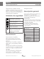
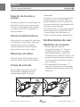
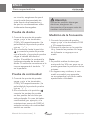
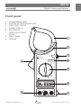
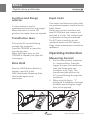
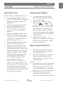
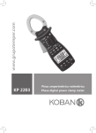
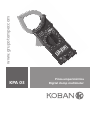
www.grupotemper.com
KPA 03
Pinza amperimétrica
Digital clamp multimeter
KPA 03
Pinza amperimétrica
Índice
Información de seguridad
3
Recomendaciones previas
3
Durante su uso
3
Símbolos de seguridad
4
Mantenimiento
4
Descripción general
4
Selector de función y escala
6
Pinzas transformadoras
6
Retención de datos
6
Tomas de entrada
6
Instrucciones de uso
6
Medición de corriente
6
Prueba de aislamiento
7
Medición de tensión
7
Medición de resistencia
7
Prueba de diodos
8
Prueba de continuidad
8
Medición de la frecuencia
8
Especificaciones
9
Generales
9
Corriente CA
9
Prueba de aislamiento
10
Tensión CA
10
Tensión CC
10
Resistencia
11
Frecuencia
11
Accesorios
11
Cambio de la pila
11
Manual de instrucciones | 2
www.grupotemper.com
KPA 03
Pinza amperimétrica
Información de
seguridad
Esta pinza amperimétrica es un
medidor portátil, con pantalla LCD
de 3 1/2 dígitos con función de
prueba de aislamiento (con opción
de unidad de prueba de aislamiento
de 500V). Ha sido diseñada
de acuerdo con la normativa
IEC1010-1 IEC1010-2-032 relativa a
instrumentos de medida electrónicos
con una categoría de sobretensión
(CAT II 1000V & CAT III 600V)
y un nivel de contaminación 2,
cumpliendo todos los requisitos de
seguridad para pinzas de corriente
portátiles para mediciones y pruebas
eléctricas.
Siga todas las instrucciones de uso
y de seguridad para garantizar que
el dispositivo se usa de un modo
seguro y se mantiene en buenas
condiciones.
Recomendaciones previas
Al usar este medidor, el usuario
deberá observar todas las normas de
seguridad normales referidas a:
• Protección contra daños
provocados por la corriente
eléctrica.
• Protección del medidor frente a un
uso inapropiado.
• El pleno cumplimiento de las
www.grupotemper.com
normas de seguridad solo se
garantiza si se usan las puntas
de prueba suministradas. Si es
necesario, deben ser reemplazadas
por otras del mismo modelo
o por unas con las mismas
especificaciones técnicas.
Durante su uso
Nunca exceda los valores límite
de protección indicados en las
especificaciones para cada rango de
medición.
Cuando el medidor esté conectado
al circuito de medición, no toque
los terminales que no se están
utilizando.
Cuando la escala de valores a medir
sea desconocida de antemano, sitúe
el selector de escala en la posición
más elevada.
Antes de girar el selector de
escala para cambiar de posición,
desconecte las puntas de prueba del
circuito que está probando.
Cuando lleve a cabo mediciones
en TV o circuitos con suministros
cambiantes recuerde siempre que
puede haber un gran abanico de
pulsos de tensión en los puntos
de prueba, que podrían dañar el
medidor.
Manual de instrucciones | 3
KPA 03
Pinza amperimétrica
Tenga siempre cuidado cuando
trabaje con tensiones por encima de
60V CC o 30V CA rms. Mantenga los
dedos por detrás de los límites de la
sonda durante la medición.
Símbolos de seguridad
Precaución: Consulte el
manual de instrucciones.
Tensión peligrosa
Toma de tierra
Doble aislamiento
Este instrumento se pueden
utilizar en corrientes de
tensión consideradas
peligrosas
detergente neutro.
Descripción general
Instrumento válido para mediciones
de tensión CC, corriente AC,
resistencia, pruebas de aislamiento,
continuidad, frecuencia y
temperatura.
Posee protección ante la sobrecarga,
indicador de batería baja e indicador
de exceso de rango.
La siguiente tabla muestra las
funciones que posee esta pinza
amperimétrica.
FUNCIÓN
VCA VCC
•
ACC
•
Ω
•
Mantenimiento
Antes de abrir el medidor,
desconecte siempre las puntas
de prueba de fuente de correinte
eléctrica.
Deje de usar el medidor si observa
algún fallo o anormalidad y llévelo a
revisión.
Nunca use el medidor a menos que
la cubierta trasera y la tapa de la pila
estén en su lugar y completamente
cerradas.
No utilice abrasivos ni disolventes
para limpiar el medidor, utilice
únicamente un paño húmedo y un
Manual de instrucciones | 4
KPA 03
•
•
AISLAMIENTO
•
TEMPERATURA
•
FRECUENCIA
•
www.grupotemper.com
KPA 03
Pinza amperimétrica
Panel frontal
1.
2.
3.
5.
6.
7.
8.
9.
Pinzas transformadoras
Indicador - barrera táctil
Botón de retención de datos
Selector giratorio
de funciones y escalas
Pantalla LCD
Anilla para asa de
muñeca
Tomas de entrada
Gatillo
HOL D
MA X 1 000A ~
C AT l l 1 000V
C AT l ll 6 00V
2 66F C L A MP M E T E R
A~
1000
OFF
WITH 261 OPTION(500V)
INSULA TION TESTER
2000M
EXTERNAL
UNIT
20M Ω
200
Hz
2k
2M
200
200
V~
20
750
2k
1000
200
200
20
V
2
Ω
V~
B AT
CA T ll 6100V
VΩ
COM
EXT
CA T ll
750V~
1000V
MAX
www.grupotemper.com
Manual de instrucciones | 5
KPA 03
Pinza amperimétrica
Selector de función y
escala.
El selector giratorio se utiliza para la
selección de funciones y de escala.
Cuando el interruptor está situado
en la posición OFF, el medidor no
está operativo.
Pinzas transformadoras
Para medir la corriente CA que fluye
a través de un conductor presione
el gatillo para abrir las pinzas
transformadoras, libere el gatillo
para volver a cerrar las pinzas.
Retención de datos
Pulse el botón HOLD para entrar y
salir del modo retención de datos.
Tomas de entrada
Este medidor posee tres tomas
de entrada protegidas contra
sobrecargas hasta los límites
INCORRECTO
Manual de instrucciones | 6
mostrados.
Durante su uso conecte la punta de
prueba negra a la toma COM y la
punta de prueba roja a la toma VΩ.
La toma de prueba roja depende de
la función seleccionada.
Las clavijas EXT se usan para aceptar
los enchufes tipo banana EXT del
comprobador de aislamiento, al
medir la resistencia del aislamiento.
Instrucciones de uso
Medición de corriente
1.Gire el selector hasta la
posición deseada A~. Presione
el gatillo para abrir las pinzas
del transformador y ajustarlas
solamente al conductor (Fig 1). Las
pinzas transformadoras recogerán
la corriente AC que fluye a través
del conductor.
2.Si la pantalla LCD muestra“1”,
hay una situación de sobreescala
y deberá seleccionarse una escala
más alta.
CORRECTO
www.grupotemper.com
KPA 03
Pinza amperimétrica
Prueba de aislamiento
(Unidad de prueba de aislamiento
opciónal de 500 V).
1.Conecte los tres enchufes tipo
banana VΩ, COM y EXT del
comprobador de aislamiento al
medidor VΩ, COM o EXT.
2.Gire el selector de la pinza a la
posición 2000MΩ.
3.Sitúe el selector de escala de la
unidad probadora del aislamiento
en la posición 2000 MΩ.
4.Use el comprobador de aislamiento
de las tomas de prueba, conecte
su entrada L, E a las instalaciones
a probar (La instalación a probar
debe estar apagada).
5.Sitúe el botón de encendido de
la probadora de aislamiento en la
posición ON (encendido).
6.Suelte el pulsador PUSH 500 V;
se encenderá el diodo rojo de
500. La lectura del display del
medidor muestra el valor de la
resistencia de aislamiento. Si la
lectura es inferior a 19 MΩ, cambie
el medidor y el comprobador de
aislamiento a la escala 20 MΩ,
pudiendo así incrementar la
precisión.
7.Si el comprobador de aislamiento
no está en uso, el botón de
encendido deberá estar en la
posición OFF (apagado), y las
tomas de prueba deberán dejarse
en las conexiones de entrada
E, L. Puede incrementarse así la
www.grupotemper.com
duración de la pila y evitar riesgos
de descarga eléctrica.
Medición de tensión
1.Conecte la toma de prueba negra a
la clavija COM y la toma de prueba
roja a la clavija VΩ.
2.Sitúe el interruptor de función en
las posiciones de escala V
oV
y conecte las tomas de prueba
a través de la fuente o carga a
medir. Se indicará la polaridad de
la conexión de la toma roja junto
con el valor del voltaje al realizar la
medición del voltaje de corriente
continua.
3.Si sólo se muestra el signo “1”,
indica una situación de sobreescala
y deberá seleccionarse la escala
más alta.
Medición de resistencia
1.Conecte la toma de prueba negra a
la clavija COM y la toma de prueba
roja a la clavija V/Ω.
2.Sitúe el selector giratorio en la
posición Ω deseada y conecte las
tomas de prueba a través de la
resistencia a medir.
Nota:
1.Si la resistencia a medir excede
el valor máximo de la escala
seleccionada o la entrada no
está conectada, se mostrará una
indicación de sobreescala “1”.
2.Al comprobar la resistencia de
Manual de instrucciones | 7
KPA 03
Pinza amperimétrica
un circuito, asegúrese de que el
circuito está desconectado de
toda fuente de alimentación y
de que los condensadores están
totalmente descargados.
Prueba de diodos
1.Conecte las puntas de prueba
negra y roja a las terminales
COM y VΩ respectivamente. (La
polaridad de la punta de prueba
roja es “+”).
2.Gire el selector hasta la posición
y conecte la punta de prueba
roja al ánodo y la punta de preuba
negra al cátodo del diodo a
probar. El medidor le mostrará la
caída aproximada de tensión del
diodo. Si realiza las conexiones a la
inversa aparecerá el símbolo “1”
en la pantalla.
Prueba de continuidad
1.Conecte las puntas de prueba
negra y roja a las terminales
COM y VΩ respectivamente. (La
polaridad de la punta de prueba
roja es“+”).
2.Gire el selector a la posición
conecte las puntas de prueba
en dos puntos del circuito que
está probando. En caso de haber
continuidad (por ejemplo, si la
resistencia es menor de 100Ω) el
avisador acústico de continuidad
emitirá un sonido.
Manual de instrucciones | 8
Atención
Para evitar posibles descargas
eléctricas, asegúrese de
desconectar el termopar antes de
cambiar a otra función.
Medición de la frecuencia
1.Conecte las puntas de prueba
negra y roja a las terminales COM
y VΩ respectivamente.
2.Coloque el selector en la posición
Hz y conecte las puntas a lo largo
de la fuente o carga que va a
medir.
Nota:
1.Es posible realizar lecturas por
encima de los 10V rms, pero no se
puede garantizar la precisión de las
mismas.
2.En lugares muy ruidosos, si va a
medir una señal muy pequeña,
se recomienda el uso de un cable
apantallado o blindado.
www.grupotemper.com
KPA 03
Pinza amperimétrica
Especificaciones
Se especifica una precisión para un periodo de un año tras la calibración y
18ºC a 28ºC (64ºF a 82ºF) con una humedad relativa inferior al 80%.
Especificaciones generales
Pantalla:
LCD de 3 1/2 digitos, con indicación de
polaridad automática.
Tomas:
1000V CC or 750V CA rms.
Método de medición:
Sistema de convertidor A-D, con
integración de doble pendiente.
Indicación de sobreescala:
La pantalla sólo muestra el signo “1”.
Indicación de polaridad:
La pantalla muestra“-”si la polaridad
es negativa.
Temperatura de funcionamiento: 0 °C a 40 °C (32 °F a 104 °F)
Ambiente de almacenamiento:
-10 °C a 50 °C (14ºF a 122ºF)
Alimentación:
pila alcalina o de carbono de zinc de 9
V (NEDA 1604)
Accesorios:
Manual de instrucciones, conjunto de
puntas de prueba, funda de transporte y
pilas.
Indicación de batería baja:
“BAT” a la izquierda de la pantalla
Accesorios opcionales:
Termopar (tipo K)
Dimensiones:
96x235x46mm
Peso:
330g (pila incluida)
Corriente CA
Escala
Resolución
Precisión
200A
0.1A
±2.5% de lect ±5 digitos
1000A
1A
±3.0% de lect ±10 digitos
Escala de frecuencia: 50Hz a 60Hz
Respuesta: promedio, calibrada en valor eficaz de la onda sinusoidal.
Protección contra sobrecarga: 1200A en 60 segundos.
Capacidad maxilar: Ф50mm
www.grupotemper.com
Manual de instrucciones | 9
KPA 03
Pinza amperimétrica
Prueba de aislamiento
(Unidad de prueba de aislamiento opciónal de 500 V)
Escala
Resolución
Precisión
Nota
20MΩ
1kΩ
±2.0% de lect ±2 digitos
2000MΩ
1MΩ
±4.0% de lect ±2 digitos
< 500MΩ
±5.0% de lect ±2 digitos
>500MΩ
Corriente mínima de medida: 5A
Tensión mínima de medida: 20V
Tensión CA
Escala
Resolución
Precisión
200V
0.1V
±1.0% de lect ±5 digitos
750V
1V
±1.2% de lect ±5 digitos
Impedancia de entrada:>9MΩ en todas las escalas.
Protección contra sobrecarga: 1000V CC o 750V CA en todas las escalas.
Escala de frecuencia: (50Hz a 400Hz) /≤ 600V; (50Hz to 200Hz) / 750V.
Respuesta: promedio, calibrada en valor eficaz de la onda sinusoidal.
Tensión CC
Escala
Resolución
2V
1mV
20V
10mV
200V
0,1V
Precisión
±0.5% de lect ±3 digitos
1000V
1V
±0.8% de lect ±3 digitos
Impedancia de entrada: ≥9M Ω
Protección contra sobrecarga: 250V CA rms para la escala 200mV;
1000V CC o 750V CA para el resto de escalas.
Manual de instrucciones | 10
www.grupotemper.com
KPA 03
Pinza amperimétrica
Resistencia
Escala
Resolución
Precisión
200Ω
0.1Ω
±1.0% de lect ±5 digitos
2kΩ
1Ω
20kΩ
10Ω
200kΩ
100Ω
±1.0% de lect ±8 digitos
2MΩ
1kΩ
Protección contra sobrecarga: 250V CC o 250V CA rms en todas las escalas.
Tensión del circuito abierto: 700mV
Frecuencia
Escala
Resolución
Precisión
2kHz
1Hz
±2.0% de lect ±5 digitos
Accesorios
Suministrados con la pinza:
Punta de prueba moselo T3000
Pila 9V 6F22 o equivalente
Manual de instrucciones
Cambio de la pila
Si aparece el signo “BAT” en la
pantalla, deberá reemplazarse la pila.
Reemplace la pila gastada por una
nueva.
www.grupotemper.com
Atención
Antes de intentar abrir la
carcasa, asegúrese siempre de
que las tomas de prueba se han
desconectado de los circuitos
a medir para evitar un posible
riesgo de descarga eléctrica.
Atención
La utilización de este aparato
en zonas con un campo
electromagnético de radio
frecuencia altamente radiado
(aprox. 3vm) puede influir en la
precisión de las mediciones.
Manual de instrucciones | 11
KPA 03
Digital clamp multimeter
Contents
Safety Information
13
Preliminary
13
During use
13
Symbols
14
Maintenance
14
Description
14
Function and range selection
16
Transformer jaws
16
Data Hold
16
Input Jacks
16
Operating instruction
16
Measuring current
16
Insulation test
17
Measuring voltage
17
Measuring resistance
17
Testing diode
18
Continuity test
18
Measuring frequency
18
Specifications
18
General
19
AC current
19
Insulation test
20
AC voltage
20
DC voltage
20
Resistance
21
Frequency
21
Accesories
21
Battery replacement
21
Instructions manual | 12
www.grupotemper.com
KPA 03
Digital clamp multimeter
Safety information
During Use
The meter is completely portable,
LCD, 3 1/2 digit clamp meter with
insulation test function (with option
500V insulation tester unit).
It has been designed according to
IEC1010-1 IEC1010-2-032 concerning
electronic measuring instruments
with an overvoltage category (CAT II
1000V & CAT III 600V) and pollution
2 and safety requirements for handheld current clamps for electrical
measurement and test.
Never exceed the protection limit
values indicated in specifications for
each range of measurement.
Follow all safety and operating
instructions to ensure that the meter
is used safely and is kept in good
operating condition. For warranty
service, you must present this receipt
with the purchase receipt or invoice.
Preliminary
When using this meter, the user
must observe all normal safety rules
concerning:
• Protection against the dangers
of electronic current.
• Protection of the meter against
misuse.
• Full compliance with safety
standards can be guaranteed
only if used with test leads
supplied. If necessary, they
must be replaced with the same
model or same electronic
www.grupotemper.com
When the meter is linked to
measurement circuit, do not touch
unused terminals.
When the value scale to be
measured is unknown beforehand,
set the range selector at the highest
position. Before rotating the
range selector to change function,
disconnect test leads from the circuit
under test.
When carrying out measurements on
TV or switching power circuits always
remember that there may be high
amplitude voltage pulses at test
points, which can damage the
meter. Never perform resistance
measurements on live circuits.
Always is careful when working with
voltage above 60V dc or 30V ac
rms. Keep fingers behind the probe
barriers while measuring.
Safety Symbols
Important safety information,
refer to the operating manual.
Dangerous voltage may be
present.
Instructions manual | 13
KPA 03
Digital clamp multimeter
Earth ground
Double insulation (Protection
classⅡ)
Application around and
removal from HAZARDOUS
LIVE conductors is permitted
Following table shows function of
the series of clamp meter.
FUNCTION
ACV DCV
•
ACA
•
Ω
•
Maintenance
Before opening the meter, always
disconnect test leads from all sources
of electric current.
If any faults or abnormalities are
observed, the meter can not be used
any more and it has to be checked
out.
Never use the meter unless the back
cover and the battery cover are in
place and fastened fully.
Do not use abrasives or solvents on
the meter, use a damp cloth and mild
detergent only.
KPA 03
•
•
INSULATION
•
TEMPERATURE
•
FREQUENCY
•
General Description
This meter is one of a series portable
3 1/2 digital clamp meter for
measuring DC and AC Voltage, AC
current, resistance, continuity test
and insulation test.
Some models also provide frequency
or temperature test. Full overload
protection. Low battery indication
and over-range indication are
providing.
Instructions manual | 14
www.grupotemper.com
KPA 03
Digital clamp multimeter
Front panel
1.
2.
3.
5.
6.
7.
TRANSFORMER JAWS
BARRIER OR TACTILE INDICATOR
DATA HOLD SWITCH
ROTARY SWITCH
LCD DISPLAY
DROP-PROOF WRIST
STRAP
8. INPUT JACKS
9. TRIGGER
HOL D
MA X 1 000A ~
C AT l l 1 000V
C AT l ll 6 00V
2 66F C L A MP M E T E R
A~
1000
OFF
WITH 261 OPTION(500V)
INSULA TION TESTER
2000M
EXTERNAL
UNIT
20M Ω
200
Hz
2k
2M
200
200
V~
20
750
2k
1000
200
200
20
V
2
Ω
V~
B AT
CA T ll 6100V
VΩ
COM
EXT
CA T ll
750V~
1000V
MAX
www.grupotemper.com
Instructions manual | 15
KPA 03
Digital clamp multimeter
Function and Range
selector
A rotary switch is used to
measurement functions and ranges.
When the switch is set to OFF
position, the meter does not operate.
Transformer Jaws
Pick up the AC current flowing
through the conductor.
Press the TRIGGER to open the
transformer jaws.
When the finger press on the
TRIGGER is released, the jaws will
close again.
Data Hold
Depress HOLD Button Switch to
toggle in and out of the
Data Hold mode. Releasing Data
Hold mode again press
the button.
Instructions manual | 16
Input Jacks
This meter has three input jacks that
are protected against overload to the
limits shown.
During use connect the black test
lead to COM jack and connect red
test lead to V jack. The red test lead
is depended on function selected.
The EXT jack is used for accept
insulation tester unit EXT banana
Plugs, when measurement insulation
resistance.
Operating Instruction
Measuring Current
1. Set the rotary switch at desired
A~ range position. Press the
trigger to open the transformer
jaws and clamp onto one
conductor only (Fig1). The
transformer jaws pick up the
AC current flowing through the
conductor.
2. When only the figure “1”
displayed, it indicates overrange
situation and the higher range
have to be selected.
www.grupotemper.com
KPA 03
Digital clamp multimeter
Insulation Test
Measuring Voltage
(Option 500V insulation tester unit)
1. Connect the insulation tester
unit VΩ, COM, EXT three-banana
plugs to the clamp meter VΩ,
COM, EXT.
2. Set the rotary switch of clamp
meter at 2000MΩ position.
3. Set the insulation tester unit
range switch to the 2000MΩ
position.
4. Uses the insulation tester unit
of the test leads connects its L,
E input connect to being tested
installations. (Test installation’s
must be power OFF)
5. Set the insulation tester power
switch to the ON position.
6. Depress the PUSH 500V pushpush switch; the 500V on red
LED lamp will light. Clamp meter
display reading is the insulation
resistance value. If the reading
is below 19MΩ, change clamp
meter and insulation tester
unit to 20MΩ range, can be
increasing the accuracy.
7. If the insulation tester unit is
not use, the power switch must
shift to power OFF position, and
the test leads must leave the
E. L input connect. That can be
increase battery life and prevent
electrical shock hazard.
1. Connect the black test lead to
the COM jack and the red test
lead to the V jack.
2. Set the rotary switch at the
desired V
or V
range
position and connect test leads
across the source or load under
measurement. The polarity of
the red lead connection will be
indicated along with the voltage
value when making DC voltage
measurement.
3. When only the figure“ 1 ”is
displayed, it indicates overrange
situation and the higher range
has to be selected.
www.grupotemper.com
Measuring Resistance
1. Connect the black test lead to
the COM jack and the red test
lead to the V jack.
2. Set the rotary switch at desired
Ω position and connect test
leads across the resistor under
measurement.
Note:
1. If the resistance being measured
exceeds the maximum value of
the range selected or the input
is not connected, an overrange
indication“1”will be displayed.
2. When checking in - circuit
resistance, be sure thecircuit
under test has all power removed
Instructions manual | 17
KPA 03
Digital clamp multimeter
Testing Diode
Measuring Frequency
1. Connect the black test lead to
the COM jack and the red test
lead to the V jack. (The polarity
of red lead is“ + ”)
2. Set the rotary switch at
position and connect red
lead to the anode, black lead
to the cathode of the diode
under testing. The meter will
show the approx. forward
voltage of the diode. If the lead
connection is reversed, only
figure“1”displayed.
1. Connect the black test lead to
the COM jack and the red test
lead to the V jack.
2. Set the rotary switch at Hz
position and connect test leads
across the source or load under
measurement.
Continuity Test
1. Connect the black test lead to
the COM jack and the red test
lead to the V jack. (The polarity
of the red lead is positive“ + ”)
2. Set the rotary switch at
position and connect test leads
across two points of the circuit
under testing. If continuity
exists (i.e., resistance less than
about100 ), built -in buzzer will
sound.
NOTE:
1. Reading is possible at input
voltage above 10V rms. but the
accuracy is not guaranteed.
2. In noisy environment, it is
preferable to use shield cable for
measuring small signal.
Specifications
Accuracy is specified for a period of
one year after calibration and at 18°C
to 28°C (64°F to 82°F) with relative
humidity to 80%.
WARNING
To avoid electric shock, be sure the
thermocouple has been removed
before changing to another
function measurement.
Instructions manual | 18
www.grupotemper.com
KPA 03
Digital clamp multimeter
Specifications
GENERAL
Display:
3 1/2 digit LCD,
with automatic polarity indication
Terminals and earth ground:
1000V dc or 750V rms ac (sine)
Measuring Method:
Dual-slope integration A-D converter
Overrange Indication:
“1” Figure only in the display
Polarity indication:
“-” displayed for negative polarity
Operating Temperature:
0°C to 40°C (32°F to 104°F)
Storage Environment:
-10°C to 50°C (14°F to 122°F)
Power:
9V alkaline or carbon-zinc battery
(6F22 or equivalent )
Accessories:
Operating manual ,set of test leads
Low Battery Indication:
“BAT” to left of display
Optional Accessories:
Thermocouple ( K type )
Dimension:
96(W) X 235(D) X 46(H) mm
Weight:
330g( including battery )
AC CURRENT
RANGE
RESOLUTION
ACCURACY
200A
0.1A
±2.5% of rdg ±5 digits
1000A
1A
±3.0% of rdg ±10 digits
Frequency Range: 50Hz to 60Hz
Response: Average, Calibrated in rms of sine wave
Overload protection: 1200A within 60 seconds. Jaw Opening:
Ф50mm
www.grupotemper.com
Instructions manual | 19
KPA 03
Digital clamp multimeter
INSULATION TEST
RANGE
(With option 500V insulation tester unit)
RESOLUTION
ACCURACY
NOTE
20MΩ
1kΩ
±2.0% of rdg ±2 digits
2000MΩ
1MΩ
±4.0% of rdg ±2 digits
< 500MΩ
±5.0% of rdg ±2 digits
Minimum measurement current : 5A
Minimum measurement voltage : 20V
>500MΩ
AC VOLTAGE
RANGE
RESOLUTION
ACCURACY
200V
0.1V
±1.0% of rdg ±5 digits
750V
1V
±1.2% of rdg ±5 digits
Input Impedance: 9M on all ranges
Overload protection: 1000V DC or 750V AC on all ranges
Frequency Range:(50Hz to 400Hz) /≤ 600V;
(50Hz to 200Hz) / 750V.
Response: Average, calibrated in rms of sine wave
DC VOLTAGE
RANGE
RESOLUTION
2V
1mV
20V
10mV
200V
0,1V
ACCURACY
±0.5% of rdg ±3 digits
1000V
1V
±0.8% of rdg ±3 digits
Input Impedance: ≥9M Ω
Overload protection: 250Vrms AC for 200mV range,
1000V DC or 750V AC for other range.
Instructions manual | 20
www.grupotemper.com
KPA 03
Digital clamp multimeter
RESISTANCE
RANGE
RESOLUTION
ACCURACY
200Ω
0.1Ω
±1.0% of rdg ±5digits
2kΩ
1Ω
20kΩ
10Ω
200kΩ
100Ω
±1.0% of rdg ±8digits
2MΩ
1kΩ
Overload protection: 250V DC or 250Vrms AC on all ranges.
Open circuit voltage: 700mV
FREQUENCY
RANGE
RESOLUTION
ACCURACY
2kHz
1Hz
±2.0% of rdg ±5digits
Accessories
COME WITH THE CLAMP METER
Test Leads Model: T3000
Battery 9V 6F22 or equivalent
Operation Manual
Battery Replacement
If the sign“BAT”appears on the
LCD display, it indicates that battery
should be replaced. Remove the
battery cover of case.
Replace the exhausted battery with a
new one.
www.grupotemper.com
WARNING
Before attempting to open the
battery cover, be sure that test
leads have been disconnected from
measurement circuits to avoid
electric shock hazard.
WARNING
Using this appliance in an
environment with a strong radiated
radio-frequency electromagnetic
field (approximately 3V/m) may
influence its measuring accuracy.
Instructions manual | 21
KPA 03
Digital clamp multimeter
Instructions manual | 22
www.grupotemper.com
GARANTÍA • WARRANTY
GARANTIE • GARANTIA
2
años
years
années
anos
TEMPER ENERGY INTERNATIONAL S.L.
garantiza este aparato por 2 años ante
todo defecto de fabricación. Para hacer
válida esta garantía, es imprescindible
presentar con este resguardo el ticket o
factura de compra.
TEMPER ENERGY INTERNATIONAL
S.L. garantit cet apareil pour le durée
de 2 annèes contre tout défault de
fabrication. Pour le service de garantie,
vous devez présenter ce reçu avec du
ticket de caisse ou la facture.
TEMPER ENERGY INTERNATIONAL S.L.
guarantees this device during 2 years
against any manufacturing defect. For
warranty service, you must present this
receipt with the purchase receipt or
invoice.
TEMPER ENERGY INTERNATIONAL S.L.
garantía este aparelho contra defeitos
de fábrica ate 2 anos. Para o serviço
de garantia, você deve apresentar este
recibo com o recibo de compra ou
fatura.
Ref. Art.
Nº serie / Serial number
Nombre / Name / Nom / Nombre
Fecha de venta / Date of purchase
Date de vente / Data de venda
Sello establecimiento vendedor / Dealer stamp
Cachet du commercant / Cambo da firma
TEMPER ENERGY INTERNATIONAL S.L.
Polígono industrial de Granda, nave 18
33199 • Granda - Siero • Asturias
Teléfono: (+34) 902 201 292
Fax:
(+34) 902 201 303
Email:
[email protected]
Una empresa
del grupo