1
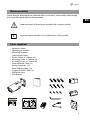
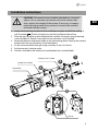
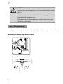
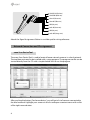
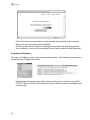
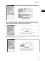
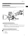
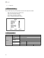
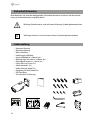
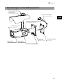
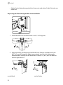
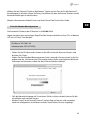
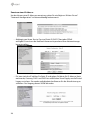
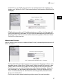
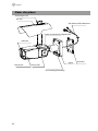
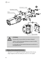
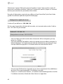
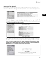
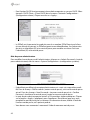
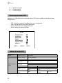
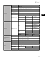
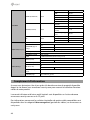
EN
DE
FR
Quick Installation Guide
1/3” Network Camera, WDR,
Day&Night, 1920x1080, 5.151mm PoE, Infrared, 10x AF
Zoom
PXB-2280Z10 D
Table of content
Notes on safety ..............................................................................................................3
Parts supplied ................................................................................................................3
Part names ......................................................................................................................4
Installation instructions ................................................................................................5
Pan & Tilt adjustments......................................................................................................................................................6
Power supply connections..............................................................................................................................................7
Network Connection and IP assignment...................................................................................................................8
eneo Scan Device Tool.................................................................................................................................................8
Quick Network Setup ..................................................................................................................................................9
Operating instructions ................................................................................................13
Using OSD controller..................................................................................................................................................... 13
Description of the joystick operation........................................................................................................ 13
Description of the ZOOM&FOCUS adjustment ..................................................................................... 13
OSD menu startup.......................................................................................................................................................... 14
OSD menu table.............................................................................................................................................................. 14
Further information .....................................................................................................16
2
Notes on safety
Please also pay attention to the enclosed safety instructions, and carefully read through
this instruction guide before initial operation.
EN
Important points of warning are marked with a caution symbol.
i
Important points of advice are marked with a notice symbol.
Parts supplied
•
•
•
•
•
•
•
•
•
•
•
•
•
Network Camera
Operating Instruction
Mounting Template
Cable Signal Sticker
Plastic Anchor: 6 x 30mm (4x)
Mounting Screw: 4 x 30mm (4x)
Assembly Screw: 4 x 14mm (4x)
Torque Wrench: 3mm (1x)
Wiring Connector: (1x)
Video Sub-out Cable (1x)
Coupler for RJ45 Cable (1x)
EMI Ferrite Core
Easy Bracket
3
Part names
Sunshield bolt
Sunshield
Ethernet & Power cable
OSD setup control cover
Dual window
Bracket
Front case
Rear case
Lock/unlock screw
4
Easy bracket
Installation instructions
CAUTION: The camera’s base should be attached to a structural
object, such as concrete, hard wood, wall stud or ceiling rafter
that supports the weight of the camera. If necessary use appropriate mounting material (e.g. anchors) instead of the material
enclosed with the camera.
EN
1. Locate the mounting template at the installation position and drill the ceiling or
wall if needed. i The easy bracket can not be installed on the ceiling.
2. Place the easy bracket on pre-drilled position and fix it through using mounting
screws(4x30mm). Skip this step when an easy bracket is not installed.
3. Route the ethernet and power cable to the connecting place. Hook up the camera
bracket with the easy bracket as illustrated below.
4. Fix the camera bracket through using assembly screws (4x14mm).
5. Set the camera’s viewing angle.
6. Put the sunshield to the camera unit and tighten the sunshield-bolts.
Mounting Screw 1: 4x30mm
Assembly Screw: 4x14mm
Torque Wrench
1
2
4
3
Cable exit
5
CAUTION:
Extreme care should be taken NOT to scratch the window in front
of lens.
Care should be taken the cable is NOT to be damaged, kinked or
exposed in the hazardous area.
Do not expose the camera directly to a strong light source such
as the sun or spot light.
Pan & Tilt adjustments
• Unlock the screw on the camera bracket through using the torque wrench supplied
• Set the camera’s viewing angle then lock the screw on the bracket.
Adjustment of viewing angle with a bracket
Lock/Unlock Screw
Torque wrench
1. Pan limit: Pan is limited to +/- 90°.
90°
6
90°
2. Tilt limit: Tilt is limited to 0°(2°) min ~ 90° max. for wall(ceiling) installation respectively with reference to the wall(ceiling) when the inclination of camera module is
0°, that is, the image is aligned horizontally.
EN
90°
on the wall 88°
on the ceiling
3. Inclination limit (Horizontal image alignment): Inclination limited to +/-90° max.
±90°
Power supply connections
Make sure the power is removed before the installation. Camera can work with either
24VAC or 12VDC, dual voltage power and PoE (IEEE Std. 802.3af ). Primary and secondary
grounds are completely isolated to avoid the possible ground loop problems.
1. Plug the network cable into RJ-45 Ethernet Port. If PoE is the unique power, there
will be no need to connect Power terminal.
2. When DC12V or AC24V Local power is necessary, connect the low voltage (DC12V
or AC24V) first, then plug the AC adapter to AC outlets to avoid an improper reset
from power jitter and a damage from the surge voltage when no load.
i When PoE and local dual power are connected at the same time, local power has
priority.
7
AC24V/DC12V (Red wire)
AC24V/GND (Black wire)
Alarm-IN (Green wire)
Alarm-OUT (Blue wire)
GND (Gray wire)
Audio-IN (Brown wire)
GND (Gray wire)
Audio-OUT (Orange wire)
Attach the Signal Assignment Sticker in a visible spot for wiring reference.
Network Connection and IP assignment
eneo Scan Device Tool
The eneo Scan Device Tool is used to locate all eneo network cameras in a local network.
The tool does not need to be installed with a setup program. The program exe-file can be
started directly from the CD with a simple double click to use the program.
After pushing the button „Find eneo devices“ you will get a list of cameras connected to
the local network. Highlight your camera in the list and open a context menu with a click
of the right mouse button.
8
EN
Select the „Editing the camera IP address“ option to open a window for setting the cameras IP properties. When you are done click the „Activate“ button to update the camera
settings.
For further information, please refer to the eneo Scan Device Tool Quick Start Guide.
Quick Network Setup
The network camera‘s default IP address is: 192.168.1.10.
Therefore, to access the camera for the first time, set the PC‘s address as 192.168.1.XX; for
example:
IP Address: 192.168.1.20
Subnet Mask: 255.255.255.0
• Enter the camera’s IP address in the URL bar of the Web browser window and hit
“Enter.”
• Enter the default user name (root) and password (root) in the prompt request
dialogue. It is also possible to reset IP parameters to the original factory default
settings by pressing the IP reset.
9
• If the Information message doesn‘t come out due to the problems like network
failure, you can start the manual installation.
• Click the Install ActiveX Control, and the pop-up window will be displayed. After
the installation is successfully completed, Smart Viewer window will be displayed.
Assigning an IP address
To assign an IP address to the camera proceeded as follows: Click Network Configuration
on the Network Configuration menu.
• Depending on the service type, the network configuration can be in any of Static
IP, DHCP Client, or PPPoE. You need to set up the network camera according to your
network type.
10
EN
• For static IP, select static IP and input values for IP address, NetMask, Gateway,
DNS1, DNS2 and click apply for saving settings. After apply, program will ask closing web browser for updates, which will take 20~30 seconds.
• For DHCP, DHCP server must exist in the same network environment. Select DHCP
Client from Network Configuration, click Apply.
11
• PPPoE is used to connect IP products to PPPoE modem provided by ISP. Since
PPPoE needs verification, ID and password are necessary to access network. Type in
ID and password.
Administrator password
To change the password for the administrator, click Admin Password on System Configuration menu.
• Default ID for admin account is fixed as “root” and not allowed to change. In Old
Password field, enter the current password. In both New Password and Confirm
Password fields, enter the same new password.
• The password must be between 4 and 23 alphanumeric letters. Click Apply to put
it into effect. Because you have replaced the password with a new one, the existing
network connection made with old password now is lost.
• You will have to reconnect for using the new password.
12
Operating instructions
Using OSD controller
Setup menu can be accessed and controlled by OSD control joy stick on the side of camera unit. Five commands are available with the joy stick.
Standard SD Card Slot
IP Reset
Cover Open
OSD Control Joy Stick
Video Sub-out Connector
Description of the joystick operation
1. MENU Key (●) : Access to the menu or enter the setting.
2. UP/DOWN Key (▲/▼) : Choose the desired sub-menu and to move the cursor up or
down.
3. LEFT/RIGHT Key (◄/►) : Set up the value of the selected menu. Used to adjust the
desired menu selection and to move the cursor left or right.
Description of the ZOOM&FOCUS adjustment
i Works only when OSD Menu is inactive and IP is not connected.
1. ▲ : Zoom In
2. ▼ : Zoom Out
3. ◄ : Focus Near
13
EN
4. ► : Focus Far
OSD menu startup
Press ‘●’ (OSD menu Joy stick key) down to access the setup menu mode.
•
•
•
•
EXIT : Exits the setup menu without save.
SAVE : Saves the menu settings.
DFLT : Reset to the factory defaults.
BACK : Go back to the previous menu.
/'07
<11/(1%75
':21574'
9*+6'$#.
+/#)'
+06'..+)'0%'
52'%+#.(70%
&+52.#;
=':+6?
=5#8'?
=&(.6?
OSD menu table
MAIN MENU
ZOOM/FOCUS
SUB MENU
CONFIGURATION
FOCUS
AUTO, ONE PUSH, MANUAL
DISTANCE
0.1m, 1.0m, 3.0m, 5.0m, 10.0m
ZOOM SPEED
0~7
LENS REFRESH
E.ZOOM
ZOOM PRESET
HOME POSITION
14
ONE PUSH
1DAY~10DAYS
OFF/ON
max. x2~x19, x21, x23, x25, x28, x32
PRESET
1~4
MODE
OFF, ON
OFF/ON
DWELL TIME
3sec~60sec
EXPOSURE
MODE
AUTO/ IRIS.P/ SHUT.P/ MANUAL
AGC
OFF/ON (0~10)
SHUT SPEED
30/25fps]
x4, x2, 1/30(25), 1/60(50), 1/120(100), 1/250~1/30,000sec
IRIS
0~20
DSS
30/25fps] OFF/ x2, x4
FLICKERLESS
OFF/ON
BRIGHTNESS
0~20
EN
OFF
BACK LIGHT
WDR
LEVEL
MID-HIGH, HIGH, LOW,
MID-LOW,MIDDLE
BLC
POSITION, SIZE
0~20
HLC
LEVEL, COLOR
0~13
DELAY
0~255sec
THRS
0~28
GAP
LOW, MID-LOW, MIDDLE,
MID-HIGH, HIGH
IR DETECTION
OFF, ON
IRDET LEVEL
LOW, MID-LOW, MIDDLE,
MID-HIGH, HIGH
BURST
OFF, ON
DELAY
0~255sec
BURST
OFF, ON
POLARITY
ACTIVE LOW, ACTIVE HIG
BURST
OFF, ON
AUTO
EXPOSURE
DAY&NIGHT
EXT-IN
DAY
NIGHT
WHITE BAL
IMAGE
MODE
AUTO, ONE PUSH, MANUAL, INDOOR, OUTDOOR
RED GAIN
0~20 (control only in MANUAL mode)
BLUE GAIN
0~20 (control only in MANUAL mode)
CHROMA
0~20
DNR
OFF, LOW, MIDDLE, HIGH, AUTO
MIRROR
OFF, H, V, H&V
SHARPNESS
0~10
ACE
OFF, LOW, MIDDLE, HIGH
DEFOG
OFF/ON
FREEZE
OFF, ON
GAMMA
0.45/ 0.55/ 0.65/ 0.75
MODE
AUTO, MANUAL
LEVEL
LOW, MIDDLE, HIGH
15
PRIVACY
OFF/ON
INTELLIGENCE
MASK
1~24
MODE
OFF, ON
POSITION
SIZE
COLOR
0~13
TRANS
0~4
SIZE
MOTION
DIS
OFF/ON
OFF/ON
INTERVAL
0~255
DWELL TIME
0~255
ZOOM PRESET
OFF, ON
RANGE
10%, 20%, 30%
FILTER
LOW, MIDDLE, HIGH
AUTO C
OFF, Half, Full
DEFECT
FULL
IMAGE RANGE
COMP
SYSTEM
NTSC or PAL
HD FORMAT
1080p /30(25)fps
COMM
ID, BAUD RATE, PROTOCOL
SPECIAL FUNC
USER
DISP SEL
LEVEL (0~32)
OFF
ON
ID, TITLE, ZOOM RATIO, SYSTEM MSG
SET TITLE
DISPLAY
INIT SEL
OFF
ON
ID, BAUDRATE, PROTOCOL, VERSION, INIT MSG
SET INIT MSG
LANGUAGE
ENGLISH, Simplified CHINESE, Traditional CHINESE, JAPANESE
Further information
Make sure to always upgrade to the latest firmware version available from the eneo website at www.eneo-security.com to receive the latest functionality for your product.
The manual, and other software tools are available on the eneo website at www.eneo-security.com or on the included CD.
Information on compatible video management software solutions can be found in the
category Videomanagement at www.eneo-security.com.
16
Table of content
Sicherheitshinweise .....................................................................................................18
Lieferumfang ................................................................................................................18
Bezeichnungen von Gerätekomponenten ................................................................19
Installationsanweisungen ...........................................................................................20
Einstellung von Schwenkung und Neigung.......................................................................................................... 21
Stromversorgungsanschlüsse..................................................................................................................................... 23
Netzwerkverbindung und IP-Zuweisung............................................................................................................... 24
eneo Scan Device Tool.............................................................................................................................................. 24
Schnelle Netzwerkkonfiguration ......................................................................................................................... 25
Betriebsanleitung ........................................................................................................28
Bildschirmmenü-Steuerung verwenden................................................................................................................ 28
Beschreibung der Joystick-Bedienung...................................................................................................... 28
Beschreibung der Zoom- & Fokus-Einstellung ...................................................................................... 28
Bildschirmmenü starten............................................................................................................................................... 29
Bildschirmmenü-Übersicht.......................................................................................................................................... 29
Weitere Informationen ................................................................................................31
17
DE
Sicherheitshinweise
Bitte beachten Sie auch die beiliegenden Sicherheitshinweise und lesen Sie diese Anleitung vor Inbetriebnahme sorgfältig durch.
Wichtige Warnhinweise sind mit einem Achtung-Symbol gekennzeichnet.
i
Wichtige Hinweise sind mit einem Hinweis-Symbol gekennzeichnet.
Lieferumfang
• Netzwerk Kamera
•Betriebsanleitung
•Bohrschablone
•Kabelsignal-Aufkleber
• Kunststoffdübel: 6 x 30mm (4x)
• Befestigungsschraube: 4 x 30mm (4x)
• Montageschraube: 4 x 14mm (4x)
• Inbusschlüssel: 3mm (1x)
• Steckverbinder: (1x)
• Video Sub-out Kabel (1x)
• Kupplung für RJ45 Kabel (1x)
• EMI Ferritkern
• "Easy Bracket"-Halterung
18
Bezeichnungen von Gerätekomponenten
Bolzen für Sonnenschutzdach
Sonnenschutzdach
Ethernet- und Stromkabel
DE
Abdeckung für Bildschirmmenüsteuerung
Doppelglasiges Fenster
Kamerahalter
Vorderes Gehäuse
“Easy Bracket”-Halterung
Hinteres Gehäuse
Schraube zum Verriegeln/Entriegeln
19
Installationsanweisungen
ACHTUNG: Die Kamerahalterung sollte an einem Bauelement
wie etwa Beton, Hartholz, einem Wandständer oder Deckenbalken befestigt werden, welches das Gewicht der Kamera trägt.
Verwenden Sie, falls erforderlich, geeignetes Befestigungsmaterial (z.B. Dübel) anstelle des mitgelieferten Materials.
1. Halten Sie die Bohrschablone an die Installationsstelle und bohren Sie die Löcher
in Decke oder Wand, falls erforderlich. i Die „Easy Bracket”-Halterung kann nicht
an der Decke angebracht werden.
2. Setzen Sie die “Easy Bracket”-Halterung an die Stelle mit den vorgebohrten
Löchern und befestigen Sie sie mit den Befestigungsschrauben (4 x 30 mm).
Überspringen Sie diesen Schritt, wenn keine „Easy Bracket”-Halterung angebracht
werden soll.
3. Verbinden Sie das Ethernet- und Spannungsversorgungskabel mit den jeweiligen
Anschlüssen. Befestigen Sie den Kamerahalter an der „Easy Bracket”-Halterung
wie unten abgebildet.
4. Befestigen Sie den Kamerahalter mit den Montageschrauben (4 x 14mm).
5. Stellen Sie den Betrachtungswinkel der Kamera ein.
6. Setzen Sie das Sonnenschutzdach auf die Kameraeinheit auf und ziehen Sie die
Bolzen für das Sonnenschutzdach fest.
20
Befestigungsschraube 1: 4 x 30mm
Montageschraube: 4 x 14mm
1
2
4
Inbusschlüssel
DE
3
Kabeldurchgang
ACHTUNG:
Achten Sie besonders darauf, das Fenster vor dem Objektiv
NICHT zu verkratzen.
Es muss sorgfältig darauf geachtet werden, das Kabel NICHT zu
beschädigen, zu knicken oder Gefahrenbereichen auszusetzen.
Setzen Sie die Kamera nie direkt einer starken Lichtquelle wie der
Sonne oder einem Scheinwerfer aus.
Einstellung von Schwenkung und Neigung
• Lösen Sie die Schraube am Kamerahalter mit dem mitgelieferten Inbusschlüssel.
21
• Stellen Sie den Betrachtungswinkel der Kamera ein und ziehen Sie die Schraube am
Halter fest.
Anpassung des Betrachtungswinkels mit einem Halter
Inbusschlüssel
Schraube zum
Verriegeln/Entriegeln
1. Schwenkwinkel: Der Schwenkwinkel ist auf +/- 90° begrenzt.
90°
90°
2. Neigungswinkel: Die Neigung ist bei Wand- (bzw. Decken)-Installation auf min.
0°(2°) bis max. 90° begrenzt, wobei vorausgesetzt wird, dass die Neigung des
Kameramoduls in Bezug auf die Wand (bzw. Decke) 0° ist, d.h., dass das Bild horizontal ausgerichtet ist.
90°
an der Wand 22
88°
an der Decke
3. Drehwinkel (horizontale Bildausrichtung): Der Drehwinkel ist begrenzt auf max.
+/-90°.
±90°
DE
Stromversorgungsanschlüsse
Stellen Sie vor der Installation sicher, dass die Spannungszufuhr unterbrochen ist. Die
Kamera kann entweder mit 12VDC oder 24VAC, doppelte Spannungsversorgung und
PoE (IEEE Std. 802.3af ) betrieben werden. Primäre und sekundäre Masse sind vollständig
voneinander isoliert, um mögliche Probleme durch Erdungsschleifen zu vermeiden.
1. Schließen Sie das Netzwerkkabel am RJ-45 Ethernet-Port an. Wenn PoE als einzige
Stromquelle verwendet wird, muss die Netzklemme nicht angeschlossen werden.
2. Wenn eine lokale Stromversorgung mit 12VDC bzw. 24VAC notwendig ist, schließen Sie zuerst die Niederspannungsleitung (12VDC bzw. 24VAC) an und stecken
Sie erst danach das Netzteil in die Steckdose, um fehlerhafte Resets aufgrund
von Spannungsschwankungen und Beschädigungen durch Überspannung bei
Lastfreiheit zu vermeiden.
i Wenn PoE und eine lokale duale Stromversorgung gleichzeitig verbunden sind, hat
die lokale Stromversorgung Vorrang.
AC24V/DC12V (rotes Kabel)
AC24V/GND (schwarzes Kabel)
Alarmeingang (grünes Kabel)
Alarmausgang (blaues Kabel)
GND (schwarzes Kabel)
Audioeingang (braunes Kabel)
GND (schwarzes Kabel)
Audioausgang (orangenes Kabel)
Bringen Sie den Signalbelegungs-Aufkleber an einer sichtbaren Stelle als Referenz für die
Anschlussverkabelung an.
23
Netzwerkverbindung und IP-Zuweisung
eneo Scan Device Tool
Mit dem eneo Scan Device Tool können alle eneo Netzwerk Kameras in einem lokalen
Netzwerk lokalisiert werden. Das Tool muss nicht mit einem Setup Programm installiert
werden. Die exe-Datei des Programms kann mit einem Doppelklick direkt von der CD
gestartet und benutzt werden.
Nach dem Drücken des Buttons „eneo Geräte suchen“ erhalten Sie eine Liste der mit dem
lokalen Netzwerk verbundenen Kameras. Markieren Sie Ihre Kamera in der Liste und
öffnen Sie ein Kontextmenü durch Klicken der rechten Maustaste.
24
Wählen Sie die „Kamera IP Adresse bearbeiten“ Option um ein Fenster für die Kamera IPEinstellungen zu erhalten. Wenn Sie fertig sind, klicken Sie den „Aktivieren“ Button um die
Kameraeinstellungen zu aktualisieren.
Weitere Informationen finden Sie im eneo Scan Device Tool Quick Start Guide.
DE
Schnelle Netzwerkkonfiguration
Die Standard-IP-Adresse der IP-Kamera ist: 192.168.1.10.
Legen Sie daher beim erstmaligen Zugriff auf die Kamera die Adresse Ihres PCs im Bereich
192.168.1.XX fest. Zum Beispiel:
IP-Adresse: 192.168.1.20
Subnetzmaske: 255.255.255.0
• Geben Sie die IP-Adresse der Kamera in die URL-Leiste des Browser-Fensters und
drücken Sie "Enter".
• Geben Sie den Standard-Benutzernamen (root) sowie das Passwort (root) in die Eingabemaske ein. Sie können die IP-Parameter auch auf die ursprünglichen Werkseinstellungen zurücksetzen, indem Sie den IP-Reset-Schalter drücken.
• Falls die Benachrichtigung auf Grund eines Fehlers nicht erscheint, können Sie die
Installation auch manuell starten.
• Klicken Sie auf "Install ActiveX Control" und ein Pop-up Fenster wird angezeigt.
Nach der erfolgreichen Installation wird das Smart Viewer Fenster angezeigt.
25
Zuweisen einer IP-Adresse
Um der Kamera eine IP-Adresse zuzuweisen, gehen Sie wie folgt vor: Klicken Sie auf
"Netzwerk-Konfiguration" im Netzwerkkonfigurationsmenü.
• Abhängig von Ihrem Service Typ sind Static IP, DHCP Client oder PPPoE
verfügbar. Sie müssen die Netzwerk Kamera entsprechend Ihrer Netzwerkumgebung einstellen.
• Für eine statische IP wählen Sie Static IP und geben Sie Werte für IP-Adresse, Netzwerkmaske, Gateway, DNS1 und DNS2 ein und klicken Sie auf Apply um die Einstellungen zu sichern. Sie werden aufgefordert den Browser für die Aktualisierung zu
schließen. Der Vorgang dauert 20-30 Sekunden.
26
• Für DHCP muss ein DHCP Server bereits in der gleichen Netzwerkumgebung vorhanden sein. Wählen Sie DHCP Client unter Network Confi guration und klicken Sie
auf Apply.
DE
• PPPoE wird verwendet, um IP-Produkte mit einem vom ISP zur Verfügung gestellten PPPoE-Modem zu verbinden. Da für PPPoE eine Identifizierung erforderlich ist,
benötigen Sie ID und Passwort um auf das Netzwerk zugreifen zu können. Geben
Sie Ihre ID und Passwort ein.
Administrator Passwort
Um das Administrator Passwort zu ändern klicken Sie im Systemkonfigurationsmenü auf
Admin Password.
• Die Standard ID für den Administrator Account ist auf „root“ festgelegt und kann nicht
geändert werden. Geben Sie im "Old Password" Feld das aktuelle Passwort ein. In den
Feldern „New Password“ und „Confirm Password“ geben Sie das neue Passwort ein.
• Das Passwort muss aus 4 bis 23 alphanumerischen Zeichen bestehen. Klicken Sie
auf "Anwenden", um die Änderungen anzuwenden. Durch das Ändern des Passworts ist die bestehende, mit dem alten Passwort hergestellte, Netzwerkverbindung nun unterbrochen.
• Sie müssen nun eine neue Verbindung mit dem neuen Passwort herstellen.
27
Betriebsanleitung
Bildschirmmenü-Steuerung verwenden
Zugriff und Steuerung des Konfigurationsmenüs können über den Joystick zur Bildschirmmenü-Steuerung an der Kamera und einen Service Monitor erfolgen. Fünf Befehle
stehen mit dem Joystick zur Verfügung.
Standard SD-Karten-Schlitz
IP Reset
Abdeckung öffnen
Joystick zur Bildschirmmenü-Steuerung
Video Sub-out Anschluss
Beschreibung der Joystick-Bedienung
1. MENÜ-Taste (●): Zum Zugreifen auf das Menü oder Eingeben der Einstellung.
2. UP/DOWN-Taste (▲/▼): Zum Wählen des gewünschten Untermenüs und zum
Bewegen des Cursors nach oben oder nach unten.
3. LEFT/RIGHT-Taste (◄/►): Zum Anpassen eines Werts im ausgewählten Menü. Dient
zum Auswahl eines gewünschten Menü-Elements und um den Cursor nach links
oder rechts zu bewegen.
Beschreibung der Zoom- & Fokus-Einstellung
i Funktioniert nur, wenn das Bildschirmmenü inaktiv ist und keine IP-Verbindung
besteht.
28
1.
2.
3.
4.
▲ : Heranzoomen
▼ : Herauszoomen
◄ : Fokus nah
► : Fokus fern
DE
Bildschirmmenü starten
Halten Sie die Taste '●' (Taste für Bildschirmmenü-Joystick) gedrückt, um in das SetupMenü zu gelangen.
•
•
•
•
EXIT: Verlassen des Setup-Menüs ohne zu speichern.
SAVE: Speichern der Menüeinstellungen.
DFLT : Zurücksetzen auf die Werkseinstellungen.
BACK : Zum vorherigen Menü gehen.
/'07
<11/(1%75
':21574'
9*+6'$#.
+/#)'
+06'..+)'0%'
52'%+#.(70%
&+52.#;
=':+6?
=5#8'?
=&(.6?
Bildschirmmenü-Übersicht
MAIN MENU (HAUPTMENÜ)
ZOOM/FOCUS
SUB MENU
CONFIGURATION
FOCUS
AUTO, ONE PUSH, MANUAL
DISTANCE
0,1 m, 1,0 m, 3,0 m, 5,0 m, 10,0 m
ZOOM SPEED
0-7
LENS REFRESH
E.ZOOM
ZOOM PRESET
HOME POSITION
ONE PUSH
1 DAY - 10 DAYS
OFF/ON
max. x2-x19, x21, x23, x25, x28, x32
PRESET (Voreinstellung)
1-4
MODUS
OFF, ON
OFF/ON
DWELL TIME
3 Sek. - 60 Sek.
29
EXPOSURE
MODUS
AUTO/ IRIS.P/ SHUT.P/ MANUAL
AGC
OFF/ON (0-10)
SHUT SPEED
30/25fps]
x4, x2, 1/30(25), 1/60(50), 1/120(100), 1/250~1/30,000 Sek.
IRIS
0-20
DSS
30/25fps] AUS/ x2, x4
FLICKERLESS (FLIMMERFREI) OFF/ON
BRIGHTNESS (Helligkeit)
0-20
OFF (AUS)
BACK LIGHT
(Gegenlichtkompensation)
WDR
LEVEL (Stufe)
MID-HIGH, HIGH, LOW,
MID-LOW, MIDDLE
BLC
POSITION, SIZE
0-20
HLC
LEVEL, COLOR
0-13
DELAY (Verzögerung):
0- 255 Sek.
THRS
0-28
GAP
LOW, MID-LOW, MIDDLE,
MID-HIGH, HIGH
IR DETECTION
OFF, ON
IRDET LEVEL
LOW, MID-LOW, MIDDLE,
MID-HIGH, HIGH
BURST
OFF, ON
DELAY (Verzögerung):
0- 255 Sek.
BURST
OFF, ON
POLARITY
ACTIVE LOW, ACTIVE HIGH
BURST
OFF, ON
AUTO
EXPOSURE
DAY&NIGHT
EXT-IN
DAY
NIGHT
WHITE BAL (Weißabgleich)
IMAGE
30
MODUS
AUTO, ONE PUSH, MANUAL, INDOOR, OUTDOOR
RED GAIN
0-20 (Einstellung nur im MANUAL-Modus möglich)
BLUE GAIN
0-20 (Einstellung nur im MANUAL-Modus möglich)
CHROMA
0-20
DNR
OFF, LOW, MIDDLE, HIGH, AUTO
MIRROR (Spiegeln)
OFF, H, V, H&V
SHARPNESS (Schärfe)
0-10
ACE
OFF, LOW, MIDDLE, HIGH
DEFOG
OFF/ON
FREEZE
OFF, ON
GAMMA
0,45 / 0,55 / 0,65 / 0,75
MODUS
AUTO, MANUAL
LEVEL (Stufe)
LOW, MIDDLE, HIGH
PRIVACY (Bereichsmaske)
OFF/ON
INTELLIGENCE
(Spezialfunktionen)
MASK
1~24
MODUS
OFF, ON
POSITION
SIZE
COLOR (Farbe)
0-13
TRANS
0-4
DE
SIZE
MOTION
DIS
OFF/ON
OFF/ON
INTERVAL
0-255
DWELL TIME
0-255
ZOOM PRESET
OFF, ON
RANGE (Bereich)
10 %, 20 %, 30 %
FILTER
LOW, MIDDLE, HIGH
AUTO C
OFF, Half, Full
DEFECT
FULL
IMAGE RANGE
COMP
SYSTEM
NTSC oder PAL
HD FORMAT
1080p /30(25)fps
COMM
ID, BAUD RATE, PROTOCOL
SPECIAL FUNC
BENUTZER
DISP SEL
LEVEL (0-32)
OFF (AUS)
ON (EIN)
ID, TITLE, ZOOM RATIO, SYSTEM MSG
SET TITLE
DISPLAY (Anzeige)
INIT SEL
OFF (AUS)
ON (EIN)
ID, BAUDRATE, PROTOCOL, VERSION, INIT MSG
SET INIT MSG
LANGUAGE (Sprache)
ENGLISH, Simplified CHINESE, Traditional CHINESE, JAPANESE
Weitere Informationen
Bitte halten Sie die Firmware stets aktuell, damit Sie die neuesten Funktionen des Geräts
nutzen können. Die aktuellsten Firmware-Versionen finden Sie auf unserer Website unter
www.eneo-security.com.
Das Benutzerhandbuch und weitere Software-Tools sind auf der eneo Website unter
www.eneo-security.com oder auf der mitgelieferten CD verfügbar.
Informationen zu kompatiblen Video Management Software-Lösungen finden Sie in der
Kategorie Videomanagement unter www.eneo-security.com.
31
Table of content
Consignes de sécurité..................................................................................................33
Matériel livré.................................................................................................................33
Noms des pièces...........................................................................................................34
Instructions d'installation............................................................................................35
Réglages Panoramique/Inclinaisons........................................................................................................................ 36
Connexions d'alimentation......................................................................................................................................... 38
Connexion au réseau et attribution d’une adresse IP........................................................................................ 39
eneo Scan Device Tool (outil de balayage d´eneo)........................................................................................ 39
Configuration rapide du réseau............................................................................................................................ 40
Mode d'emploi..............................................................................................................43
Utilisation d'une commande OS................................................................................................................................ 43
Description du fonctionnement de la manette de contrôle................................................................ 43
Description de l'adaptation de ZOOM & FOCUS...................................................................................... 43
Démarrage du menu OSD............................................................................................................................................ 44
Tableau du menu OSD................................................................................................................................................... 44
Complément d'information.........................................................................................46
32
Consignes de sécurité
Respectez les consignes de sécurité ci-après et lisez attentivement cette notice avant
toute utilisation.
Les mises en garde importantes sont précédées d´un symbole
d´avertissement.
i
FR
Les points importants sont précédés d´un symbole de notice.
Matériel livré
•
•
•
•
•
•
•
•
•
•
•
•
•
Caméra de réseau
Mode d'emploi
Gabarit de perçage
Étiquette de signalisation du câble
Chevilles en plastique : 6 x 30 mm (4x)
Vis de fixation : 4 x 30 mm (4x)
Vis de montage : 4 x 14 mm (4x)
Clé Torx : 3 mm (1x)
Connecteur de câblage : (1x)
Câble de sous-sortie vidéo (1x)
Coupleur pour câble RJ45 (1x)
Noyau en Ferrite EMI
Support de fixation Easy Bracket
33
Noms des pièces
Boulon du pare-soleil
Pare-soleil
Câble Ethernet & câble d'alimentation
Couvercle de commande de configuration OSD
Double vitre
Support
Panneau avant
Panneau arrière
Vis de verrouillage/déverrouillage
34
Easy bracket
Instructions d'installation
ATTENTION : La base de la caméra doit être fixée à une surface
solide, co mme du bois dur, un mur, pilier ou poutre au plafond
apte à supporter le poids de la caméra dôme. Si nécessaire,
utiliser un matériel de fixation (ancrages) plus adéquat au lieu du
matériel fourni avec la caméra.
1. Placer le gabarit de montage à la position de montage et faire un trou dans le
plafond ou dans le mur si nécessaire. i Le support „Easy Bracket“ ne peut pas
être fixé au plafond.
2. Placer le support Easy bracket sur la position pré-forée et fixer à l´aide des vis de
montage (4 x 30 mm). Si Easy bracket n'est pas installé, cette étape du processus
d'installation est ignorée.
3. Guider les câbles Ethernet et d'alimentation vers le lieu de connexion. Connecter le support de la caméra avec Easy Bracket comme le montre l'illustration
ci-dessous.
4. Fixer la camera au plafond en utilisant deux vis (4 x 14 mm).
5. Réglage de l'angle de vision de la caméra.
6. Installer le pare-soleil sur la caméra, puis serrer les boulons du pare-soleil.
35
FR
Vis de montage 1 : 4 x 30 mm
Vis de montage : 4 x 14 mm
1
2
4
Clé Torx
3
Sorties de câbles
ATTENTION :
Il faudra veiller à ne pas érafler la vitre devant l'objectif.
Veillez à ne PAS endommager, déformer ou exposer le câble
dans une zone dangereuse.
La caméra doit pas être exposée directement au soleil ou à un
éclairage fluorescent.
Réglages Panoramique/Inclinaisons
• Dévisser la vis sur le support de la caméra à l'aide de la clé Torx fournie
• Régler l'angle de vision de la caméra, puis serrer la vis sur le support.
36
Réglage de l'angle de vision à l'aide d'un support
FR
Vis de verrouillage/
déverrouillage
Clé Torx
1. Limite de panoramique : le panoramique est limité à +/- 90°.
90°
90°
2. Limite d'inclinaison : l’inclinaison est limitée à une fourchette de 0° (2°) min ~ 90°
max. pour une installation murale (au plafond) par rapport au plafond lorsque
l’inclinaison du module caméra est à 0°, c’est-à-dire lorsque l’image est alignée
horizontalement.
90°
Montage mural 88°
Montage plafond
37
3. Limite d'inclinaison (alignement horizontal de l'image) Inclinaison limitée à +/-90°
max.
±90°
Connexions d'alimentation
Assurez-vous que l´alimentation secteur est déconnectée avant l'installation. La caméra
peut fonctionner en 24 V CA ou en 12 V CC ainsi qu’avec une alimentation bitension et
par PoE (IEEE Std. 802.3af ). Les mises à la terre primaire et secondaire sont complètement
isolées pour éviter les éventuels problèmes de boucle de masse.
1. Brancher le câble réseau dans la prise RJ-45 Ethernet. Quand le PoE est l'unique
alimentation en courant, il ne sera pas nécessaire de connecter le terminal de
courant.
2. Si un courant CC 12 V ou CA 24 V local est requis, connectez d'abord le connecteur
basse tension (CC 12 V ou CA 24 V), puis l'adaptateur CA aux sorties de courant
alternatif afin d'éviter une réinitialisation inopportune due à une instabilité de
l'alimentation et des dommages en cas de surtension sans charge.
i Quand le PoE et la l'alimentation en bitension sont connectés simultanément, le courant local est prioritaire.
CA24V/CC12V (câble rouge)
CA24V/GND (câble noir)
Alarm-IN (Câble vert)
Alarm-OUT (Câble bleu)
GND (Câble gris)
Audio-IN (Câble brun)
GND (Câble gris)
Audio-OUT (Câble orange)
Apposer l'étiquette de l'affectation de signal en un lieu visible pour référence de câblage.
38
Connexion au réseau et attribution d’une adresse IP
eneo Scan Device Tool (outil de balayage d´eneo)
L´outil de balayage d´eneo est utilisé pour localiser toutes les caméras réseau dans le
réseau local. Un programme d´installation n´est pas nécessaire pour installer cet outil Le
programme exe.file peut être démarré directement du CD avec un double clic.
Après avoir appuyé sur le bouton "Find eneo devices" (trouver le dispositif eneo), vous
pourrez prendre connaissance de la liste des caméras connectées au réseau local. Sélectionner votre caméra dans la liste et ouvrir le menu contextuel en cliquant avec le bouton
droit de la souris.
39
FR
Sélectionner l´option "Editing the camera IP address" (taper l´adresse de la caméra IP)
pour ouvrir une fenêtre et rentrer l´adresse IP. Quand vous avez fini, cliquer sur "activate"
(activer) pour actualiser les paramètres de la caméra.
Pour plus d´informations, merci de vous référer au Scan Device Tool Quick Start Guide
(guide d´installation rapide du dispositif de balayage).
Configuration rapide du réseau
L´adresse IP par défaut est : 192.168.1.10.
Dès lors, pour la première utilisation de la caméra, saisissez cette adresse dans l´ordinateur : 192.168.1.XX; par exemple :
Adresse IP : 192.168.1.20
Masque de sous-réseau : 255.255.255.0
• Saisissez l'adresse IP de la caméra dans la barre des URL du navigateur, puis appuyez sur « Entrée ».
• Saisissez l'identifiant par défaut (root) et le mot de passe par défaut (root) dans la
boîte de dialogue. Il est également possible de réinitialiser les paramètres IP originaux par défaut en appuyant sur le commutateur de réinitialisation de l'IP.
• Si le message d’information n’apparaît pas en raison notamment d’une défaillance
du réseau, vous pouvez procéder à l’installation manuelle.
• Cliquez sur « Install ActiveX Control », et la fenêtre contextuelle apparaîtra. Une fois
l´installation terminée, la fenêtre du Smart Viewer va apparaître.
40
Attribution d´une adresse IP
Pour attribuer une adresse IP à la caméra, veuillez procéder comme suit : Cliquez sur «
Network Configuration » (Configuration réseau) dans le menu « Network Configuration ».
FR
• En fonction du type de service, la configuration réseau peut être soit « Static IP » (IP
statique), « DHCP Client » (Client DHCP), ou PPPoE. Vous devez configurer la caméra
réseau en fonction de votre type de réseau.
• En cas d’utilisation d’une adresse IP statique, sélectionnez « Static IP » et saisissez
les valeurs de l’adresse IP, du masque de sous-réseau, de la passerelle ainsi que le
DNS1 et le DNS2. Cliquez ensuite sur « apply » (appliquer) pour enregistrer votre
configuration. Le programme vous invitera alors à fermer le navigateur Web pour
procéder à une mise à jour qui durera de 20 à 30 secondes.
41
• Pour l’option DHCP, l’environnement réseau doit comporter un serveur DHCP. Sélectionnez « DHCP Client » (Client DHCP) dans le menu « Network Configuration »
(Configuration réseau). Cliquez ensuite sur « Apply ».
• Le PPPoE sert à connecter les produits eneo à un modem PPPoE fourni par le fournisseur d’accès à Internet. Le PPPoE exigeant une authentification, il est nécessaire
de saisir un identifiant (ID) et un mot de passe pour accéder au réseau. Saisissez
l´identifiant (ID) et le mot de passe.
Mot de passe administrateur
Pour modifier le mot de passe de l’administrateur, cliquez sur « Admin Password » (mot de
passe administrateur) dans le menu « System Configuration » (configuration système).
• L’identifiant par défaut du compte administrateur est « root » et ne peut être modifié. Dans le champ « Old Password » (ancien mot de passe), saisissez le mot de passe
actuel. Dans les champs « New Password » (nouveau mot de passe) et « Confirm
Password » (confirmer le mot de passe), tapez le nouveau mot de passe.
• Le mot de passe doit comporter entre 4 et 23 caractères alphanumériques. Cliquez
sur le bouton « Apply » (appliquer) pour l’appliquer.. Étant donné que vous avez
remplacé le mot de passe par un nouveau, la connexion réseau, établie à l’aide de
l’ancien mot de passe, est à présent perdue.
• Vous devrez vous connecter à nouveau à l’aide du nouveau mot de passe.
42
Mode d'emploi
Utilisation d'une commande OS
Le menu de configuration peut être consulté et contrôlé soit en utilisant la manette de
contrôle de l'affichage à l'écran situé sur le côté de la caméra. Cinq fonctions de commande sont disponibles avec la manette.
FR
Logement Carte SD standard
IP Reset
Couvercle ouvert
Manette de commande OSD
Connecteur sous-sortie vidéo
Description du fonctionnement de la manette de contrôle
1. Touche MENU (●) : Accès au menu ou saisie du paramètre.
2. Touche HAUT/BAS (▲/▼) : Sélection du sous-menu et déplacement du curseur vers
le haut ou le bas.
3. Touche GAUCHE/DROIT (◄/►) : Réglage de la valeur du menu sélectionné. Elle sert
à adapter la sélection du menu et à déplacer le curseur vers la gauche ou la droite.
Description de l'adaptation de ZOOM & FOCUS
i Fonctionne uniquement quand le menu OSD Menu est inactif et aucune adresse IP
n'est connectée.
1. ▲ : Agrandissement
43
2. ▼ : Rétrécissement
3. ◄ : Focus proche
4. ► : Focus éloigné
Démarrage du menu OSD
Appuyer sur '●’(touche de la manette du menu OSD) pour accéder au mode de menu
configuration.
•
•
•
•
EXIT : Quitter le menu de configuration sans sauvegarder.
SAVE : Pour quitter le menu des paramètres.
DFLT : initialisation aux réglages d’usine.
BACK : Retour au menu principal.
/'07
<11/(1%75
':21574'
9*+6'$#.
+/#)'
+06'..+)'0%'
52'%+#.(70%
&+52.#;
=':+6?
=5#8'?
=&(.6?
Tableau du menu OSD
MAIN MENU (menu
principal)
ZOOM/FOCUS (Zoom/mise
au point)
SUB MENU (sous-menu)
CONFIGURATION
FOCUS (mise au point)
AUTO, ONE PUSH, MANUAL
DISTANCE
0.1m, 1.0m, 3.0m, 5.0m, 10.0m
ZOOM SPEED (vitesse de la
mise au point)
0~7
LENS REFRESH (actualisation PULSATION
de l'objectif)
1DAY~10DAYS (1 jour - 10 jours)
E.ZOOM
OFF/ON
max. x2~x19, x21, x23, x25, x28, x32
ZOOM PRESET (préréglage
zoom)
PRESET (préréglage)
1~4
MODE
OFF, ON
OFF/ON
DWELL TIME (durée de
maintien)
HOME POSITION (position
initiale)
44
3 sec~60 sec
EXPOSITION
MODE
AUTO/ IRIS.P/ SHUT.P/ MANUAL
AGC
OFF/ON (0~10)
SHUT SPEED (vitesse de
l'obturateur)
30/25 fps]
x4, x2, 1/30(25), 1/60(50), 1/120(100), 1/250~1/30,000 sec
IRIS
0~20
DSS
30/25 fps] OFF/ x2, x4
FLICKERLESS
(anti-scintillement)
OFF/ON
BRIGHTNESS (luminosité)
0~20
FR
OFF
BACK LIGHT (contre-jour)
WDR
LEVEL (niveau)
MID-HIGH, HIGH, LOW,
MID-LOW,MIDDLE
BLC
POSITION, SIZE (position,
taille)
0~20
HLC
LEVEL, COLOR (niveau,
couleur)
0~13
DELAY (retard)
0~255 sec
THRS
0~28
GAP
LOW, MID-LOW, MIDDLE,
MID-HIGH, HIGH
IR DETECTION (détection IR)
OFF, ON
IRDET LEVEL (niveau IRDET)
LOW, MID-LOW, MIDDLE,
MID-HIGH, HIGH
BURST (salve)
OFF, ON
DELAY (retard)
0~255 sec
BURST (salve)
OFF, ON
POLARITY (polarité)
ACTIVE LOW, ACTIVE HIG
BURST (salve)
OFF, ON
AUTO
EXPOSITION
DAY&NIGHT (jour & nuit)
EXT-IN
DAY (jour)
NIGHT (nuit)
WHITE BAL (balance des
blancs)
IMAGE
MODE
AUTO, ONE PUSH, MANUAL, INDOOR, OUTDOOR
RED GAIN (acquisition de
rouge)
0~20 (contrôle uniquement en mode MANUAL)
BLUE GAIN (acquisition
de bleu)
0~20 (contrôle uniquement en mode MANUAL)
CHROMA
0~20
DNR
OFF, LOW, MIDDLE, HIGH, AUTO
MIRROR (MIROIR)
OFF, H, V, H&V
SHARPNESS (netteté)
0~10
ACE
OFF, LOW, MIDDLE, HIGH
DEFOG (désembuage)
OFF/ON
FREEZE (figer)
OFF, ON
GA mmA
0.45/ 0.55/ 0.65/ 0.75
MODE
AUTO, MANUAL
LEVEL (niveau)
LOW, MIDDLE, HIGH
45
PRIVACY (Confidentialité)
OFF/ON
MASQUE
1~24
MODE
OFF, ON
POSITION
SIZE (taille)
COLOR (couleur)
0~13
TRANS
0~4
SIZE (taille)
INTELLIGENCE
MOTION (mouvement)
DIS
OFF/ON
OFF/ON
INTERVAL (intervalle)
0~255
DWELL TIME (durée de
maintien)
0~255
ZOOM PRESET (préréglage
zoom)
OFF, ON
RANGE (plage)
10%, 20%, 30%
FILTER (filtre)
LOW, MIDDLE, HIGH
AUTO C
OFF, Half, Full
DEFECT (défaut)
SPECIAL FUNC (fonct. spéc.)
IMAGE RANGE (plage de
l'image)
FULL
COMP
USER (utilisateur)
LEVEL (niveau) (0~32)
SYSTEM (système)
NTSC ou PAL
HD FORMAT (format HD)
1080p /30(25) fps
COMM
ID, BAUD RATE, PROTOCOL (ID, taux de baud, protocole)
DISP SEL (sél. aff.)
OFF
MARCHE
ID, TITLE, ZOOM RATIO, SYSTEM MSG
SET TITLE (configurer titre)
DISPLAY (Affichage)
INIT SEL (sél. init.)
OFF
MARCHE
ID, BAUDRATE, PROTOCOL, VERSION, INIT MSG
SET INIT MS (config. mess.
init.)G
LANGUAGE (langue
ENGLISH, Simplified CHINESE, Traditional CHINESE, JAPANESE (anglais, chinois simplifié,
chinois traditionnel, japonais)
Complément d'information
Assurez-vous de toujours être à jour grâce à la dernière version du progiciel disponible
depuis le site d'eneo sous www.eneo-security.com pour recevoir les dernières fonctionnalités de votre produit.
Le manuel utilisateur et d’autres outils logiciels sont disponibles sur le site web eneo
www.eneo-security.com ou sur le CD joint.
Des informations concernant les solutions logicielles de gestion vidéo compatibles sont
disponibles dans la catégorie Videomanagement (gestion des vidéos) sur www.eneo-security.com.
46
FR
47
eneo® is a registered trademark of
VIDEOR E. Hartig GmbH
Exclusive distribution through specialised
trade channels only.
VIDEOR E. Hartig GmbH
Carl-Zeiss-Straße 8
63322 Rödermark/Germany
Tel. +49 (0) 6074 / 888-0
Fax +49 (0) 6074 / 888-100
www.videor.com
www.eneo-security.com
Technical changes reserved
© Copyright by VIDEOR E. Hartig GmbH
Version 06/2015


![[B40] RWS-TE2PAFZ39-IR(Videor)](http://vs1.manualzilla.com/store/data/005979657_1-986d79b0350f507a65bc366834e972e4-150x150.png)