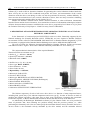
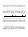
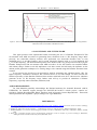
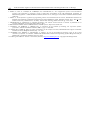
1
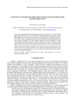
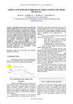
SISOM & ACOUSTICS 2014, Bucharest 22-23 May
ON THE ACCELERATION REGIMES OF A THOMSON LINEAR MOTION ACTUATOR
USED AS VIBRATIONS GENERATOR IN THE 1-3 HZ FREQUENCY RANGE
Dan N. DUMITRIU, Cornel LALA, Daniel BALDOVIN
Institute of Solid Mechanics of the Romanian Academy, Str. Constantin Mille, nr. 15, 010141 Bucharest, Romania
E-mail: [email protected], [email protected]
Abstract: This paper presents technical aspects concerning the use of a Danaher Thomson linear
motion actuator to generate vibrations in the 1-3 Hz frequency range. The purpose is to include such a
ball screw drive electrical actuator in a dynamic car simulator, the role of the linear actuator being to
reproduce/generate the low frequencies vertical vibrations of the driver seat. The actuator is
controlled in position (“position mode”), but in fact the limitations of the actuator in
acceleration/deceleration (maximum acceleration/deceleration of 167 cm/s2) and its limitations in
velocity (maximum velocity of 42 cm/s) have a significant influence on the generated motion profile.
The actuator is controlled offline and without charge, further work will implement a real time control
and will study the influence on the motion profile generation technique of a ≈100 kg charge to be
actuated using this Danaher Thomson linear actuator.
Keywords: Danaher Thomson linear motion electrical actuator, ball screw drive, control in position,
acceleration regimes, maximum velocity, vertical vibrations.
1. INTRODUCTION
The intensive level of technology achieved nowadays requires an increased technological knowledge.
In order to reinforce this technological knowledge, the role of technical/technological papers is to reinforce
the connection between scientific papers and the technological need to simply control a (mechanical)
device/motion in a correct manner. This technical paper shows how desired linear motion vibrations in the 13 Hz frequency range can be achieved using a Danaher Thomson linear actuator with ball screw drive [1],
taking into account its limitations in what concerns the maximum velocity and acceleration.
In what concerns linear motion actuators, the electrical actuators are not traditionally recommended as
vibrations generators, compared with hydraulic or pneumatic actuators which are widely used for generating
vibrations, providing a (very) fast response. Nevertheless, important technological improvements have been
lately performed, thus electrical linear motion actuators can nowadays be considered as replacements for
hydraulic and pneumatic cylinders, based on the simplicity of electrical operation, on their greater accuracy,
etc. For example, it is more economical to install and maintain electrical actuators than pneumatic/hydraulic
ones, the pneumatic/hydraulic system including additional components such as compressors, piping, filters,
etc [2]. So, electrical precision linear actuators benefit from cleaner, simpler and more energy-efficient
power transmission, being also less noisy than hydraulic or pneumatic actuators [1]. As electric devices, they
are much easier to integrate with modern programmable controls, being naturally well-suited for use in realtime systems, in conjunction with feedback control [3]. In what concerns the life expectancy of electrical
actuators with ball screw drives, there are still advances to be made, current research trying to increase the
performance of ball screw drives in correlation with the associated tribological and wear processes in such
linear rolling guidance systems [4-6].
The ball screw drive electrical actuator will be used to generate vibrations in the 1-3 Hz frequency
range, corresponding more or less to the vertical vibrations to be induced under the seat driver of a dynamic
car simulator. Full car dynamics computer simulations have been intensively studied for many years, thus the
vertical displacements and accelerations of the seat driver can be easily obtained [7]. In our case, CARSIM
189
On the acceleration regimes of a Thomson linear motion actuator used as vibrations generator in the 1-3 Hz range
software [8] is used as full car dynamics simulator for generating the vertical vibrations induced under the
driver seat by the car ride on the considered road profile. Of course, real measurements of the vertical
vibrations under the driver seat during car rides can also be performed if necessary, without difficulty. In
what concerns the transmission of seat (vertical) vibrations to driver, there are many researches simulating
seat suspension dynamics and the effect on ride comfort [10,11].
Besides the Danaher Thomson linear motion electrical actuators or other well-known international
brands of linear motion electrical actuators, let us remind the existence of a Romanian technological solution
of linear electromechanical actuators with ball/roller screw drives, proposed by Prof. Năsui et al [5,6] from
the Technical University of Cluj-Napoca – North University Centre of Baia Mare.
2. DESCRIPTION OF DANAHER THOMSON LINEAR MOTION ELECTRICAL ACTUATOR
WITH BALL SCREW DRIVE
In the framework of a national project PN-II-PT-PCCA-2011-3.1-0190, financially supported by the
National Authority for Scientific Research (ANCS, UEFISCDI), we have acquired a Danaher Thomson
servoactuator ECT90, called ECT09 B43R02PB 3220 0400 TN 02 in Danaher Motion designation [1]. This
servoactuator is equipped with a Danaher Motion Kollmorgen servodrive AKD-P00306-NBCN-E000.
We will use below the following shortened denomination: Danaher Thomson ECT90 servoactuator
with AKD servodrive. Figure 1 shows such a Danaher Thomson parallel B43 AC servo motor [1].
The main mechanical characteristics of the acquired Danaher
Thomson ECT90 servoactuator are [1]:
• Stroke (Smax) = 400 mm = 40 cm;
• Speed up to 420 mm/s = 42 cm/s;
• Maximum load = 1800 N.
• Profile size (w×h): 90 × 92 mm;
• Screw type: BALL SCREW;
• Screw diameters: 32 mm;
• Screw leads: 20 mm;
• Repeatability: ± 0,05 mm;
• Motor style: PARALLEL;
• Gear box: BELT GEAR;
• Motor type: BRUSHLESS AC SERVO MOTOR;
• Motor designation: AKM53K-CNCNR-00 (Kollmorgen);
• Motor feedback: RESOLVER;
• Motor connection: CONNECTOR;
• Motor BRAKE (24Vdc);
• Lubrication: SINGLE POINT LUBRICATION.
Figure 1 – Danaher Thomson parallel B43 AC
servo motor [1].
The lifetime expectancy of such a ball screw drive device is a function of many important factors,
including load, speed, duty cycle, ambient temperature and screw type [1]. In order to increase as much as
possible this lifetime expectancy, this paper tries to draw some conclusions concerning the operational
acceleration regimes, so that to minimize the mechanical shocks and thus the wear of the ball screw.
As indicated by the Kollmorgen WorkBench software [12], the “Motion Tasks” are to be provided in
terms of positions. But, when attaining one position starting from the previous position, i.e., when
performing the elementary task k, the user must specify the maximum allowed velocity for task k (has to be ≤
42 cm/s which is the maximum velocity attainable by the drive motion) and the maximum allowed
D.N. Dumitriu, C. Lala, D. Baldovin
190
acceleration and respectively deceleration during task k (has to be ≤ 167 cm/s2 which is the maximum
acceleration/ deceleration attainable by the drive motion).
So, we can say that the actuator is controlled in position (“position mode”), but in fact the limitations of
the actuator in acceleration (maximum acceleration/deceleration of 167 cm/s2) and its limitations in velocity
(maximum velocity of 42 cm/s) have a significant influence on the generated motion profile. In fact, the
control in position is more or less what we need in order to reproduce in a dynamic car simulator the vertical
displacements of the driver seat, corresponding to a real drive (in our case simulated using CARSIM).
3. DANAHER THOMSON ECT90 SERVOACTUATOR WITH AKD SERVODRIVE, USED AS
VIBRATIONS GENERATOR IN THE 1-3 HZ FREQUENCY RANGE
Table 1 shows the “Motion Tasks” for a successive motion between +5cm and –5cm, with a maximum
allowed velocity during tasks of 42 cm/s (maximum attainable velocity by our Danaher Thomson ECT90
servoactuator with AKD servodrive) and a maximum allowed acceleration/deceleration during tasks of
100 cm/s2 (less than the maximum attainable of 167 cm/s2). In what concerns the acceleration profile, the
trapezoidal profile has been used so far, being simpler and more appropriate for our need to reproduce a
vibratory vertical displacement. Further work will test also the OneToOne/S-Curve profile.
Table 1 – Kollmorgen WorkBench “Motion Tasks” for a sinusoidal vibration with A1 = 5cm amplitude and f 1 = 1.264 Hz frequency.
Task
no.
1
2
Position [cm]
5.0
–5.0
Velocity
[cm/s]
42.0
42.0
Acceleration
[cm/s2]
100.0
100.0
Deceleration
[cm/s2]
100.0
100.0
(acceleration)
Profile
Trapezoidal
Trapezoidal
Following
task
2
1
The actuator is controlled offline by the AKD servodrive. The tests presented in this paper are
performed without charge/load. Further work will study the influence on the motion profile generation
technique of a ≈100 kg charge to be actuated by this Danaher Thomson linear actuator.
Figure 2a shows the vertical linear displacement of the drive when performing the “motion tasks”
described in Table 1, i.e., a successive motion between +5cm and –5cm, with a maximum allowed velocity
during tasks of 42 cm/s and a maximum allowed acceleration/deceleration during tasks of 100 cm/s2. More
precisely, the position feedback PL.FB is shown, being identical with the position command PL.CMD,
especially due to the fact that the tests are performed without any load. Moreover, PL.FB is almost identical
with the sinosidal profile given by:
xtest 1 = A1 sin ( 2πf1 t + ϕ0,1 ) = 5.0 ⋅ sin ( 2π ⋅1.264 ⋅ t + ϕ0,1 ) [cm].
(1)
The (oscillo)scope of the Kollmorgen WorkBench software is providing us the following
“commanded” digital signals: postion command PL.CMD, velocity command VL.CMD and the acceleration
command denoted by IL.CMDACC. The scope provides also the following feedback signals: position
feedback PL.FB and velocity feedback VL.FB.
Since no acceleration feedback is provided by the AKD servodrive of the Danaher Thomson ECT90
servoactuator, we have independently measured the drive acceleration using a Brüel&Kjær accelerometer
type 4368, fixed on the moving part of the linear drive using adhesive vax. The obtained signal has been
amplified using a Brüel&Kjær amplifier type 2635 and acquired using a Velleman oscilloscope type
PCSU1000. We have registered accelerations (from 0.2 Hz up), as well as velocities and displacements
(from 1 Hz up, using a sampling time of 0.0016 sec), but the velocities and displacements were obtained by
analogical integrations performed by the Brüel&Kjær amplifier.
191
On the acceleration regimes of a Thomson linear motion actuator used as vibrations generator in the 1-3 Hz range
(a)
(b)
(c)
Figures 2 – Danaher Thomson ECT90 servoactuator with AKD servodrive, used to generate a sinusoidal motion with A1 =5cm and
f 1 = 1.264Hz: (a) Displacements; (b) Velocities; (c) Accelerations.
Figure 2a compares the position feedback PL.FB provided by the AKD servodrive with the
displacement obtained by double integration from Brüel&Kjær accelerometer measurements. The small
diiferences are explained by the not very accurate precision of the measured acceleration double integration
by the Brüel&Kjær amplifier.
Figure 2b shows the velocity feedback VL.FB provided by the AKD servodrive versus the velocity
integrated by the Brüel&Kjær amplifier from accelerometer measurements, both compared with the
theoretical velocity derived from the sinusoidal profile (1):
vtest 1 = x test 1 = 2πf1 A1 cos ( 2πf1 t + ϕ0,1 ) = 2π ⋅1.264 ⋅ 5.0 ⋅ cos ( 2π ⋅1.264 ⋅ t + ϕ0,1 ) [cm/s].
(2)
No major differences are observed in Figure 2b between the different velocities.
Deriving (2) one more time, the theoretical acceleration derived from the sinuosidal profile (1) is
obtained:
atest 1 = xtest 1 = −(2πf1 ) 2 A1 sin ( 2πf1 t + ϕ0,1 ) = −(2π ⋅1.264) 2 ⋅ 5.0 ⋅ sin ( 2π ⋅1.264 ⋅ t + ϕ0,1 ) [cm/s2].
(3)
Figure 2c compares this theoretical acceleration (3) with the acceleration command IL.CMDACC
provided by the AKD servodrive and with the independently measured accelerations using the Brüel&Kjær
accelerometer (which was slightly perturbed by ambient vibration noise). There are no major differences,
leading to the conclusion that the “motion task” described in Table 1 consists in a sinusoidal vertical
vibration with A1 =5cm amplitude and f 1 =1.264 Hz frequency.
D.N. Dumitriu, C. Lala, D. Baldovin
192
Let us now try to generate a sinusoidal motion profile with a greater frequency, close to 3 Hz.
Table 2 shows the “Motion Tasks” for a successive motion between +0.7 cm and –0.7 cm, with a
maximum allowed velocity during tasks of 42 cm/s (maximum attainable velocity by our Danaher Thomson
ECT90 servoactuator with AKD servodrive) and a maximum allowed acceleration/deceleration during tasks
of 167 cm/s2 (maximum attainable acceleration/deceleration).
Table 2 – Kollmorgen WorkBench “Motion Tasks” for a sinusoidal vibration with A2 = 0.7 cm amplitude and f 2 = 2.725 Hz
frequency.
Task
no.
1
2
Position [cm]
0.7
–0.7
(a)
Velocity
[cm/s]
42.0
42.0
Acceleration
[cm/s2]
167.0
167.0
Deceleration
[cm/s2]
167.0
167.0
(acceleration)
Profile
Trapezoidal
Trapezoidal
Following
task
2
1
(b)
(c)
Figures 3 – Danaher Thomson ECT90 servoactuator with AKD servodrive, used to generate a sinusoidal motion with A2 = 0.7 cm and
f 2 = 2.725Hz: (a) Displacements; (b) Velocities; (c) Accelerations.
Figures 3 show the same comparisons as for previous example, between the displacements, velocities
and accelerations provided by the AKD servodrive versus the independent measurements using the
Brüel&Kjær accelerometer (displacements were no more compared here due to the problematic double
integration by the Brüel&Kjær amplifier of the measured acceleration), both compared with the theoretical
sinusoidal motion profile corresponding to this second test:
193
On the acceleration regimes of a Thomson linear motion actuator used as vibrations generator in the 1-3 Hz range
xtest 2 = A2 sin ( 2πf 2 t + ϕ0,2 ) = 0.7 ⋅ sin ( 2π ⋅ 2.725 ⋅ t + ϕ0,2 ) [cm];
vtest 2 = x test 2 = 2πf 2 A2 cos ( 2πf 2 t + ϕ0,2 ) = 2π ⋅ 2.725 ⋅ 0.7 ⋅ cos ( 2π ⋅ 2.725 ⋅ t + ϕ0,2 ) [cm/s];
(4)
atest 2 = xtest 2 = −(2πf 2 ) 2 A2 sin ( 2πf 2 t + ϕ0,2 ) = −(2π ⋅ 2.725) 2 ⋅ 0.7 ⋅ sin ( 2π ⋅ 2.725 ⋅ t + ϕ0,2 ) [cm/s2].
Finally, Figure 4 shows how the Danaher Thomson ECT90 servoactuator with AKD servodrive was
able to retrieve the vertical displacements of the driver seat during a real ride (in our case simulated using
CARSIM). These vertical displacements are in fact the displacements of the center of mass of the car sprung
mass (not exactly of the driver seat) and correspond to some real road profile considered in paper [11]. It is
not necessary to detail here this road profile which by CARSIM car dynamics simulations has led to the
these vertical displacements of the sprung mass center of mass. The important observation in Figure 4 is that
such a motion profile can be generated using Danaher Thomson ECT90 servoactuator with AKD servodrive.
Table 3 shows the “Motion Tasks” performed by the device to retrieve the desired vertical motion profile.
Further work will verify if the vertical accelerations of the sprung mass center of mass/driver seat (also
available from the CARSIM simulation) are approximately the same with the accelerations supported by the
Danaher Thomson ECT90 servoactuator with AKD servodrive when generating the desired motion profile.
Table 3 – Kollmorgen WorkBench “Motion Tasks” for the retrieved motion profile shown in Figure 4, which corresponds to the
vertical displacement of a driver seat during a real ride.
Task
no.
1
2
3
4
5
6
7
8
9
10
11
12
13
14
15
16
17
18
19
20
21
22
23
Position [cm]
3.300
3.184
–3.96
–1.065
–1.419
–1.120
–1.260
–1.062
–1.284
–0.732
–0.780
–0.229
–0.767
–0.663
–0.951
–0.403
–0.550
–0.434
–1.328
–1.355
–1.863
–1.674
–1.944
Velocity
[cm/s]
50
50
12
11
5
10
10
5
10
30
10
25
10
10
25
30
30
20
20
10
5
15
15
Acceleration
[cm/s2]
167
167
167
95
80
167
167
50
140
167
167
167
50
167
167
167
167
167
100
100
167
155
90
Deceleration
[cm/s2]
167
167
167
95
30
167
167
25
167
167
167
130
150
80
167
167
167
167
45
100
70
155
90
(acceleration)
Profile
Trapezoidal
Trapezoidal
Trapezoidal
Trapezoidal
Trapezoidal
Trapezoidal
Trapezoidal
Trapezoidal
Trapezoidal
Trapezoidal
Trapezoidal
Trapezoidal
Trapezoidal
Trapezoidal
Trapezoidal
Trapezoidal
Trapezoidal
Trapezoidal
Trapezoidal
Trapezoidal
Trapezoidal
Trapezoidal
Trapezoidal
Following
task
2
3
4
5
6
7
8
9
10
11
12
13
14
15
16
17
18
19
20
21
22
23
1
D.N. Dumitriu, C. Lala, D. Baldovin
194
Figure 4 – Retrieval of a motion profile corresponding to the vertical vibrations of the driver seat during a real ride, using Danaher
Thomson ECT90 servoactuator with AKD servodrive.
4. CONCLUSIONS AND FUTURE WORK
This paper presents some experimental results concerning the use of a Danaher Thompson ECT90
servoactuator with AKD servodrive for generating linear vibrations in the 1-3 Hz frequency range. More
precisely, two sinusoidal vibratory motions were performed: one sinusoidal vibration with A1 =5cm
amplitude and f 1 =1.264 Hz frequency and a second sinusoidal vibration with A2 =0.7cm amplitude and
f 2 =2.725 Hz frequency. The desired motion profiles were obtained with very good precision/accuracy by the
Danaher Thompson ECT90 servoactuator with AKD servodrive. So far, the actuator was controlled offline
and without charge. Further work will implement a real time control and will study the influence on the
motion profile generation technique of a ≈100 kg charge to be actuated using this Danaher Thomson linear
actuator.
In our current view, this device can generally be used for generating only vibrations below 5 Hz. For
higher frequency mechanical vibrations, this electrical device is not fast enough. In what concerns the
lifetime expectancy of this Danaher Thomson linear actuator with ball screw drive, when used as vibrations
generator in the 1-5 Hz frequency range, further work will try to provide an estimation of lifetime
expectancy, especially when used under (moderate) load.
ACKNOWLEDGEMENT:
Dr. Dan Dumitriu gratefully acknowledges the National Authority for Scientific Research (ANCS,
UEFISCDI), for financial support through the PN-II-PT-PCCA-2011-3.1-0190 project, contract no.
149/2012, entitled “Reconfigurable Haptic Interfaces used in Dynamic Contact Reproduction - Theoretical
and Experimental Developments” (project manager Dr. Ligia Munteanu).
REFERENCES
1. http://www.thomsonlinear.com/downloads/actuators/Precision_Linear_Actuators_cten.pdf, Precision Linear Actuators (catalog),
84 pages, ThomsonTM.
2. ZHANG, P., Industrial Control Technology – A Handbook for Engineers and Researchers, William Andrew Inc., 2008.
3. KAMALZADEH, A., Precision control of high speed ball screw drives, PhD thesis, University of Waterloo, Ontario, Canada,
2008.
4. PUIU, G.C., Contribuţii privind creşterea performanţelor şuruburilor cu bile în corelaţie cu procesele tribologice, PhD thesis,
“Gheorghe Asachi” Technical University of Iaşi, Romania, 2012.
195
On the acceleration regimes of a Thomson linear motion actuator used as vibrations generator in the 1-3 Hz range
5. NĂSUI, V., PAY, E., COTEŢIU, R., LOBONŢIU, M., UNGUREANU, N., New configuration of linear electromechanical
actuators with application to intelligent systems of fabrication, Proceedings of the 15th International Conference on
Manufacturing Systems – ICMaS, Bucharest, Romania, October 26–27, 2006, pp. 273-276, Editura Academiei Române, ISSN
1842-3183.
6. NĂSUI, V., On the dynamics regulation of programming motion electromechanical linear actuator, International Conference on
Diagnosis and Prediction in Mechanical Engineering Systems (DIPRE’07), Galaţi, Romania, October 26-27, 2007, In: The
Annals of University “Dunărea de Jos” of Galaţi – Fascicle VIII: Tribology, ISSN 1221-4590, pp. 61-66, 2007.
7. MAAKAROUN, S., Modélisation et simulation dynamique d’un véhicule urbain innovant en utilisant le formalisme de la
robotique, PhD thesis, Université de Nantes (France), 2011.
8. MECHANICAL SIMULATION CORPORATION, CARSIM software, http://www.carsim.com/
9. GUNSTON, T.P., REBELLE, J., GRIFFIN, M.J., A comparison of two methods of simulating seat suspension dynamic
performance, Journal of Sound and Vibration, 278(1-2), pp. 117-134, 2004.
10. AZIZAN M.A., FARD, M., Effects of vehicle seat dynamics on ride comfort assessment, 20th International Congress on Sound &
Vibration (ICSV20), Bangkok, Thailand, July 7-11, 2013.
11. DUMITRIU, D.N., BRIŞAN, C., MUNTEANU, L., Influence of real car longitudinal acceleration regime on the vertical
vibrations of a dynamic car simulator, ASME 2014 12th Biennial Conference on Engineering Systems Design and Analysis
(ESDA2014), Copenhagen, Denmark, June 25-27, 2014.
12. Kollmorgen WorkBench – Version 1.10.0.39534 (software), http://www.kollmorgen.com/, Copyright © Kollmorgen 2009.