1
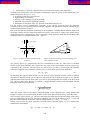
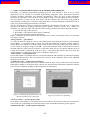
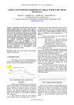
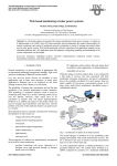
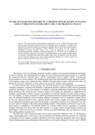
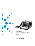
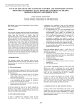
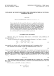
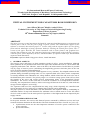
AUTHORS CONTENTS 15th International Research/Expert Conference ”Trends in the Development of Machinery and Associated Technology” TMT 2011, Prague, Czech Republic, 12-18 September 2011 VIRTUAL INSTRUMENT FOR CAPACITORS BANK DIMENSION Anca Miron, Mircea Chindris, Andrei Cziker Technical University of Cluj-Napoca, Electrical Engineering Faculty, Department of Power Systems, 28th Memorandumului Street, Cluj-Napoca, 400114 Romania ABSTRACT The paper presents a virtual instrument developed for capacitors bank dimension as to compensate the reactive power and to raise the power factor in power systems. The mathematical support of the software is accurately described in papers 2nd section, along with the negative effects of a low power factor and the advantages of using capacitors banks for reaching the neutral power factor. The 3rd section of the paper describes the virtual instrument with its main features and graphical user interface that contains 6 parts. The capacitors bank sizing is made based on the following criterions: reach the power factor imposed by the user, minimum number of capacitors bank steps, and minimum capacitors bank dimensions. Keywords: capacitors bank sizing, power factor, virtual instrument 1. GENERAL ASPECTS The reactive power and energy are basic quantities existing in all a.c. power installations. Although these quantities do not produce useful effects like light, heat, mechanical work etc., theirs nature and singularity make them vital. Likewise, most of the times, the achievement of useful effects is possible only by usage of reactive power (considering the magnetizing processes that take place in the iron cores of electric machines and transformers). The necessity of reactive power flow control appears at every consumer. The adopted solution for this problem during sinusoidal operating states is to use capacitors bank (CB). These electric components are usually installed at the substations low voltage busbars, which connect the end users to the rest of the distribution power network. The priority target is to reach an average power factor (PF) (at least the neutral) in the active and reactive powers measurement points of the downstream electric installations. The success of this action has as result the avoidance of overcompensation situations. Generally, the compensation is made to achieve an average PF between 0.93 and 0.97, with which the energy from the supplier is received [1]. The capacitors bank used for compensation has many steps, which frequently are controlled with special automatic devices; in this way a constant value of the PF can be maintained. The paper presents a virtual instrument (VI) that dimensions the capacitors bank by establishing its minimum number of steps and determines the minimum value at which must be set the PF control device in order to achieve on the entire period of operation a value higher than the one imposed by the supply contract. 2. CONSUMER POWER FACTOR In the power networks, the reactive and distorted powers consumed by different receivers and even networks elements determine the PF reduction. The main elements that cause a low PF are [1,2,3,4,5]: asynchronous motors are the most important consumers of reactive power connected to the power networks; power transformers; 537 AUTHORS CONTENTS electric lines, in general, consume reactive power because of their own inductance. A small power factor has a series of negative consequences upon the power system functioning. The main consequences are [1, 2, 3, 4, 5]: increasing of the active power losses; supplementary investments; growing of the voltage losses in the network; reduction of the power installations capacity; disturbance on the phone lines, TV, because of the distorted power etc. For the reactive power compensation, especially in the electric networks from the industrial companies, the use of capacitors bank represents a popular and appropriate solution considering the technical and economical aspects. Due to the fact that the natural PF, practically in all companies, is smaller than the neutral, imposed in the supply contract and for which no penalties are paid, it is necessary to improve the natural PF by using reactive power compensation. This is realized by using capacitors bank that are installed at the consumer busbars, in parallel with this one – figure 1. Q 2 = Q 1− QCB P s (A) P S1 U A =U1 c QBC Q1 φ1 CB S2 φ2 QBC Q1 ΔPc Q2 P = const. Figure 1. Capacitors bank installation at the consumer Figure 2. The phasory diagram in the installing point of the capacitors bank The reactive power QCB generated by the CB is transmitted in node (A). This power is assumed entirely by the local consumer, but it represents only a part of the total amount of reactive power Q1, requested by the consumer. The other part of reactive power Q2 that is uncovered by the capacitor bank CB is supplied to the consumer from the power system and it represents the difference: Q2 = Q1 − QCB . (1) By mounting the capacitor bank in node (A), the reactive power supplied from the system is reduced. The phasory diagram in node (A), to which is connected the CB, is showed in figure 2. It is put into light the phase angle decrease from value φ1 to value φ2 and consequently the raising of the PF in node (A). The new value of the PF that, in principle, is bigger than the neutral, can be calculated with the following mathematical expression: λ2 = P P + (Q1 − QBC ) 2 2 . (2) Since the neutral value, as the supply contract demands, at the substation low voltage busbars that supply a company can vary between 0.92 and 0.93, the CB is determined in order to reach this value. The necessary reactive power, QC, calculus of the capacitors bank imposes the knowledge of the active power P absorbed by the receiver, the natural (unimproved) value of the inductive PF λ1 = cosϕ1 and the value of the imposed (neutral) PF, after the improvement (λ2 = cosϕ2 > λ1 = cosϕ1). Taking into account the phase quantities from the power diagram (figure 1); it is obtained the mathematical relationship: QBC = P ⋅ tan φ1 − P ⋅ tan φ2 = Q1 − Q2 . 538 (3) AUTHORS CONTENTS 3. VIRTUAL INSTRUMENTS FOR CAPACITORS BANK DIMENSION LabVIEW is a graphical programming language that uses icons instead of lines of text to create applications [6]. In contrast to text-based programming languages, where instructions determine program execution, LabVIEW uses dataflow programming, where the flow of data determines execution. In LabVIEW, a user interface can be built by using a set of predefined tools and objects. The user interface is known as the front panel, and the customer may add codes using graphical representations of functions to control the front panel objects. The block diagram contains this code; in some ways, the block diagram resembles a flowchart. The VI developed in LabView graphical programming environment, derived from a load curve obtained with different recording apparatus (power quality analyzers, meters etc.), enables the dimension of a capacitors bank. The capacitors bank sizing is made based on the following criterions: reach the PF imposed by the user; the number of the capacitors bank steps is minimum; the capacitors bank has minimal dimensions. Figure 3 illustrates the frontal panel of the developed VI. It can be seen that the software is structured on 6 parts as follows: „Date generale” – general data It is the first block in which the user is asked information concerning the structure of the analyzed system: PCC – is the button used to choose the point that bounds the consumer and the suppliers, namely the point in which it is wanted to improve the PF above the neutral value. This point can be set to low voltage or medium voltage levels; BC – represents the button used to choose the level where the bank capacitor will be placed. No matter of the chose made, the user is asked to indicate the level voltage from which is acquired the load curve; CS – is the button that specifies the level where the measurements were made; this can be at low or medium voltage levels. „Date consum” – consumption data It is the block used to upload the load curves based on which the CB dimension is performed regarding the structure chosen before. The active and reactive powers can be visualized. These can be uploaded through a txt file, figure 4. „Parametrii Trafo” – transformer parameters In the case the acquired load curve level is different than the PCC; it has to take into account also the transformers influence. In this part of the software are introduced the transformers parameters and the power losses for different loadings of the transformer are determined. Figure 3. Choosing of the point where the capacitors bank will be connected Figure 4. Load curves uploading „Necesar reactiv” – reactive power needs In the frame of this block, it is determine the need of reactive power based on the active and reactive power load curves and taking in consideration the average PF that the beneficiary wants, figure 5. „Dimensionare BC” – bank capacitor dimension 539 AUTHORS CONTENTS It is the block in whose frame information concerning the necessary CB is obtained. In this block the PF after the compensation is shown that is close to the one imposed by the beneficiary in the previous block. „Raport” - report This software part presents a report about the needed capacitors bank, the power of the capacitor fixed step and the number of used steps. In the developed software two types of steps are taken in consideration: raw and fine. The number of steps is calculated and each step is properly sized. Also it is determined the varmetric regulator type (steps number). The most popular regulators have 6, 8, 10, 12 and 14 steps. In the frame of this report is also indicated the value that the regulator must set to in order to obtain the most appropriate value of the average PF imposed by the user, with the condition to get at least that value, figure 6. Figure 5. Reactive power needed in order to get an average PF of 0.92 Figure 6. Report concerning the capacitors bank sizing 4. CONCLUSIONS The reactive power and energy are basic quantities existing in all a.c. power installations. Although these quantities do not produce useful effects like light, heat, mechanical work etc., theirs nature and singularity make them vital. Likewise, most of the times, the achievement of useful effects is possible only by usage of reactive power (considering the magnetizing processes that take place in the iron cores of electric machines and transformers). The paper presents a VI that dimensions the capacitors bank necessary to compensate the PF in the bound point of the consumer. This instrument is useful for the consumers that want to raise the PF and consequently the power efficiency, but also to the power suppliers. For the last ones, this software brings the following advantages: Capacitors bank dimension is made based on the real load curves; It is considered the minimum value for the capacitors in order to obtain the imposed PF; It is determined the minimum value to which has to be set the control device in order to obtain a PF higher than the one imposed in the supply contact for the entire functioning period; There can be determined more scenarios for the PF compensation. 5. REFERENCES [1] Golovanov N., et. all. Power installations and industrial survey elements, TIPOGAL Publishing House, Galaţi, 2008. [2] Golovanov N., Postolache P. and Toader C., Power quality and energy efficiency, AGIR Publishing House, Bucureşti, 2007. [3] Golovanov Carmen, et all. Modern measurement problems in power systems, Tehnică Publishing House, Bucureşti 2002. [4] Cziker, A., Miron, Anca, Chindris, M., A new power factor compensation strategy for highly unbalanced low voltage electrical networks. CIE 2010, Băile Felix, 27-29 Mai 2010, Oradea. [5] Angelo Baggini (editor), et all. Handbook of Power Quality, John Wiley&Sons, Ltd, 2008. [6] ***. LabVIEW User Manual, National Instruments, April 2003 Edition, Part Number 320999E-01. 540