1
User Guide
EurothermSuite, T800, T940, T3500
ELIN COMMS
E U ROT H E R M
© 2005 Eurotherm Limited
All rights are strictly reserved. No part of this document may be reproduced, modified, or transmitted in
any form by any means, nor may it be stored in a retrieval system other than for the purpose to act as an
aid in operating the equipment to which the document relates, without the prior written permission of
Eurotherm limited.
Eurotherm Limited pursues a policy of continuous development and product improvement. The specifications in this document may therefore be changed without notice. The information in this document is
given in good faith, but is intended for guidance only. Eurotherm Limited will accept no responsibility
for any losses arising from errors in this document.
ELIN USER GUIDE
ELIN User guide
List of Contents
Section
Page
1. OVERVIEW ................................................................
1.1 COMPATIBILITY ..................................................................
2 CABLING ...................................................................
3. LIN NODE NUMBERS .................................................
3.1 LIN NODE NUMBER MAPPING ...........................................
3
3
3
4
4
3.1.1 Allocation of Own IP Address and Port Number ........................ 4
ISOLATED ELIN NETWORK .................................................... 4
ISOLATED ELIN NETWORK WITH
DEFINED ADDRESSING SCHEME ........... 5
NON-ISOLATED ELIN NETWORK ........................................... 5
3.1.2 Mapping LIN node numbers to IP address and Port number ........ 6
4 PROTOCOL NAMES ....................................................
5 CROSS-SUBNET WORKING .........................................
5.1 FIREWALL CONFIGURATION ..............................................
6. DIAGNOSTIC BLOCK TYPES ........................................
6.1 ELINDIAG BLOCK TYPE ......................................................
6.2 EMAPDIAG BLOCK TYPE ....................................................
6.3 PRPDIAG BLOCK TYPE ........................................................
6.4 ELIN ADVANCED CONFIGURATION ...................................
APPENDIX A: INSTRUMENT-SPECIFIC INFORMATION .......
A1 PROCESS SUPERVISOR .......................................................
A1.1 ELIN CONNECTORS ........................................................
A1.2 TERMINAL CONFIGURATOR WITH ELIN ............................
A1.3 ELIN SETUP PAGE .............................................................
A1.4 ALIN / ELIN LEDS ............................................................
A2 VISUAL SUPERVISOR ...........................................................
A2.1 COMPATIBILITY ................................................................
A2.2 ELIN CONNECTORS ........................................................
A2.3 COMMS CONFIGURATION .............................................
APPENDIX B: PC CONFIGURATION ................................
B1 LOCAL IP SETUP ..................................................................
B2 ELIN SETUP .........................................................................
B3 MULTI HOMED HOSTS ........................................................
B4 REMOTE SUBNET NODE LIST ...............................................
B5 THE NETWORK INTERFACE .................................................
B6 LINDEVICE_N SECTION ......................................................
B7 THE NETWORK.UNH FILE ....................................................
B8 EUROPRP.EXE......................................................................
7
8
8
9
9
11
12
13
14
14
14
15
16
17
18
18
18
19
21
21
22
22
22
23
23
23
24
Cont...
HA082429
Issue 3 Feb 05
Page 1
ELIN USER GUIDE
List of Contents (Continued)
Section
Page
APPENDIX C: IP ADDRESSING ........................................
C1 IP ADDRESSING .................................................................
C1.1 IP SUBNETS ....................................................................
C1.2 IP SUBNETS / CROSS SUBNET WORKING ........................
C1.3 CLASS-BASED ADDRESSING ............................................
APPENDIX D: IP ADDRESS ALLOCATION METHODS ..........
D1 MANUAL IP ADDRESS CONFIGURATION .............................
D2 DHCP ................................................................................
D3 LINK-LOCAL .......................................................................
APPENDIX E: NETWORK.UNH FILE ..................................
APPENDIX F: GLOSSARY ...............................................
INDEX ...........................................................................
Page 2
25
25
25
25
25
26
26
26
26
27
28
29
HA082429
Issue 3 Feb 05
ELIN USER GUIDE
ELIN USER GUIDE
1. OVERVIEW
This document describes the differences between using ELIN and ALIN. For many users this will be limited to slight
differences concerning cabling and connectors. For more ambitious users wishing to operate ELIN over wide area
networks, some knowledge of IP networks is required, as is some additional configuration.
Note: The term ‘Process Supervisor’ is used to describe models T940 and T940X. The term Visual Supervisor
is used to describe the Model T800.
1.1 COMPATIBILITY
ELIN is supported by Process Supervisor version V3.1 or higher, Visual Supervisor version V5.0 or higher, and by
EurothermSuite Versions V1.7.3 onwards. Patches are available for previous versions of EurothermSuite.
Appendix A gives information on how to configure Process Supervisors and Visual Supervisors.
Appendix B gives information on how to configure a PC.
2 CABLING
ELIN cabling to Eurotherm instruments uses standard Ethernet Category 5 (“CAT5”) cable fitted with RJ45 plug connectors. Such cables are now considered to be the standard computer network cable and hence are readily available, in
various lengths, from a large number of suppliers.
Each ELIN instrument is provided with an RJ45 socket for ELIN connection. The User Guide, or Handbook supplied
with the instrument (either as a printed manual or as a pdf file on CD) gives wiring details.
Host PCs need to be fitted with a standard Ethernet card providing an RJ45 Ethernet connector.
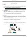
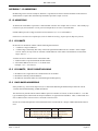
Network cabling for ELIN uses “star” topology (figure 2). I.E. Each ELIN-connected LIN Node has a separate cable
back to a hub. Terminators are not required for ELIN.
Instrument 1
Instrument 2
Instrument 3
PC
Ethernet Hub
PC
Instrument 5
Instrument 4
Figure 2 Star topology example.
HA082429
Issue 3 Feb 05
Page 3
ELIN USER GUIDE
3. LIN NODE NUMBERS
A LIN Node is uniquely identified by its 8-bit LIN Node Number (usually expressed as a 2-digit hexadecimal
number). On most instruments, Node Number is set via ‘DIP’ switches. On the Visual supervisor the addresses are set
from the operator interface (as described in section A2.3). Refer to the User Guide or Handbook supplied with the
instrument for full details.
3.1 LIN NODE NUMBER MAPPING
ELIN continues to use the same method of LIN Node Numbers to identify LIN Nodes. However ELIN runs over Ethernet using IP (Internet Protocol). IP hosts are identified by an “IP address”. The LIN protocol is a service accessed
through a single port at a given IP address. See Appendix C for a description of IP addressing.
On instruments there is a one-to-one mapping of LIN Node Number to “IP address plus Port Number”. A single PC
may support multiple LIN Node Numbers at the same IP address, with each LIN Node Number assigned to a different
Port Number at the same IP address. In either case a single “LIN Node Number” always maps to a single unique combination of “IP address + Port No”.
In order to support ELIN, each ELIN Node has two additional functions over and above previous versions of LIN:
1. Allocation of its own IP address and Port No;
2. The mapping of other LIN Node Numbers to IP address and Port No.
3.1.1 Allocation of Own IP Address and Port Number
ELIN always allocates Port Numbers automatically. By default, all instruments use Port Number 49152, whereas PCs
allocate the “next available” Port Number. In either case, no user interaction is required to allocate the Port Number.
An IP host (PC or instrument) will need to be allocated an IP address – this can be allocated either automatically or
manually. The chosen method and the values of IP address allocated, depends on any existing (or planned) network
topology at the site. In its simplest form, no user configuration is required. See Appendix D for a discussion of IP
address allocation methods (manual, DHCP and Link-Local).
ISOLATED ELIN NETWORK
This is the simplest form of ELIN network. It consists of a number of LIN Nodes (IP hosts) which are connected together via a local area network, with which no other IP networks are to inter-operate, and over which only ELIN traffic is to be passed.
In such a system, the minimum amount of configuration is required. The PCs are set to “Obtain an IP address automatically” (this is the default). ELIN instruments have the same default.
Caution
If the IP configuration is part of a company network, do NOT CHANGE the configuration without consulting
the relevant IT manager.
PCs and some instruments initially attempt to obtain their IP address settings via DHCP or BootP. When this fails
(there being no DHCP server present) they default to using Link-Local to obtain their IP addresses. Link-Local involves a level of negotiation between the various IP hosts to ensure they all end up with unique IP addresses. IP addresses assigned by Link-Local are always in the range 169.254.X.Y.
Page 4
HA082429
Issue 3 Feb 05
ELIN USER GUIDE
LIN NODE NUMBER MAPPING (Cont.)
ISOLATED ELIN NETWORK WITH DEFINED ADDRESSING SCHEME
Similar to ‘Isolated ELIN Network’ described above, but local IT policy requires the use of defined IP addressing
schemes. It is beyond the scope of this document to discuss the reasons behind such IP addressing schemes, other than
to say that the local IT department should be consulted on questions concerning the local IT policy.
Addressing schemes may be imposed either by use of a DHCP server, or by explicit settings at each IP host.
The use of a DHCP server is more common, as everything can be configured at a central point. Under these circumstances, configuration of PC and instruments is the same as that described above. I.E. default settings are used.
IP address and Subnet Mask can be set explicitly at each PC and instrument. See Appendix A for specific information
for instruments. See Appendix B for specific information for PCs.
NON-ISOLATED ELIN NETWORK
A non-isolated network is a network subnet which has links to other network subnets (either within the same site/
organisation, or possibly to wide area networks which may include the public internet). Such a system must have a
defined addressing scheme.
Managing a network infrastructure of this scale is not a simple job, and it is assumed that if this requirement exists, a
local IT department will also exist, to manage the system.
Such addressing schemes may be imposed either by use of a DHCP server, or by explicit settings at each IP host.
IP address and Subnet Mask can be set explicitly at each PC and instrument. See Appendix A for specific information
for instruments. See Appendix B for specific information for PCs.
HA082429
Issue 3 Feb 05
Page 5
ELIN USER GUIDE
3.1.2 Mapping LIN node numbers to IP address and Port number
All ELIN Nodes operate a Port Resolution Protocol (PRP) which handles the problem of resolving the mapping of a
remote LIN Node Number to the appropriate IP address and Port Number. Operation of PRP is (for the most part)
invisible. The user specifies the LIN Node Number of the remote LIN node, and PRP automatically derives the real IP
address and Port Number.
The only circumstances under which PRP is not fully automatic is where a LIN Network is being constructed from a
collection of LIN Nodes which are located on more than one subnet.
PRP cannot automatically locate LIN Nodes on “other subnets” because “other subnets” could literally include the
entire world. However, once one LIN Node has learnt about one other LIN Node on another subnet, it shares that
information with all other LIN Nodes on the local subnet. The effect of this is that all LIN Nodes on all subnets
‘learn’ about all other LIN Nodes on the complete LIN Network. This requires minimal configuration.
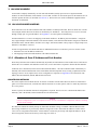
The rule for configuration of “cross subnet” working is as follows: “At least one LIN Node on each subnet must be
configured with the IP address of at least one LIN Node on each of the other subnets which make up the entire LIN
Network”. See figure 3.1.2 and subsequent text, for an example
Instrument
A
Subnet 1
Subnet 2
Instrument
B
Instrument
C
Figure 3.1.2 Cross subnet example
In this example there is a single instrument (“A”) on subnet 1, and two instruments (“B” and “C”) on subnet 2.
If A is configured with the IP address of B, then B learns about A when A tries to talk to B. Once B has learnt about A
it shares this information with C.
C then tries to talk to A, which then learns about C.
All LIN Nodes now know about all other LIN Nodes on the LIN Network, even though only LIN Node A had any
specific “cross subnet configuration”.
Page 6
HA082429
Issue 3 Feb 05
ELIN USER GUIDE
4 PROTOCOL NAMES
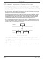
LIN supports a maximum of 254 valid Node Numbers (Hex 01 to Hex FE). Large systems may need to exceed this by
using multiple logical LIN networks coexisting on the same physical network. This can be achieved by using Named
LIN Networks (see figure 4 for a simple example).
By default, all instruments form part of the “NET” network, but this default name can be overridden in the
network.unh file. This ‘named LIN network’ must be included in the [LIN] section of the “network.unh” file. See
Appendix E for details of the network.unh file. See Appendix A for instrument-specific information, and Appendix B
for PC-specific information.
PC (ELIN)
(>90)
Addresses in hex.
PC (ELIN)
(>90)
ELIN
Instrument A
(>3F)
Instrument B
(>44)
Protocol = LIN_A
Instrument A
(>3F)
Instrument
B (>44)
Protocol = LIN_B
Figure 4 Named LIN networks example
HA082429
Issue 3 Feb 05
Page 7
ELIN USER GUIDE
5 CROSS-SUBNET WORKING
By default, all ELIN LIN Nodes disable the ability to communicate cross-subnet. This is a security feature designed to
prevent unauthorised access over wide area networks. In order to enable cross-subnet working it is necessary to enable the “AllSubnet” feature through the network.unh file. It is also possible for the Process Supervisor to enable and
disable cross-subnet working dynamically, at runtime. See Appendix A for configuration details . See Appendix B for
PC configuration.
When cross-subnet working is enabled, the necessary security features should be put in place to prevent unauthorised
access. It is the responsibility of the company installing the instrument to ensure that a Firewall or other protective
device is in place to prevent unauthorized access.
5.1 FIREWALL CONFIGURATION
The following information is provided to assist IT personnel with firewall configuration:
1. PRP uses UDP port 1264
2. ELIN uses UDP.
3. ELIN instruments always use port 49152.
4. ELIN on PCs uses dynamically allocated ports.
5. ELIN systems require both PRP and ELIN to pass through firewalls in order to function correctly.
6. ELIN and PRP can cope with NAT, but they expect a consistent configuration. For example, if an IP address from
another subnet is NATed to appear as if it is on a local subnet, ELIN and PRP expect broadcasts to reach that IP
address (this requires the NAT router to generate pseudo-broadcasts to ensure the packets reach the destination).
7. ELIN expects all LIN nodes on a logical LIN network to be reachable from all other nodes. For example, if there
are two LIN nodes inside a firewall, and two LIN nodes outside a firewall, all forming part of the same logical
LIN network, then it is essential that both LIN nodes outside the firewall are allowed to communicate with both
LIN nodes inside the firewall (and vice versa). Allowing only partial connectivity causes significant problems,
particularly for the LIN Network Explorer utility.
Common practice is to allow hosts inside the firewall to initiate access to the outside; but not vice versa. If such a
policy is adopted then it is necessary to configure at least one of the ELIN nodes inside the firewall with the IP
addresses of all ELIN nodes outside the firewall. This must be done to ensure the correct operation of remote
cross-subnet learning of mapping (see section 3.1.2).
Page 8
HA082429
Issue 3 Feb 05
ELIN USER GUIDE
6. DIAGNOSTIC BLOCK TYPES
In order to assist in the debugging and fault finding of ELIN systems, diagnostic blocks have been added to the LIN
Database.
6.1 ELINDIAG BLOCK TYPE
OVERVIEW
Block: elind_54
Type: ELINDIAG
Compound:
------------------------------------------------------------------------|
LLCport
0
| Alarms
MACport
0
|
MACtype
ELIN
| txCount
627
MACstate Online
| txTimeOut 0
Procesor Primary
| txReject
0
lastErr
0
| txImmRsp
314
| noImmRsp
0
ThisNode >0554
|
ThisIP
149.121.165.188
| rxCount
627
ThisPort 49152
| rxReq
314
| rxRspOk
275
RemEntry 0
| rxUnknwn
0
RemNode
>0112
| rxRspErr
0
PrimIP
149.121.165.45
| rxRspBsy
39
PrimPort 1065
|
ScndIP
0.0.0.0
| ClearCnt
FALSE
ScndPort 0
|
ScWeight 32767
| PrevNode
>0112
NAT
FALSE
| NextNode
>0112
Remstate Known
|
|
LLCport and MACport
MACtype
Normally both zero, as most LIN Nodes support only a single LIN interface.
Should be ELIN. If an attempt is made to operate this block with a different LIN type (e.g.
ALIN) then the correct LIN type will be displayed here – but the remainder of this block will
not function.
MACstate
Should always show “OnLine” any other value indicates a serious internal error.
Procesor
Should always read “Primary”. ELIN is redundant processor aware – but it is not possible to
view blocks running on a secondary processor.
LastErr
Should always read “0”. If MACstate is not “OnLine” it may show an error code which can
help identify the reason.
ThisNode, ThisIP, ThisPort These fields show the LIN Node Number to IP address + Port Number mapping for this LIN
Node.
RemEntry
This field shows the index number into a table of remote LIN Node Number mappings. As
entries are added and removed from the table, so individual entries can change their index.
Setting this field to “-1” allows you to enter the required remote node number into the
RemNode field (although the ScWeight field does not work in this mode). NOTE: ELIN only
maintains mappings of nodes it actually wishes to talk to - do not expect to find a mapping
entry for a node if there is no LIN traffic between that node and this node.
PrimIP, PrimPort
These show the IP address and Port Number mapping for the Primary processor at the LIN
Node Number shown in RemNode.
ScndIP, ScndPort
The IP address and Port Number mapping for the Secondary processor at the LIN Node
Number shown in RemNode. If this LIN Node Number is not a redundant pair, then these
fields are “0”.
(Continued)
HA082429
Issue 3 Feb 05
Page 9
ELIN USER GUIDE
6.1 ELINDIAG BLOCK TYPE (Cont.)
ScWeight
NAT
Remstate
TxCount
TxTimOut, txReject
TxImmRsp
NoImmRsp
RxCount
RxReq
RxRspOk
RxUnknown
RxRspErr
RxRspBsy
ClearCnt
PrevNode, NextNode
Page 10
Shows the “weight” of the Secondary processor at the LIN Node Number shown in RemNode.
A “weight” of 2 indicates a physical secondary processor. A “weight” of 1 indicates a secondary network interface on the primary processor. A “weight” of 3 indicates a secondary network
interface on the secondary processor.
If TRUE this indicates that the given IP address and Port Number mapping has been subject to
NAT (“Network Address Translation”). This means that the real IP address and Port Number of
the remote node are different to that displayed, but that these values have been “translated” enroute by a NAT-router.
This indicates the quality of the mapping. The values “unresolved” and “known” have obvious
meanings. If you see the value “assumed” – this means that traffic has been received from the
specified node using the specified IP address and Port Number, but that the mapping has not
been confirmed by PRP. LIN communications can successfully take place using an assumed
mapping – but this is normally only a transitory state.
A count of attempted packet transmissions
Unused
A count of “immediate responses” sent to acknowledge received packets.
A count of attempted packet transmissions for which no immediate response was received.
A count of received packets
A count of received packets which were valid request packets
A count of received request packets to which an “OK” response was sent
Unused
A count of received packets which cannot be correctly identified
A count of received request packets to which a “busy” response was sent.
This field should be set TRUE, in order to zero all the “count” fields.
Gives the LIN Node Number of the numerically next lower and higher LIN Nodes Numbers
on this network. (Note these values “wrap round” through Hex 00 and Hex FF).
HA082429
Issue 3 Feb 05
ELIN USER GUIDE
6.2 EMAPDIAG BLOCK TYPE
OVERVIEW
Block: emapd_54
Type: EMAPDIAG
Compound:
------------------------------------------------------------------------|
Seg0_map >0000
| Alarms
Seg1_map >0004
|
Seg2_map >0000
| NodeStat >12
Seg3_map >0000
|
Seg4_map >0000
| NodePrev >54
Seg5_map >0010
| NodeNext >54
Seg6_map >0000
|
Seg7_map >0000
| TimeNow
>D78D
Seg8_map >0000
| LastI_Am >D788
Seg9_map >0000
|
SegA_map >0000
|
SegB_map >0000
|
SegC_map >0000
|
SegD_map >0000
|
SegE_map >0000
|
SegF_map >0000
|
|
ThisNode >54
|
PrevNode >12
|
NextNode >12
|
|
This block shows a complete map of all LIN Nodes on this LIN Network – regardless of whether this node specifically communicates with the other nodes. The particular LIN Network in this example has only two LIN nodes on it.
In the following descriptions, the’>’ character indicates that the value is in hexadecimal notation.
Seg0_map to SegF_map
ThisNode
PrevNode, NextNode
NodeStat
NodePrev, NodeNext
TimeNow
LastI_Am
HA082429
Issue 3 Feb 05
Each of these is a 16-bit bitfield, where each bit represents a single LIN Node (between 0 and
F) in segment ‘N’ of the network, where N is also between 0 and F.
Thus, for SegN_map, a value of >0001 would imply node >N0 only; >0002 would imply
Node >N1 only; >0003 = Nodes >N0 and >N1, and so on. As an example, for Seg3_map, the
node numbers would be >30, >31 and >30 + >31, and so on.
Hence the value “>0004” in the field Seg1_map corresponds to LIN Node Number >12; and
the value “>0010” in the field Seg5_map corresponds to LIN Node Number >54.
This shows the LIN Node Number of the instrument on which the block is running.
Gives the next lower and higher LIN Node numbers on this network. (Note these values ‘wrap
round’ through Hex 00 and Hex FF).
In this field you can enter the Node Number of another LIN node on the network in order to
monitor its presence on the network.
Gives the next lower and higher LIN Node numbers on this network, relative to the node
number in NodeStat. (Note these values ‘wrap round’ through Hex 00 and Hex FF).
Gives the current system time
Gives the system time at which the existence of the LIN Node Number (specified in NodeStat)
was last confirmed.
Page 11
ELIN USER GUIDE
6.3 PRPDIAG BLOCK TYPE
OVERVIEW
Block: prp_54
Type: EMAPDIAG
Compound:
------------------------------------------------------------------------|
SIndex
0
| Alarms
Status
Identified
|
Serial
89
| TxTS
>000C50F8
NetNo
0
| String1T Try|149.
SecsToGo 22
| String2T 121.173.
Prot_S
LIN.RKN
| String3T 1 |
Node
0x0554
| String4T E
Comment
T940 V3.
|
IP
149.121.165.188
| RxTS
>000C6C02
Port
49152
| String1R Try|149.
Weight
0
| String2R 121.173.
| String3R 1 |
CIndex
0
| String4R 40 V3.1C
Prot_C
|
Inst1
| TimeNow
>000C78D3
Inst2
|
|
|
|
|
|
The primary purpose of this block is to expose the inner workings of the PRP. The details of PRP are beyond the
scope of this document. One field, however, may be of interest:
Prot_S
Page 12
This string which identifies the “Protocol Name”. It always starts with the 4 characters “LIN.” The remaining characters show the configured protocol name (“NET” by default). Remember that only LIN Nodes with
same Protocol Name are considered to be part of the same LIN Network.
HA082429
Issue 3 Feb 05
ELIN USER GUIDE
6.4 ELIN ADVANCED CONFIGURATION
Products that support bridging between ALIN & ELIN, now support configuration of the timeouts and retries associated with ELIN.
ELIN is based on IP and was originally designed to run over high speed Ethernet. However IP can just as easily be run
over slower links, in which cases, standard ELIN may start to encounter errors due to the short timeouts etc. On a
T225 these timeouts are configured on the ELIN page. In NTSE they are configured in NTSE.INI in the LINOPC
install directory.
Problems normally manifest themselves as communications alarms, because repeated errors force a disconnection
between the end nodes. If this is the case then increasing the timeouts or retries may solve the problem.
Timeouts/retries
Interpretation
Unack Timeout
Rmt Unack Timeout
No of retries
Fwd No of retries
UnThrottled Tx Lim
Busy Throttle Time
EDB Connect Used
EDB Connect Unused
EDB Timeout Used
Low level Timeout if no response on a local IP Subnet
Low level Timeout if no response on a remote IP Subnet
Number of low level retries
If acting as a bridge forwarding message, the number of low level retries
Number of consecutive busies before applying a delay between transmits
Delay between tranmits after “UnThrottled Tx Lim” consecutive busy’s
Timeout on a connection via a T225/NTSE if there is data being sent.
Timeout on a connection via a T225/NTSE if there is no data being sent.
Timeout on an external database connection via ELIN if there is data
being sent.
Timeout on an external database connection via ELIN if there is no data
being sent.
EDB Timeout Unused
HA082429
Issue 3 Feb 05
Default
100ms
250ms
3
100
10 (100 NTSE)
50 (0 NTSE)
5Secs
30Secs
5 secs
30 secs
Page 13
ELIN USER GUIDE
APPENDIX A: INSTRUMENT-SPECIFIC INFORMATION
A1 PROCESS SUPERVISOR
All Process Supervisors prior to V3/1 were ALIN instruments. The hardware included an Arcnet card fitted internally
to the unit to provide ALIN support.
Process Supervisor software V3/1 and later checks for the presence of an internal Arcnet card, and if one is fitted it
defaults to ALIN operation. If no internal Arcnet card is fitted, the unit defaults to ELIN operation.
It is possible to override this default behaviour when an arcnet card is fitted by setting the “ELIN=on” option in the
network.unh file (see Appendix E).
A1.1 ELIN CONNECTORS
As shown below, ELIN uses the System A connectors for each processor.
Note: Unlike other communications connectors, the ‘System’ connector pairs are not wired in parallel with
one another.
Process Supervisor
Connect
ELIN
(Left)
ELIN
(Right)
system
A
B
A
B
in
out
in
out
in
out
in
out
i/oA
in
out
i/oB
in
out
exp1
in
out
in
out
exp2
rl1
rl2
+
-
alarms
wdog batt
+
-
A
B
left processor
rl1
+
24V
rl2
wdog batt
+
-
A
B
right processor
Figure A1 ELIN connector locations
Page 14
HA082429
Issue 3 Feb 05
ELIN USER GUIDE
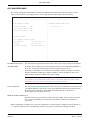
A1.2 TERMINAL CONFIGURATOR WITH ELIN
The terminal configurator provides a sign-on screen which provides some important information concerning the
ELIN/IP/Ethernet configuration. A typical sign-on screen might look like this:
EPA T940 Process Supervisor - V3/1 Beta version - 31H at 133 MHz
(Hardware Build: 00 - 1Mbyte SRAM fitted at Hex D00000)
Profibus card: PB-COMBIC104-PB Version: V01.058 29.05.01
Ethernet (MAC) address = 00:E0:4B:00:45:DA
IP address = 149.121.165.188
Subnet mask = 255.255.252.0
Default gateway = 149.121.164.253
POST result (0000) = SUCCESS
Hotstart failed because: Warmstart switch is disabled
Last shutdown because: Successful Power Down
1 ANSI-CRT
>>>
The following items refer to the ELIN/IP/Ethernet interface:
Ethernet (MAC) address
IP address
This shows the address of the Ethernet interface. This value is unique and is permanently fixed
for an individual instrument.
The IP address currently assigned to this instrument. It may be configured within the instrument or derived by BootP or Link-Local.
Note: The IP address must be entered manually for Process Supervisors.
Subnet Mask
Default Gateway
HA082429
Issue 3 Feb 05
Gives the subnet mask currently assigned to this instrument. An IP host uses the subnet mask,
in conjunction with its own IP address, to determine if a remote IP address is on the same
subnet (in which case it can talk directly to it), or a different subnet (in which case it must talk
to it via the Default Gateway). See Appendix C for further details.
The IP address of the Default Gateway. It is the address via which this instrument must talk in
order to communicate with IP addresses on other subnets. If undefined (0.0.0.0) then this
instrument can talk to other IP hosts only if they are on the same subnet.
Page 15
ELIN USER GUIDE
A1.3 ELIN SETUP PAGE
The terminal configurator Utilities Menu now offers the additional ELIN Setup Page. This page allows an instrument’s network.unh file to be configured from a user-friendly interface, rather than by direct file editing.
ELIN Setup (network.unh file)
------------------------------------------------------------------------|
LIN PROTOCOL SETUP
| REMOTE SUBNET NODE LIST
|
Protocol Name
RKN
|
149.121.173.1
All Subnet Enable ON
|
Elin Only Enable
ON
|
|
|
LOCAL IP SETUP
|
|
Get Address Method Fixed
|
IP Address
149.121.165.45
|
Subnet
255.255.252.0
|
Default Gateway
149.121.128.138
|
|
|
|
|
|
|
|
|
LIN PROTOCOL SETUP
This section allows specification of those items in the “[LIN]” section of the network.unh file.
All Subnet Enable
By default, Process Supervisors will not communicate ELIN cross-subnet unless AllSubnet is
set to ‘On’. This defines the behaviour when the instrument first powers on.
The ability to communicate cross-subnet can be modified at runtime by using a new options
bit in the instrument’s header block “Options. AllSubnt”. Set this bit TRUE to allow crosssubnet working; FALSE to prohibit cross-subnet working.
Caution
It is possible to set this bit FALSE remotely from a cross-subnet connection. If this is done
communications are lost and it is not possible to reset the bit to TRUE
LOCAL IP SETUP
This section allows specification of those items in the “[IP]” section of the network.unh file. If
‘Get Address Method’ is specified as ‘Fixed’, then additional fields will be presented to allow
the specification of IP address, Subnet Mask and Default Gateway, as shown above.
Process Supervisor units must use ‘Fixed’.
REMOTE SUBNET NODE LIST
This section allows the specification of those items in the “[PR]” section of the network.unh
file. A list of the IP addresses of remote nodes with which it is desired to communicate is
entered here.
When configuration is complete, ESC is pressed. Confirmation is required in order to update the network.unh file. If
‘Y’ is typed (to update the file), the instrument will have to be power-cycled before the changes take effect.
Page 16
HA082429
Issue 3 Feb 05
ELIN USER GUIDE
A1.4 ALIN / ELIN LEDS
The health of the LIN interface is indicated by LEDs on the instrument’s front panel. ALIN health is indicated by the
I/O A LED; ELIN health is indicated by the System A LED.
It is thus possible to determine whether the unit is running ELIN or ALIN by observing which of the above two LEDs
is illuminated .
The LEDs indicate LIN status as follows:
Green – LIN is operating correctly
Red flash – external problem (e.g. cable break)
Red steady – internal problem (e.g. Process supervisor hardware fault).
Process Supervisor
Processor
Power
A
Alarms
B
24V
rl1
int ext
battery
rl2
Comms
exp1
system
ELIN LED
A
B
tx
rx
i/o
ALIN LED
exp2
primary
standby
sync
changeover
desync
Restart
wdog
halt
duplex
hot
hot/cold
cold
test
config
Figure A1.4 Processor module Comms LEDs
HA082429
Issue 3 Feb 05
Page 17
ELIN USER GUIDE
A2 VISUAL SUPERVISOR
A2.1 COMPATIBILITY
ELIN support is offered in Visual Supervisors with software levels of V5.0 upwards. Earlier versions can not be upgraded to support ELIN
A2.2 ELIN CONNECTORS
User termination is by means of an RJ45 connector located as shown (not to the same scale) in figures A2.2a and
A2.2b, below.
ALIN (ARCNET)
E
8
1
8
1
1
6
OR
1
5
9
L
N
8
8
13
25
ELIN (Ethernet)
1
14
1
8
5
1
6
9
8
NC NO C NCNO C
Health
Run
1
1
8
1
Slave Master
Figure A2.2a ELIN/ALIN connector location (small frame unit)
E
L
N
1
8
14
ALIN (Arcnet)
1
5
6
8
1
8
1
8
1
1
5
1 2 3 4
9
9
6
Fixed socket
1
OR
1
8
8
1
8
1
8
1
8
1
ELIN (Ethernet)
1
6
Figure A2.2b ELIN/ALIN connector location (large frame unit)
Page 18
HA082429
Issue 3 Feb 05
ELIN USER GUIDE
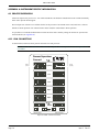
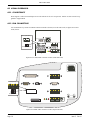
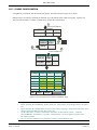
A2.3 COMMS CONFIGURATION
Configuration is carried out from the Comms Set-up page, accessed as shown in figure A2.3a, below.
Ethernet setup is accessed by operating the ‘Ethernet’ key at the bottom of the comms set-up page. Figure A2.3b
shows the relevant fields. To return to Comms setup, operate the Comms button.
2
Press SYSTEM key
ACCESS
SYSTEM
ALARMS
PROGRAMMER LOGGING
HOME
System
SUMMARY
1
APPLN
Press menu key
SETUP
3
CLONING
4
Press SETUP
Press COMMS key
Setup
STARTUP COMMS CLOCK
INTERNAT PANEL
Comms Setup
10:49:42
12/07/04
PORT
CFG
SLV
MST
Hardware
RS232
RS422
RS422
Protocol
SLIN
Modbus/S
Modbus/M
Node No.
1
0
Baud
9600
19200
19200
Parity
EVEN
EVEN
EVEN
Data Bits
8
8
8
SAVE
CANCEL
ETHERNET
Figure A2.3a Visual Supervisor Comms Configuration Page
Notes:
1. Before operating the ‘ETHERNET’ button, operate the ‘SAVE’ button, or all changes made so far will be
lost.
2. Before operating the COMMS button to return to the Comms setup page, operate the SAVE button, or all
changes made in the Ethernet setup page will be lost.
3. On the small frame (1/4 VGA) version of the instrument, the three buttons ‘SAVE’, ‘CANCEL’
and ‘ETHERNET’ are hidden by a scroll bar. The Option key is used to toggle between the scroll
bar and these buttons.
4. The user must have suitable access permission in order to edit the Ethernet setup.
HA082429
Issue 3 Feb 05
Page 19
ELIN USER GUIDE
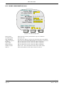
A2.3 COMMS CONFIGURATION (Cont.)
LIN Protocol setup
Protocol Name:
All subnet Enable:
Local IP Setup
MAC Address:
Address Assignment:
IP Address:
Subnet Mask:
Default Gateway:
MYENET
YES
EO:00:05:4B:D1:0B
Fixed
149.121.165.183
255.255.252.0
149.121.164.253
Remote Subnet Node List
Number of Nodes:
1
Node 1: 0 . 0 . 0 . 0
SAVE
CANCEL
COMMS
Figure A2.3b Ethernet setup items
Protocol name
All Subnet enable
MAC ADDRESS
Address Assignment
IP Address
Subnet Mask
Default Gateway
Number of nodes
Node N:
Page 20
Allows the user to enter a protocol name of up to 12 characters.
Select Yes or no.
This factory-set address is unique to the instrument and is non-editable.
Select one of: Fixed, DHCP, BootP, DHCP+LL, BootP+LL, Link Local.
May be edited only if ‘Fixed’ selected as Address assignment.
May be edited only if ‘Fixed’ selected as Address assignment.
May be edited only if ‘Fixed’ selected as Address assignment.
Enter 0 to 50. This is the number of nodes in the remote subnet.
Allows the IP address of each remote node to be entered..
HA082429
Issue 3 Feb 05
ELIN USER GUIDE
APPENDIX B: PC CONFIGURATION
B1 LOCAL IP SETUP
Caution
Many PCs already have IP addresses allocated because they are part of a company network. Changing the IP
set-up in such a case will almost certainly stop the PC from communicating with other PCs and servers on the
network.
The Process supervisors need to be allocated IP addresses that are compatible with any existing IP network. If in
doubt the IT manager or System Administrator should be consulted.
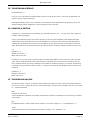
Figure B1 illustrates the properties dialogue for configuring the PC IP settings.
Figure B1 TCP/IP Properties page
Clicking on the ‘Obtain an IP address automatically’ means that the PC will use DHCP, with a Link-Local fallback
(Windows 98 and later). Selection of ‘Use the following address’ causes the greyed IP fields to become active, allowing the user to enter an IP address, subnet mask and default gateway, manually.
HA082429
Issue 3 Feb 05
Page 21
ELIN USER GUIDE
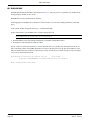
B2 ELIN SETUP
To configure as ELIN LINOPC port the LINOPC control panel applet (figure B2) is used. The dialogue box is similar
to the ALIN equivalent, but has an extra field: Protocol Name, which defaults to ‘NET’. The ELIN form does not
have any card information because it uses the standard Ethernet card.
Note: The Cold Start Database is not supported by ELIN
Figure B2 LINOPC page
B3 MULTI HOMED HOSTS
Multiple IP interfaces are supported by EurothermSuite versions 3.4 onwards. The way in which IP interfaces are
identified by the host computer varies according to which Windows operating system (NT, 2000, XP) is running on it.
Some machines have two or more different IP network types attached to them, for example, Dialup, Ethernet copper,
Wireless etc. Such machines are known as ‘multihomed hosts’.
There are two ways of specifying the interface: ‘Network interface = n’ and a section LinDevice_n, described in B5
and B6, below.
Notes:
1. For single homed hosts, it is recommended that Network Interface be set to 0 (NetworkInterface = 0),
and any {LINDevice_n] be omitted.
2. For mulitihomed hosts, the use of one or more [LINDevice_n] sections is recommended. This overrides
any NetworkInterface variable setting.
B4 REMOTE SUBNET NODE LIST
If ELIN nodes on remote subnets are to be accessed, then the network.unh file must be edited at the PC, using a text
editor such as Notepad. The file is to be found under …\Eurotherm\LINOPC. Entries need to be made in the “[PR]”
section of the network.unh file. A list of the IP addresses of remote nodes to which it is desired to communicate needs
to be entered.
When the necessary configuration is complete, EuroPRP.EXE must be restarted.
Page 22
HA082429
Issue 3 Feb 05
ELIN USER GUIDE
B5 THE NETWORK INTERFACE
NetworkInterface = n.
If n is set to zero, this allows the EurothermSuite software to make the best choice. This is the recommended ‘safe
and best’ value for single-homed hosts.
Running IPCONFIG produces a list of interfaces, but for Windows 2000, and Windows NT operating systems, the
interface numbers change dynamically, so the list rapidly becomes out-of-date.
B6 LINDEVICE_N SECTION
A LINDevice_n section defines, for an LINOPC port, which IP interface to use. “_n” refers to the device number in
LINOPC control panel applet.
For any given ELIN Port (device) the network interface will be used, whose IP address, when ANDed with mask,
matches the IP value specified in this section. The IP address for an interface can be found by typing IPConfig in a
command box. If a Mask of 255.255.255.255 is used then the IP value specified in this section must be of the form
A.B.C.D and must be an exact match of that for the required interface. If Mask is omitted it defaults to 255.255.255
e.g.
[LINDevice_1]
IPaddress=192.168.0.1
Mask=225.255.255.255
If a Mask of, say, 255.255.255.0 is specified in this section then the IP address must be of the form A.B.C.0 and the
A.B.C must be a match of the IP for the required interface. This latter form is useful where an interface gets its address via DHCP and may not be fixed, although it will normally be within a fixed range. For example, the following
would map onto any IP interface that is 192.168.x.x. If there is more than one such IP address then it will select one
arbitrarily.
[LINDevice_1]
IPaddress=192.168.0.0
Mask=255.255.0.0
B7 THE NETWORK.UNH FILE
The network.unh file on the PC is common format with the Process Supervisor but uses only the fields described below. There is no tool to change the file, but it can be edited using a text editor such as Notepad. The file is to be found
in …\Eurotherm\LINOPC.
[PR]
Example: IP=195.168.0.1
A list of IP addresses (outside the local subnet) with which it is desired to communicate. This section may be omitted
if not required
[IP]
On multihomed hosts - defines which network interface is to be used. Default is ‘0’; NetworkInterface = 0
[LIN]
Controls whether LIN can communicate across subnets. Default is ‘off’; AllSubnet = off
HA082429
Issue 3 Feb 05
Page 23
ELIN USER GUIDE
B8 EUROPRP.EXE
EuroPRP.EXE implements the PRP as described in section 3.1.2. Only one process is required for any number of NT
Strategy Engines (NTSEs) on any one PC.
EuroPRP.EXE is started automatically by LINOPC.
For debug purposes, EuroPRP can be started in a console window. (If it is already running, End Task in ‘Task Manager’).
In the console window, change the directory to ...\Eurotherm\LINOPC
On the command line, type EuroPRP<space><hyphen>debug<space>0F
Note: Change 0F to 1F for more trace, or to 07 for less trace.
1. Start EuroPRP (it can be left running independently of LINOPC and Eurotherm Suite).
2. Start Explorer and an ELIN port should be visible.
If steps 1 and 2 are repeated on further PCs, each PC should be able to see the other PCs in Eurotherm Network Explorer. The debug window of EuroPRP should show messages of the form below for the other PC IP addresses. This
indicates that the ELIN port resolution is functioning correctly. You should see a similar message for a Process Supervisor if one is connected to the ELIN.
PRP message received from 149.121.167.207
port 1264......
.....I_Am|LIN::0x0FFA#NTSE V4./2U000|149.121.167.207|1034|0|
Where 0x0FFA means Hex 0FFA
Page 24
HA082429
Issue 3 Feb 05
ELIN USER GUIDE
APPENDIX C: IP ADDRESSING
IP addressing can be an involved subject, and there is a great deal of reference material available on the internet if
further detail is required. The information presented here provides a simple overview.
C1 IP ADDRESSING
An IP host has an IP address expressed in “dotted decimal” notation. For example 149.121.165.23. This actually represents a 4 byte (32-bit) number. For our previous example this is 95 79 A5 17 (hexadecimal).
Each IP address provides a range of Ports between 0 and 65535 (i.e. it is a 16-bit number).
Each service is accessed via a separate port, some of which are fixed (e.g. ftp uses port 20, http uses port 80)
C1.1 IP SUBNETS
IP networks are divided into subnets with the following characteristics:
1. A subnet is a range of addresses
2. A subnet range is defined by how many of the most significant IP address bits are common. In the example
149.121.X.X/16, the top 16 bits are common to all IP addresses in this subnet. All IP addresses in this subnet
begin “149.121……”
A subnet can also be defined in terms of the subnet mask
1. A Subnet mask is expressed in dotted decimal notation
2. All common address bits are set to ‘1’ in subnet mask
Example: “/16” = “255.255.0.0”
C1.2 IP SUBNETS / CROSS SUBNET WORKING
1. IP addresses on a single subnet are considered local to one another
2. Broadcasts reach only local IP addresses
3. IP addresses outside this subnet are reached through a default gateway.
C1.3 CLASS-BASED ADDRESSING
Some products (e.g. the Process Supervisor) use a class-based addressing mechanism that pre-dates the current
‘Classless Inter-Domain Routing’ (CIDR) mechanism.
The class-based system divides the internet address space into a number of Classes, as shown in table C1.3. For this
type of addressing, the subnet masks are at Byte boundaries, as opposed to bit boundaries. Thus, a subnet mask for a
class C address such as 255.255.252.0 is converted to 255.255.255.0.
In order to avoid misinterpretation of the information in the network.unh file, valid pre-CIDR subnet masks must be
used.
Class
A
B
C
D
Address
0
network: 7 bits; host: 24 bits
10
network: 14 bits; host: 16bits
110 network: 21 bits; host: 8 bits
1110 multicast group ID: 28 bits
Example
90.1.2.3
128.0.1.2
192.0.0.1
224.0.0.1
Default subnet mask
255.0.0.0
255.255.0.0
255.255.255.0
None
Table C1.3 Class-based subnet masks
HA082429
Issue 3 Feb 05
Page 25
ELIN USER GUIDE
APPENDIX D: IP ADDRESS ALLOCATION METHODS
D1 MANUAL IP ADDRESS CONFIGURATION
This means that the user must explicitly set the value of IP address and subnet mask. If cross-subnet working is required, the value of default gateway must also be set.
Note: The process supervisor IP address must be set manually.
D2 DHCP
This is a method whereby the IP host asks a DHCP server to provide it with an IP address, subnet mask and default
gateway. Typically this happens at start-up, but can be repeated during operation. DHCP includes the concept of
‘leases’ (i.e. the assigned values will expire). The simpler BootP protocol is used in lieu of DHCP by some instruments. BootP requires the DHCP server to be present when it starts-up, as there is no option to repeat the request.
In either case, a DHCP server is required that can be configured to respond correctly to the request. The configuration
depends on the network policy of the local IT department.
D3 LINK-LOCAL
Link-Local was originally specified as a fallback to DHCP, but is now used as a fallback to DHCP or BootP, or it can
be used on its own as the only IP address allocation method. Link-Local always assigns an IP address in the range
169.254.X.Y. This address range is reserved for use by Link-Local and is explicitly defined as private and nonroutable. For this reason there is no concept of a default gateway with Link-Local. The subnet mask with Link-Local
is always 255.255.0.0.
The Link-Local algorithm ensures that all hosts on a network choose a unique IP address from the Link-Local range.
Link-Local is supported by ELIN instruments. It is also supported by Microsoft Windows 98 and onwards, as a
fallback from DHCP.
Page 26
HA082429
Issue 3 Feb 05
ELIN USER GUIDE
APPENDIX E: NETWORK.UNH FILE
The following is a sample network.unh file with comments to describe the various elements.
[PR]
#A list of IP addresses (outside the local subnet) with which it is desired to communicate. This section may be omitted
#if not required
IP=192.168.0.1
[IP]
#On multihomed hosts - defines which network interface is to be used
#Default is “0” - system makes “best choice”; >0 = user choice
NetworkInterface = 0
#The following three lines are used on an instrument which requires a fixed IP configuration
IPaddress=192.168.0.1
Subnet=255.255.255.0
DefaultGateway=192.168.0.8
#The following are used on an instrument to control the allocation of server allocated or dynamically allocated IP
#configurations. They are used instead of the fixed IP configuration lines (above). By default DHCP with
#fallback to LinkLocal is enabled. NOTE: some instruments that do not support DHCP will use BootP in lieu of
#DHCP.
DHCP=on
LinkLocal=on
BootP=off
BootPtimeout=1
[LIN]
#Controls whether LIN can communicate across subnets - default is “off”
AllSubnet=off
#NOTE: The remaining parts of the “[LIN]” section are required on instruments only
#Defines the LIN protocol subname - default is “NET”
ProtocolName=NET
#On instruments which offer multiple LIN types (e.g. ALIN or ELIN) - determines whether ELIN is used. Default is
#“off”
Elin=off
HA082429
Issue 3 Feb 05
Page 27
ELIN USER GUIDE
APPENDIX F: GLOSSARY
BootP
Default gateway
DHCP
ELIN
Ethernet
IP
IP host
LIN Node
LIN Node Number
LIN Network
Link-Local
Multihomed host
NAT
Network interface
Subnet
Page 28
Bootstrap Protocol. This is intended to allow a unit (as it starts up) to acquire its IP address,
subnet mask and default gateway, along with instructions on the code that it should load and
run.
The IP host to which communications should be directed when attempting to communicate
with IP addresses in a different subnet.
Dynamic Host Configuration Protocol. A superset of the IP parameter acquisition part of
BootP.
LIN protocol over Ethernet using IP.
A physical and electrical standard for the low level transfer of computer data packets.
Internet Protocol. A communications protocol intended for use with wide area networks. Now
very much the standard for computer communications.
A physical piece of equipment which can communicate using IP
An entity which can communicate using LIN Protocol. Traditionally this has been a discrete
physical entity, although with ELIN it is now possible to run more than one virtual LIN Node
on a single PC.
A number which uniquely identifies a LIN Node. The number is 8-bits, expressed in hexadecimal notation. All zeros and all ones values are excluded, so valid LIN Node Numbers are from
hex 01 to hex FE
A collection of LIN Nodes which are capable of communicating with each other on demand.
A method by which an IP host can derive a local network-unique IP address, by negotiating
with the other IP hosts on the same network. Originally conceived as a fallback from DHCP, it
is now also permitted to operate as a fallback to BootP. Link-Local can also be used in its own
right as the primary method of IP address allocation.
An IP host which has more than one network interface (and hence more than one IP address).
Network Address Translation – A method (usually employed at a router and/or firewall) where
the identity of the source or destination of a data packet (expressed as IP address + Port
number) is translated to a different identity packet (expressed as a different IP address and/or
Port number). One example where this may be used is where an organisation presents a single
IP address to the public internet, but has multiple hosts on its internal private network –
packets originating from hosts on the private network have their identities changed through
NAT as they leave onto the public internet; and the reverse translation is applied as replies as
received back.
The physical connection provided by an IP host to allow it to connect to the network.
A local network of IP hosts directly connected to one other and able to communicate directly
with one other without the use of a gateway.
HA082429
Issue 3 Feb 05
ELIN USER GUIDE
INDEX
A
L
ALIN/ELIN LEDs .......................................................... 17
LastErr ........................................................................... 9
LastI_Am ...................................................................... 11
LIN ........................................................................ 23, 27
Network .................................................................... 28
Node ........................................................................ 28
Number ........................................................... 4, 28
LINDevice_n section .................................................... 23
Link-Local ............................................................. 26, 28
LLCport .......................................................................... 9
Local IP setup .............................................................. 21
B
BootP ........................................................................... 28
C
Cabling ........................................................................... 3
CIDR ............................................................................ 25
Class based addressing .............................................. 25
ClearCnt ....................................................................... 10
Comms configuration (Visual supervisor) ................... 19
Compatibility .................................................................. 3
Cross subnet working .................................................... 8
D
Default gateway ........................................................... 28
DHCP .................................................................... 26, 28
Diagnostic block types ................................................... 9
E
ELIN ............................................................................. 28
Connection
Process Supervisor ............................................. 14
Visual Supervisor ................................................. 18
LEDs ........................................................................ 17
Setup ........................................................................ 22
Page ..................................................................... 16
ELINDIAG block ............................................................. 9
EMAPDIAG block ........................................................ 11
Ethernet ....................................................................... 28
EuroPRP.exe file .......................................................... 24
F
Firewall configuration .................................................... 8
G
Glossary ....................................................................... 28
I
IP .................................................................... 23, 27, 28
Address Allocation Methods .................................... 26
Addressing ............................................................... 25
Host .......................................................................... 28
Subnets .................................................................... 25
Cross subnet working .......................................... 25
Isolated ELIN ................................................................. 4
With defined addressing ............................................ 5
HA082429
Issue 3 Feb 05
M
MACport ......................................................................... 9
MACstate ....................................................................... 9
MACtype ........................................................................ 9
Manual IP Address Configuration ................................ 26
Mapping nodes to IP address and Port number ........... 6
Multi-homed hosts ................................................ 22, 28
N
NAT ....................................................................... 10, 28
Network interface ......................................................... 28
Network interface file ................................................... 23
Network.unh File .......................................................... 27
Network.unh file ........................................................... 23
NextNode ..................................................................... 10
NodeNext ..................................................................... 11
NodePrev ..................................................................... 11
NodeStat ...................................................................... 11
NoImmRsp ................................................................... 10
Non-Isolated ELIN ......................................................... 5
P
PC Configuration ......................................................... 21
Port numbers ................................................................. 8
PR ......................................................................... 23, 27
PrevNode .............................................................. 10, 11
PrimIP ............................................................................ 9
PrimPort ......................................................................... 9
Procesor ......................................................................... 9
Prot_S .......................................................................... 12
Protocol names .............................................................. 7
PRPDIAG Block ........................................................... 12
Page 29
ELIN USER GUIDE
R
T
RemEntry ....................................................................... 9
Remote subnet node list .............................................. 22
Remstate ...................................................................... 10
RxCount ....................................................................... 10
RxReq .......................................................................... 10
RxRspBsy .................................................................... 10
RxRspErr ..................................................................... 10
RxRspOk ...................................................................... 10
RxUnknown ................................................................. 10
Terminal configurator ................................................... 15
Terminators .................................................................... 3
ThisIP ............................................................................. 9
ThisNode ................................................................. 9, 11
ThisPort .......................................................................... 9
TimeNow ...................................................................... 11
TxCount ....................................................................... 10
TxImmRsp .................................................................... 10
txReject ........................................................................ 10
TxTimOut ..................................................................... 10
S
ScndIP ........................................................................... 9
ScndPort ........................................................................ 9
ScWeight ...................................................................... 10
SegN_map ................................................................... 11
Subnet .......................................................................... 28
Page 30
V
Visual supervisor ......................................................... 18
HA082429
Issue 3 Feb 05
Inter-Company sales and service locations
Australia
Germany
Netherlands
Eurotherm Pty. Limited.
Unit 10.
40 Brookhollow Avenue,
Baulkham Hills,
NSW 2153
Telephone: 61 2 9634 8444
Fax: 61 2 9634 8555
e-mail: [email protected]
http://www.eurotherm.com.au
Eurotherm Deutschland GmbH
Ottostraße 1,
65549 Limburg
Tel: +49 (0) 64 31/2 98 - 0
Fax: +49 (0) 64 31/2 98 - 1 19
e-mail:[email protected]
http://www.eurotherm-deutschland.de
Eurotherm BV,
Genielaan 4,
2404CH Alphen aan den Rijn,
The Netherlands
Telephone: 31 172 411 752
Fax: 31 172 417 260
e-mail: [email protected]
http://www.eurotherm.nl
Austria
Eurotherm GmbH
Geiereckstraße 18/1,
A1110 Wien,
Telephone: 43 1 798 76 01
Fax: 43 1 798 76 05
e-mail:[email protected]
http://www.eurotherm.at
Belgium and Luxemburg
Eurotherm S.A./N.V.
Rue du Val-Notre-Dame 384,
4520 Moha (Huy)
Belgium
Telephone: 32 (0) 85 274080
Fax: 32 (0) 85 274081
e-mail: [email protected]
http://www.eurotherm.nl
Denmark
Eurotherm Danmark A/S
Finsensvej 86,
DK 2000 Fredriksberg,
Telephone: +45 (38) 871622
Fax: +45 (38) 872124
e-mail: [email protected]
Finland
Eurotherm Finland,
Aurakatu 12A,
FIN-20100 Turku
Telephone: 358 2 25 06 030
Fax: 358 2 25 03 201
Great Britain
Eurotherm Limited,
Faraday Close,
Worthing,
West Sussex BN13 3PL
Telephone: +44 (0)1903 695888
Fax: +44 (0)1903 695666
e-mail:[email protected]
or: [email protected]
http://www.eurotherm.co.uk
Norway
Hong Kong
Spain
Eurotherm Limited,
Unit D, 18/F Gee Chang Hong Centre,
65, Wong Chuk Hang Road,
Aberdeen.
Telephone: 852 2873 3826
Fax: 852 2870 0148
e-mail:[email protected]
Eurotherm España SA,
Pol. Ind. De Alcobendas,
Calle de la Granja 74,
28108 Alcobendas,
Madrid.
Telephone: 34 91 661 60 01
Fax: 34 91 661 90 93
http://www.eurotherm.es
India
Eurotherm DEL India Limited,
152, Developed Plots Estate,
Perungudi,
Chennai 600 096,
Telephone: 91 44 4961129
Fax: 91 44 4961831
e-mail: [email protected]
http://www.eurothermdel.com
Italy
Eurotherm SpA,
Via XXIV Maggio,
I-22070 Guanzate,
Como.
Telephone: 39 031 975111
Fax: 39 031 977512
e-mail:[email protected]
http://www.eurotherm.it
France
Eurotherm Automation Division Chessell
Parc d'Affaires,
6, Chemin des Joncs,
BP55
F - 69574 Dardilly, CEDEX
Telephone: 33 0 4 78 66 55 20
Fax: 33 0 4 78 66 55 35
e-mail: [email protected]
http://www.eurotherm.tm.fr
Eurotherm A/S,
Vollsveien 13D
1366 Lysaker,
Postboks 227
NO-1326 Lysaker
Norway,
Telephone: 47 67 592170
Fax: 47 67 118301
http://www.eurotherm.no
Sweden
Eurotherm AB,
Lundavägen 143,
S-21224 Malmö.
Telephone: 46 40 38 45 00
Fax: 46 40 38 45 45
e-mail:[email protected]
http://www.eurotherm.se
Switzerland
Eurotherm Produkte (Schweiz) AG,
Schwerzistraße, 20,
CH-8807 Freienbach.
Telephone: 41 55 415 44 00
Fax: 41 55 415 44 15
e-mail:[email protected]
http://www.eurotherm.ch
United States of America
Korea
Eurotherm Korea Limited,
J- Building
402-3
Poongnab-Dong,
Songpa-Ku
Seoul, 138-040
Telephone: 82 2 478 8507
Fax: 82 2 488 8508
Eurotherm Recorders Inc.
741-F Miller Drive
Leesburg
VA 20175-8993
Telephone: 1 703 669 1342
Fax: 1 703 669 1307
e-mail (Sales): [email protected]
e-mail (Technical): [email protected]
http://www.chessell.com
E U ROT H E R M
EUROTHERM LIMITED
Faraday Close, Durrington, Worthing, West Sussex, BN13 3PL
Telephone: 01903 695888 Facsimile: 01903 695666
e-mail: [email protected]
Website: http://www.eurotherm.co.uk
Specification subject to change without notice. ©Eurotherm Limited.
HA028429/3 (CN20998)