1
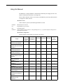
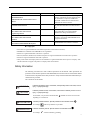
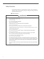
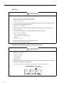
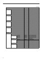
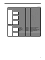
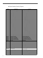
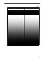
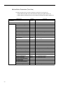
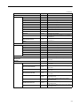
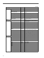
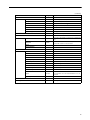
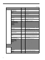
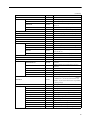
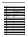
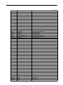
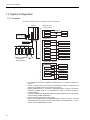
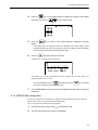
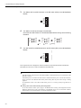
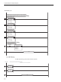
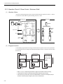
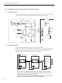
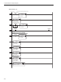
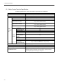
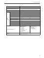
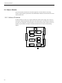
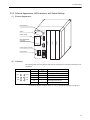
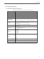
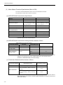
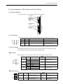
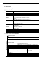
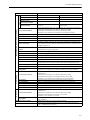
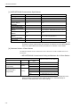
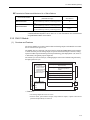
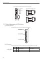
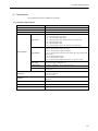
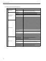
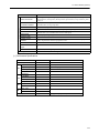
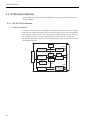
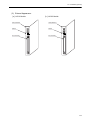
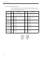
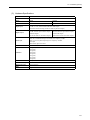
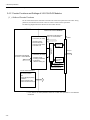
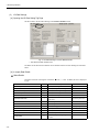
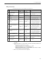
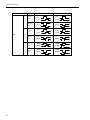
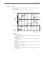
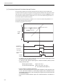
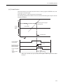
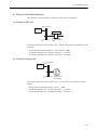
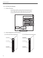
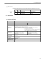
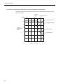
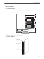
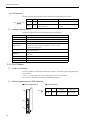
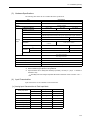
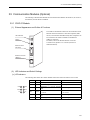
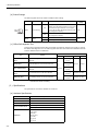
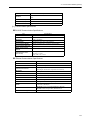
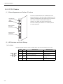
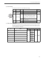
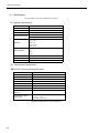
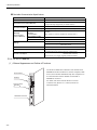
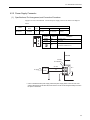
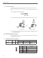
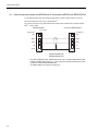
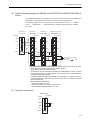
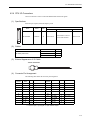
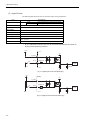
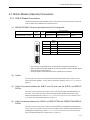
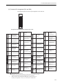
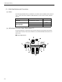
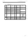
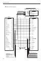
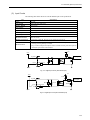
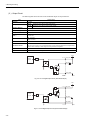
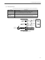
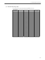
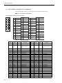
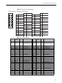
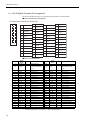
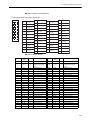
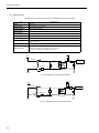
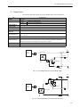
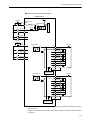
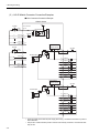
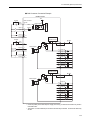
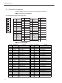
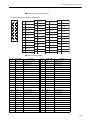
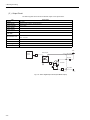
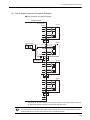
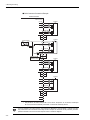
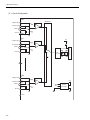
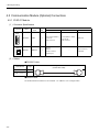
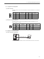
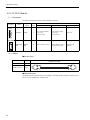
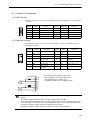
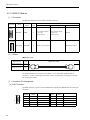
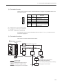
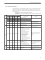
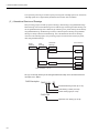
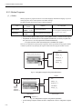
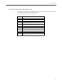
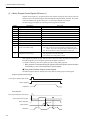
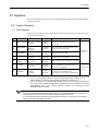
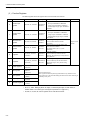
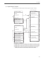
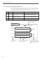
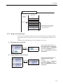
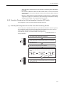
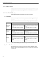
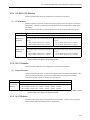
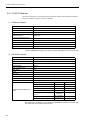
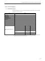
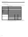
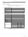
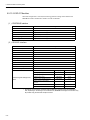
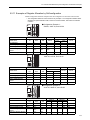
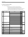
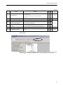
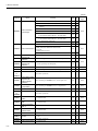
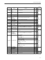
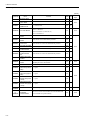
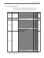
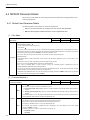
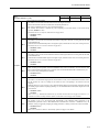
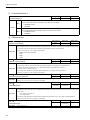
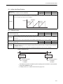
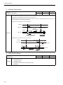
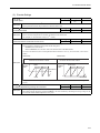
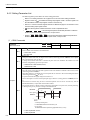
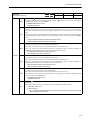
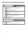
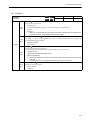
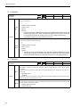
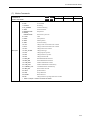
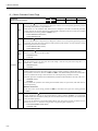
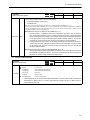
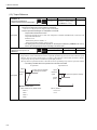
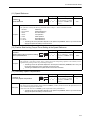
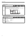
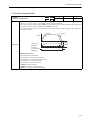
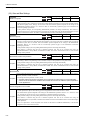
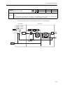
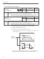
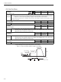
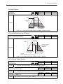
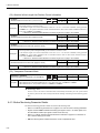
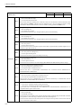
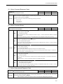
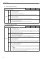
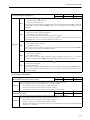
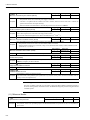
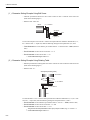
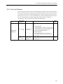
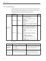
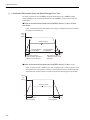
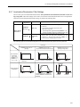
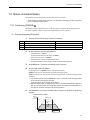
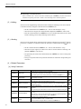
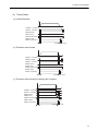
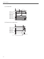
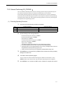
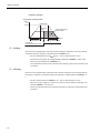
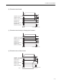
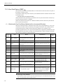
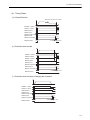
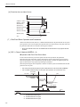
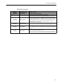
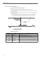
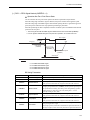
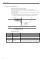
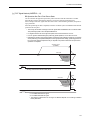
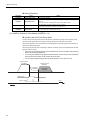
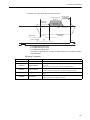
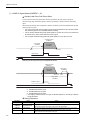
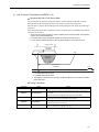
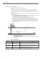
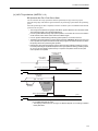
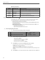
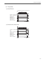
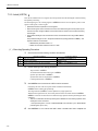
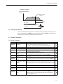
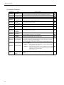
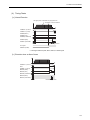
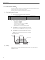
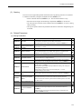
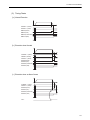
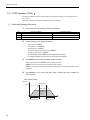
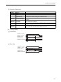
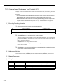
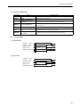
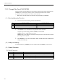
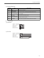
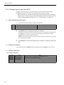
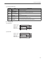
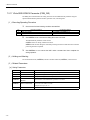
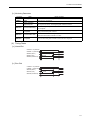
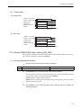
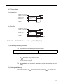
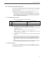
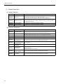
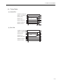
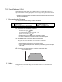
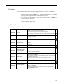
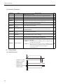
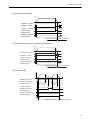
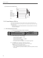
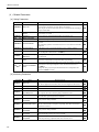
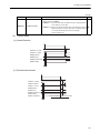
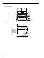
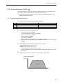
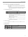
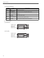
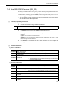
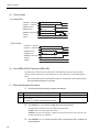
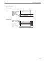
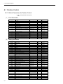
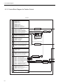
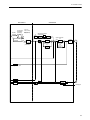
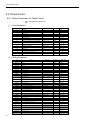
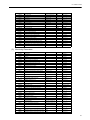
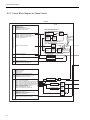
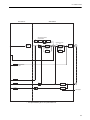
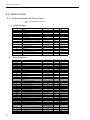
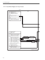
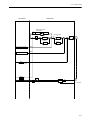
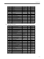
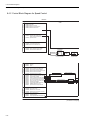
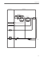
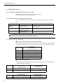
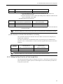
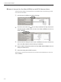
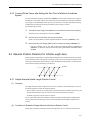
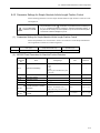
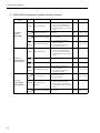
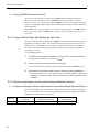
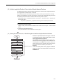
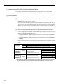
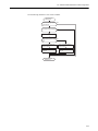
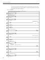
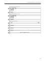
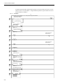
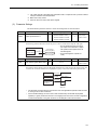
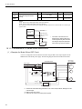
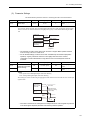
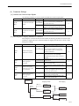
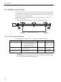
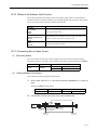
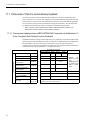
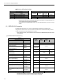
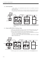
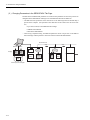
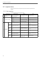
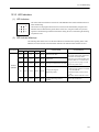
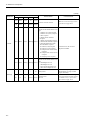
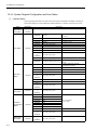
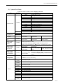
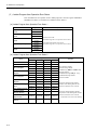
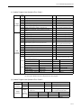
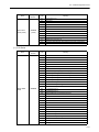
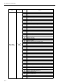
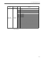
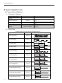
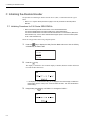
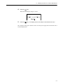
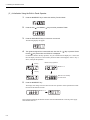
4 Mounting and Wiring 4.2.4 CPU I/O Connectors ( 5 ) Input Circuits The following table shows the CPU I/O Connector input circuit specifications. Item Specifications DI-00 General-purpose input (shared with interrupts) DI-01 to DI-07 General-purpose input Inputs 8 points Input Format Sink mode/source mode input Isolation Method Photocoupler Input Voltage ±24 VDC±20% Input Current 4.1 mA (TYP.) ON Voltage/Current 15 VDC min./2.0 mA min. OFF Voltage/Current 5 VDC max./1.0 mA max. ON Time/OFF Time ON: 1 ms max. OFF: 1 ms max. Number of Commons 8 points DI_00 is shared with an interrupt input. If DI_00 is turned ON while interrupts are enabled, the interrupt processing drawing is executed. +24 V +5 V DI_COM R DI_IN 5.6 kΩ/0.5 W R Input register R 0 24 0.01µF Fig. 4.1 Digital Input Circuit (Sink Mode Input) +24 V +5 V DI_COM R DI_IN 5.6 kΩ/0.5 W R Input register R 0 24 Fig. 4.2 Digital Input Circuit (Source Mode Input) 4-16