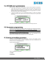
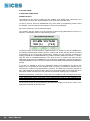
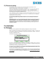
1
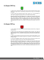
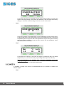
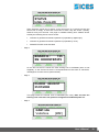
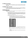
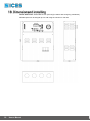
Filename: EAAM016305EN.docx Rev. 05 Date: 29/05/2013 ID Document: EAAM0163 Product: DST2600 1 Forward ......................................................................................................................... 4 2. Handbook validity .................................................................................................... 4 2.1 Firmware version .................................................................................................. 4 3. About safety ............................................................................................................. 5 3.1 Safety ground connection ..................................................................................... 5 4. CONNECTIONS ........................................................................................................ 6 4.1 Power line connection........................................................................................... 6 4.2 Load wiring ........................................................................................................... 6 5. Battery charge maintainer ...................................................................................... 6 6. Protections and internal fuses ............................................................................... 7 6.1 Battery protections ................................................................................................ 7 6.2 Phase line protections .......................................................................................... 7 7. Front panel breakers ............................................................................................... 8 8. Frontal panel description ........................................................................................ 8 8.1 Frontal panel view ................................................................................................ 8 8.2 LED lights ............................................................................................................. 9 8.2.1 Genset working modes indication ................................................................... 9 8.2.2 Visualization modes and warning/alarm lights ................................................ 9 8.2.3 MAINS LIVE light ............................................................................................ 9 8.2.4 Generator live/ engine running light (GENERATOR/ENGINE) ..................... 10 8.2.5 Change over status lights (KM/KG) .............................................................. 10 8.3 Key switches ....................................................................................................... 10 8.3.1 Cursor keys (arrows UP and DOWN) .......................................................... 10 8.3.2 MODE/ACK key............................................................................................ 11 8.3.3 AUX/PROGRAM key .................................................................................... 12 8.3.4 Changeover selection KM/KG ...................................................................... 12 8.3.5 Engine START key ....................................................................................... 13 8.3.6 Engine STOP key ......................................................................................... 13 8.4 Multifunctional display......................................................................................... 14 8.4.1 Internal display backlight .............................................................................. 14 8.4.2 Visualization modes ..................................................................................... 14 8.4.2.1 MODE 1................................................................................................ 14 8.4.2.2 MODE 2................................................................................................ 16 8.4.2.3 MODE 3................................................................................................ 17 8.4.2.4 MODE 4................................................................................................ 18 9. Clock ....................................................................................................................... 20 10. ii Test (engine starting test) ..................................................................................... 20 10.1 Manual command ......................................................................................... 21 10.2 Digital input command .................................................................................. 21 10.3 Periodical test ............................................................................................... 21 10.4 Command from serial port ............................................................................ 22 User’s Manual 10.5 SMS command ............................................................................................. 22 11. Working sequences ............................................................................................... 22 11.1 Genset protections ....................................................................................... 22 11.2 Protections disabling .................................................................................... 22 11.3 Working modes ............................................................................................ 22 11.4 Mains ............................................................................................................ 23 11.5 Generator ..................................................................................................... 23 11.6 Inhibition of automatic genset operations ..................................................... 23 11.7 Engine .......................................................................................................... 24 11.8 Engine commands ........................................................................................ 24 11.9 Manual start.................................................................................................. 24 11.10 Automatic start and stop ............................................................................... 25 12. Change-over logic ................................................................................................. 25 13. Load management ................................................................................................. 26 14. DST2600 start up initialisation.............................................................................. 27 15. Parameters programming ..................................................................................... 27 15.1 Entering and modifying parameters .............................................................. 27 15.2 Password setting .......................................................................................... 29 16. Anomalies .............................................................................................................. 29 16.1 Forward ........................................................................................................ 29 16.2 Anomalies signalling organization ................................................................ 30 17. TECHNICAL CHARACTERISTICS ......................................................................... 30 17.1 Fundamentals............................................................................................... 30 17.2 Current absorption ........................................................................................ 31 17.2.1 Battery current absorption with no mains voltage ................................... 31 17.2.2 Mains absorption ..................................................................................... 31 18. Dimensions and installing .................................................................................... 32 User’s Manual iii 1 DST2600 is an integrated automatic mains failure control panel equipped with all the devices and functions needed for such applications, included battery charge maintainer and siren. Generator currents and voltages measurements are done with true Root Mean Square method, mains voltages with means value. Images, drawings and some descriptions in this document can be related to versions of the device provided with one or more options. The present document is applicable starting from FW rev. 00.01. Information about DST2600 firmware revision can be obtained in two different ways:: A label on device identifies the serial number, the installed options and other information. This label also reports the software revision identified by the writing “FW” or “SW” followed by a numeric code “0085XXYY” or “0141XXYY”. When the device is powered, on the multifunction display will appear for about 3 seconds the following message: SICES s.r.l. DST2600 revXX.YY In both cases, XX is a two digit number the identifies the major software version, YY is a two digit number that identifies the minor software version. The complete device SW code is EB0220085XXYY or EB0220141XXYY. If the software revision is 00.06 (or 0.06) the actual code SW is EB02201410006. Inside this document, a vertical bar on the page right edge highlights some change in the paragraphs since the previous document version. Change in table fields are highlighted by a grey background. The list of the changes is in page ii. To improve the product, SICES, during the time, will introduce some changes in the products. In spite of every effort made to maintain updated the documentation, some new features or function couldn’t be covered by this document. In any case, check first for an updated version of the document on our website http://www.sices.eu/ ; if you need technical support, please write to [email protected] 4 User’s Manual Icon highlights prescriptions related to the safe use of the device. Please carefully read the present handbook before install or use the device. The device must be positioned and installed in such a way to drain off the heat it generates; avoid occluding the vent-holes. Don’t expose directly the device to inclemency of the weather or to ambients saturated with atmospheric humidity or saline. When working in “AUTO” mode, the genset can automatically start at any moment. CAUTION: TO AVOID ELECTRICAL SHOCK, THE FRONTAL PANEL REMOVING AND ALL THE OPERATION INSIDE THE PANEL MUST BE CARRIED OUT EXCLUSIVELY BY AUTHORIZED PERSONNEL AND ONLY IF MAINS SOURCE IS DISCONNECTED, THE GENSET ENGINE IS NOT RUNNING AND ENGINE STARTING BATTERY DISCONNECTED. Safety ground connection is MANDATORY and required for the proper device functionality. It must be done before any other connection; SICES srl is no in any way liable for damage or person injury due to the lack or the incorrect safety ground connection. Connection is made by a 6MA bolt on the panel internal bottom; it is highlighted by the following symbol The wire used for safety ground connection must have at least the same cross section as the power cable. User’s Manual 5 A magnetic-thermal over-current breaker or security fuses on mains line are mandatory and they are to the system installer care; the same for the generator lines in the version provided without the internal over-current breaker. Load wiring must be made on the most right contactors marked as “KG” (a label “LOAD LINE” is placed on the panel bottom). Connections have to be made in parallel to the wires that connect “KM” and “KG” contactors together. Starting from left to right, terminals are the followings: N (neutral) L1 L2 L3 For single-phase systems, connect neutral to terminal N and phase to terminal L1. REMARK: the wiring cross section to be used for generator power lines is 16mm2 for 40kVA applications DST2600 is equipped with a charge maintainer that has the purpose of supply the internal logic and compensate the self discharge of the main engine battery. It is supplied from phase L1 of the mains line; it is thus required that in three-phases system the neutral line is connected in order to proper supply the battery maintainer. A green LED, named “CHARGER ON”, quite in the middle of the interface board, signals that it is properly working. In stand-by mode it is able to supply to the battery about 650mA plus the current required to supply the internal logic. Even if the system is only a charge maintainer, it can charge the battery in constant current mode up to a voltage of 13.5V. 6 User’s Manual DST2600 has over-current protection for the battery connection and for the mains and genset connections. They are made by fuses. Before change any fuse, check that no harmful voltages are present: stop the genset by emergency stop, open the mains line and disconnect the genset battery. Replace them only with the same fuse types as those listed below. There are: - One ATO (or AL) fuse of 35A: it is connected between the battery and the power outputs “START” and “FUEL”. It fuses in case of overload on these outputs. - An auto resettable fuse of 5A is inserted between the positive battery and the panel supply: it open in case of panel failure or polarity inversion or overload at the auxiliary relay output J200-7. If mains is present, the opening of the fuse doesn’t shutdown the panel that is supplied by the charge maintainer; if mains is not present that panel will shutdown. Do not overcharge the auxiliary output J200-7 (max. 3A). - An auto resettable fuse of 2.5A acts as charge maintainer protection. It opens in case of hardware failure. - Two auto resettable fuses of 2.5A and 5A, to protect the auxiliary outputs at battery voltage respectively J405 and J406 Auto resettable fuses work as thermal switch and don’t require any operator procedure: remove the overload source and wait for protection cooling down. Each line input, both mains and generator, has a protection fuse. The fuse type is a 5x20mm, 1A and it is used to protect against internal faults. Only exceptions: fuse F203 on mains phase L1 and F200 on generator phase L1 are 2A fuses. The reason is that F203 output supplies the contactor “KM” and the charge maintainer. F200 supply the contactor “KG”. To summarize: 4 5x20mm fuses of 1A: F201, F202, F204, F205 2 5x20mm fuses of 2A: F200, F203 The fuse of one of this protection yields a measurement error, like the phase missing. In auto mode, the opening of one of the fuses placed as mains line protection (F203, F204, F205) will cause the genset start for mains failure; F203 will cause, in addition, the switch off of the charge maintainer and the drop of “KM” changeover (so loads will be no more supplied by mains). The opening of one of the fuses placed as generator line protections (F200, F201 and F202) will cause in “AUTO” mode an anomaly activation upon the generator status (“operating condition failure”, “under-voltage” or “under-frequency” depending by the opened fuse and when the failure appears); in manual mode there isn’t any signalling of anomalies but the changeover on genset is not allowed since the generator is not seen in the “ready to supply” window . User’s Manual 7 On the front panel there is normally a thermo-magnetic breaker to command and protect the engine warming resistor (if present). In some version it can be substituted with a breaker on the device supply at battery voltage, with the rule to disconnect the device when its use is not scheduled. The upper part of the control panel is made of polycarbonate, resistant to oil and solvents, which has symbols and identification strings. Here there are all the commands, the alphanumerical signalling and the warning lights; these will be described in details in the following paragraphs. The frontal panel can be different in the graphical aspect with respect to the one shown here; however the functions of the keys, the warning lights and of the display stay unchanged 8 User’s Manual DST2600 has eleven lights, to signal status, events and for the working and visualization modes. In the “OFF_RESET”, by pressing the “STOP” key, all the lights will be lighted on (“LAMP TEST”) allowing to check their proper working. They’re three yellow lights on the left side of the arrow keys. They signal the working mode of the device (for a complete description of the working modes see par. 8.3.1). The third lamp signals both the “AUTO”, “REMOTE START” (if fixed) and the “TEST” modes (if flashing). They are four yellow lights, on the right side of the multifunctional display. They show what is the actual visualization of the display; press the “MODE/ACK” key to scan the four modes. The “MODE 2 WARNING” light also flashes when a warning arises (an anomaly that doesn’t cause the engine shutdown); the “MODE 3 ALARM” instead flashes when a block or a deactivation has occurred. When a new anomaly occurs (of any type) the display visualizations is forced to “MODE 1”, allowing the visualization of the description of the anomaly. It is however possible to select any other mode, also with one or more anomalies pending. The “MAINS LIVE” (green) light shows the mains status. It has the following meanings: OFF: mains not present. Flashing: the mains is present but the voltage on one or more phases is not between the programmed tolerance thresholds (or they are but from a time shorter than the one configured); if loads are changed over on generator, they must stay on it. Furthermore, the light signals also the genset inhibition status (see par. 11.6). If the inhibition status is active, the light flashes also if mains is present. ON: mains is steady present between its tolerance thresholds and so loads can be changed over on it. User’s Manual 9 The “GENERATOR/ENGINE” (green) light shows the engine and generator status. It has the following meanings: OFF: if the devices diagnoses the “ENGINE STOPPED” status Flashing: if the devices diagnoses the “ENGINE RUNNING” status but the generator frequency and/or voltages aren’t between their tolerance thresholds ON: if generator frequency and voltages are steadily between their tolerance thresholds The two lights (green) show if the loads are supplied by mains (“KM”) or by generator (“KG”). The device has seven key switches; each of them has associated one or more function, depending on the context. With the “UP” and “DOWN” keys it is possible to select the genset working mode (“OFF_RESET”, “MAN”, “AUTO”). Each mode is signalled with the corresponding light. To pass from one mode to another, keep pressed the arrow key for about one second; to pass from “OFF_RESET” to “AUTO” and vice-versa it is necessary to pass from “MAN”. In details: a) “OFF_RESET”: in this mode the board is switched on but all the genset control and management functions are excluded. This is the mode to use when the automatic genset starting is not required (for instance, to avoid automatic starting, useless during a factory 10 User’s Manual closing time, etc.) and above all as security position for genset maintenance. When the “OFF_RESET” mode is selected the genset cannot start if mains fails. The mains switch is forced at work and so loads are supplied from mains (if mains is present). In any case the surveillance on mains, generator and engine status, and the display visualizations are active. When the “OFF_RESET” status is selected, the following operations are carried out: 1) The loads changeover is forced to mains (if loads were supplied from generator). 2) The engine shutdown sequence is activated (if the engine was running). 3) Reset of all the eventual memorized anomalies that caused the genset shutdown. In this mode the battery charger is in any case active In “OFF_RESET” mode (and only in this mode) it is possible to visualize and change the device programmable parameters. b) “MAN” (MANUAL): in this mode the board is ready to manage a manual use of the genset. In brief: 1) The manual start and stop procedure are enabled, where the automatic procedure are disabled (so the engine won’t never start automatically by the board). 2) It is possible to changeover the loads on generator with the explicit command of the operator (only if the generator is in the proper condition to supply). The changeover won’t never be done by the board (except the changeover to mains if a block or a deactivation arises) No action upon engine and changeover will be made when passing from “AUTO” to “MAN”: the engine maintains its status (running/stopped) and loads too (on mains/on generator). It is only stopped the eventual start attempt in progress. c) AUTO (AUTOMATIC): this is the normal working mode of the board. In this mode the engine is started/stopped automatically when mains fails or with regular intervals to keep the genset efficient. In the same way loads are automatically changed over on mains or generator, according to the conditions of both of them. REMARKS: when the AUTO mode is selected, it is forbidden every kind of maintenance on genset. In this mode is furthermore possible to run a manual “TEST”, besides the automatic periodical running test (see par. 10). Moreover, it is possible to pass to “REMOTE START” mode, by a digital input command or by a serial port command. The “MODE/ACK” allows to select the visualization on the multifunctional LCD display (see par. 8.4.2). Pressing one time the key, the visualization mode passes to the next in a cyclical way (from “MODE 4”, pressing the “MODE/ACK” the display visualization will come back to “MODE 1”). User’s Manual 11 If the key is pressed together with the “AUX/PROGRAM” key, it allows the manual regulation of the display’s contrast level (this regulation is available only for some display models and only from software version 00.03; with previous version this keys combinations allows to stop the generator phases scanning on the phase visualized on display at the moment). The key allows moreover to “acknowledge” the anomalies by the operator, stopping the internal horn. NOTE: the horn is silenced when the key is released. During the parameters programming (see par.15) the key works as “ENTER” allowing to “enter” in menu and sub-menu, to start the modify operation of a parameter and to confirm the new selected value. The “AUX/PROGRAM “ allows scanning all the windows related to a visualization mode of the multifunctional display currently selected. Press the key to pass to the next window of the mode, in a cyclical way. If the key is pressed together with the “MODE/ACK” key, it allows the manual regulation of the display’s contrast level (this regulation is available only for some display models and only from software version 00.03; with previous version this keys combinations allows to stop the generator phases scanning on the phase visualized on display at the moment). If “MODE 1” visualization (which has only one window) is selected and the device is not in “OFF_RESET” mode, the key hides the description of a pending anomaly, in such a way to allow the visualization of the power measurements. If “MODE 1” visualization is selected and the device is in “OFF_RESET” mode, the key allows to enter in the parameters programming procedure. During the parameters programming the key is used as “EXIT”: it allows to exit from sub menu to return to the upper level menu; press it from main menu to exit from programming procedure. The key allows moreover to abort the modification of a parameter when in progress (the parameter will keep its previous value). The key finally allows, if used together with the “START” and “STOP” keys to modify the value of a parameter of 10 units at time (“SHIFT” function). When the genset is running in “MAN” or “TEST” mode, the key “KM/KG” allows, with proper generator conditions, to changeover the loads from mains to generator and vice-versa. It has no effect while working in “AUTO” and “REMOTE START” modes. 12 User’s Manual - In “MAN” the key command the engine start; the key must stay pressed until the engine will start. The engine starter is automatically released when the engine is acknowledged as running. - In “AUTO” mode, the key starts the manual “TEST” (see par. 10.1). This is possible only if the engine is stopped with mains present or with inhibit contact activated. - During the parameters programming the key is used to scan the menu items in the increasing direction. During the modification of a parameter it increases the parameter value: each pressure increases the value of one unit. Keep the key pressed to automatically increase the value; it will restart from its minimum after the maximum will be reached. Used together with the “AUX/PROGRAM” key (press and keep pressed “AUX/PROGRAM” first and then use “START”), each pressure increments the value of 10 units. - In “OFF_RESET” press this key to switch on all the LED lights (“LAMP TEST”), to diagnose possible failures. - In “MAN” mode, when pressed the key immediately stops the engine; if the load was supplied from generator, it is immediately changed over on mains before commanding the engine stopping. It is not necessary to keep pressed the key until the engine will be stopped. - In “TEST” mode, pressing the key the test ends; that is the engine will be stopped, in case after the cooling time if the load was changed over on generator, and the device will return to “AUTO” mode. - In “AUTO” and “REMOTE START“ modes, press the key to execute an emergency stop of the engine, signalled with the block “A007-STOP PRESSED IN AUTO”. - During the parameters programming the key is used to scan the menu items in the decreasing direction. During the modification of a parameter it decrease the parameter value: each pressure decreases the value of one unit. Keep the key pressed to automatically decrease the value; it will restart from its maximum after the minimum will be reached. Used together with the “AUX/PROGRAM” key (press and keep pressed “AUX/PROGRAM” first and then use “STOP”), each pressure decrements the value of 10 units. User’s Manual 13 The multifunctional display is the means to visualize measures, status indications, and alphanumerical anomalies. The visualization is on two rows and sixteen columns. The contrast level can be manually regulated by pressing the keys “MODE/ACK” and “AUX/PROGRAM” at the same time: if you first press “MODE/ACK” the contrast level increases, if you first press “AUX/PROGRAM” the contrast level decreases. The regulated level is stored in non-volatile memory and so it is preserved even if power supply is disconnected. ATTENTION: the manual contrast regulation is available only from software release 00.03. On some board is mounted a display with automatic contrast regulation: in this case the manual regulation has no effects. The display has an internal backlight, which allows the reading of the indications also in bad light condition or at night. The internal lamp is switched on pressing any key; its turn off can be configured with the parameter P.492: it is the maximum working time (in seconds) of the lamp since the last key was pressed. Setting the parameter to zero to leave the lamp always on. NOTE: if the lamp is switched off, the pressure of a key causes only the switching on of the lamp and doesn't involve the action predefined for the key: to obtain this action the key must be pressed again. While the engine starter is running, the lamp is automatically switched off to reduce the current consumption of the board, in such a way to leave more energy to the board if the engine battery voltage is low. When the engine is running (only if started by DST2600), the light is always switched on to improve the readability of the display The display foresees four visualization modes, selected with the “MODE/ACK” key and highlighted by the four LEDs on the right side of the display. Except for “MODE 1”, each mode has more than one page: it is possible to select these pages with the “AUX/PROGRAM” key. Passing from one mode to another, the display shows as first the last page visualized in that mode. L1 400 10.1 50.0 6.97 0.0 1.00i In this mode are usually shown the fundamental electrical measurements of the generator. 14 User’s Manual Phase: in the left side of the first row there is the indication of the phase (phase L1 in the example) to which the voltage and current visualized in the rest of the row are referred. With single-phase systems the phase indication is always L1. With threephases systems the phase shown changes cyclically following the order L1, L2 and L3. ATTENTION: only with software release lower or equal to 00.03 is however possible to force the visualization of one phase pressing together in the order the “AUX/PROGRAM” and “MODE/ACK” keys: the visualization is halted and so the present phase stays visualized. In this condition the phase indication flashes. Generator voltages: again, on the first row is shown the generator voltage expressed in volts. Voltages are visualized with maximum three digits, with no decimals. If the value is lower than 10V the visualization is forced to zero. For three-phases systems it is shown the phase-to-phase voltage: o L1-L2 if it is currently visualized the phase L1. o L2-L3 if it is currently visualized the phase L2. o L3-L1 if it is currently visualized the phase L3. For single-phase systems it is visualized the phase–to-neutral voltage. Generator currents: in the first row, in the centre, it is shown the current measurement of the phase currently visualized, expressed in Amperes. It is visualized with two decimal digits if lower than 10 amps, otherwise with only one decimal digit. If the value is lower than 0.66A for 20kVA version or 1.2A for 40kVA version, the visualization is forced to zero. Generator frequency: in the right side of the first row there is shown the frequency of the generator voltage, always related to the L1 phase. It is expressed in hertz and is visualized with a decimal digit. Active power: in the left side of the second row there is the indication of the total active power supplied by the generator, expressed in kW. In case of power reverse, the active power has negative sign. If the currents values (or voltages values) drop lower than their visualization thresholds (see above), the visualization is forced to zero. Reactive power: in the centre of the second row there is the indication of the total reactive power supplied by the generator, expressed in kvar. Power factor: on the right side of the second row there is the indication of the total power factor of the load connected to the generator. To its right there is the “i” letter if the load has inductive characteristics or the “c” letter if capacitive. Normally the indication is with one integer and two decimal digits; if the currents drop lower than 1/10 of their full scale value (that is 3.3A for 20kVA version and 6.2A for 40kVA version) the power factor is forced to one. In the case of power reverse the indication is preceded by a minus sign and the integer digit is not shown. If the engine is in a transitory phase (starting, stopping, cooling, that is the engine is not neither in running nor in stopped status) the first row alternates the visualization of the electrical measurements seen above with the description of the present engine status. The possible indications are: "STOP CYCLE ": the engine is stopping. "ABORT STOP ": the stop cycle is interrupted for a new start request. "ENG. NOT STOPPED": the engine is not stopped after a stop cycle. "PREHEAT": it is active the glow plugs command foe Diesel engines, awaiting the real start. User’s Manual 15 "FUEL SOLENOID ON": the “FUEL” command is active but the “START” command not yet. "CRANK IN PROGR.": the “START” command (engine starter) is active for the engine crank. "DELAY": one crank attempt was not successful and it is in progress the pause before next attempt. "CHECK FOR RUN": the “START” key, in MAN mode, has been released before the engine was really running; the device waits some seconds to check if the engine really starts or it dies. "WAIT FULL SPEED": the engine is running; the devices is waiting that the generator electrical measurements reach their proper tolerance thresholds. " COOLING ": cooling cycle in progress "CLEANING": washing cycle in progress. " WAITING FOR STOP": stop cycle in progress, excitation engine stop time elapsed. " IDLE SPEED.": the engine is running but it is active the idle speed command. With these visualizations, keep pressed the “AUX/PROGRAM” key to hide the engine status and to show the generator electrical measurements. Some of the status above described take place only if programmed on purpose (i.e. “cleaning” or “idle speed”) If any anomaly is present, on second row there is the description of the anomaly/anomalies pending. The description of the anomaly slides on second row; if more than one anomaly is active, they are visualized cyclically. In this situation, keeping the ”AUX/PROGRAM” key pressed the anomalies are hided and the power measurements return visible. Only if the device is in “OFF_RESET” mode, press the “AUX/PROGRAM” key to enter in the parameter programming procedure. Whatever is the visualization mode, when an anomaly occurs the visualization is forced to “MODE1”. In “MODE2”, pressing more time the “AUX/PROGRAM” key, it is possible to visualize four different pages, containing measurements related to generator and to mains - Page 1: Total kVA: 10.1 Phase sequence: -On the first row is shown the total apparent power expressed in kVA. On the second row, with three-phases systems, there is a text showing the phase sequence of the generator (CW = clockwise / CCW = counter clockwise). If the system is configured as single phase, the text is substituted with dashes (as in the example). - 16 User’s Manual Page 2: 1 0.0kVA 0.0kW 1.00i 0.0kvar This page is shown only with three phases systems. It shows the powers related to each single phase, cyclically. In the first row it is shown the present phase (1 in the example), followed by its apparent phase power (in kVA), by its power factor and by the indication of the type of its load (i if inductive, c if capacitive). The second row shows the active power (in kW) and the reactive power (in kvar) of that phase. If the active power and the power factor have negative sign, the system is working in a power reverse situation. NOTE: if in “MODE1” the phases scansion is halted, this page will result halted too. - Page 3: kWh: kvarh: 13 1 In the first row it is shown the total active energy supplied by the generator (in kWh). In the second row it is shown the counter of the total reactive energy supplied by the generator, in kvarh. - Page 4 MAINS R S T Hz 399 398 396 50.0 On the second row are shown the three mains phase-to-phase voltages, L1-L2, L2L3, L3-L1. The measurements are in volts wit no decimals. For single-phase system, the second and the third measurement are substituted with dashes, and the first shows the phase-to-neutral voltage. On the right side there is shown the mains frequency, in hertz, with one decimal digit. In “MODE 3”, pressing more times the “AUX/PROGRAM” key, it is possible to visualize three different pages containing measurements related to the engine: - Page 1: User’s Manual 17 START#/ BATTERY 224 13.4Vdc On second row there are visualized the total engine starts number (only when the engine was really started), both manual and automatic, and the engine start battery voltage, in volts with one decimal digit. The start counter can be reset - Page 2 HOUR ABS/PAR/MIS 51 48 ------- On second row there are visualized three counters related to the engine running hours. On the left side there is the total engine running hours (absolute hours), in the centre the partial engine running hours and on the right side the engine running hours missing before the engine maintenance (this function must be set with parameter P.424, otherwise dashes are shown). - Page 3 Bar 3.8 °C 82 Lev% 32 On second row are shown in the order: the engine oil pressure (in bar), the coolant temperature (in °C) and the fuel level (as percentage with respect the full tank). These measurements are available only if engine instruments were been properly configured. If one or more measurement is not available because not configured, the indication is substituted with dashes In “MODE4”, pressing more time the “AUX/PROGRAM” key it is possible to visualize four different pages: - 18 User’s Manual Page 1 STATUS Inhib. From I/O Some particular events can be shown on the second row. If no events is active, the second row is empty. If more than one event is active, they are shown cyclically, switched every two seconds. This page is available starting from software 00.06. Actually the following events can be shown: - Inhibition of generator automatic operations (requested by digital input). Inhibition of generator automatic operations (requested by clock). REMOTE START mode activated Page 2 BOARD H.: 135 SN: 000009FBF4F9 On the first row there is shown the total working hour of DST2600 (since it was supplied), on the second row there is an alphanumerical code with 12 characters, unambiguous for each device (serial number) - Page 3 CLOCK 08:29:57 31/01/2008 This page shows the internal clock of DST2600 (see next). Date and time are flashing if the clock have not yet been configured from DST200 power on. - Page 4 GSM: idle Vodafone [### ] User’s Manual 19 The first row shows the communication resource presently connected to the serial port. The indication can be: - RS232: if there is a RS232/RS485 connection. - Modem: to the serial port it is connected an analogue modem. The rest of the row shows the modem status (at rest, incoming call, outgoing call etc.). - GSM: to the serial port it is connected a GSM modem. The rest of the row shows the modem status (at rest, incoming call, outgoing call etc.). The second row shows the GSM service provider’s name and the present signal level (from one to four notches). DST2600 manages an internal clock/calendar. Attention: there isn’t any internal real clock circuit, so if you remove power supply from DST2600, when you power it again the date will be “01/01/2000” and the time will be “00:00:00”. In this case, date and time are marked as “not valid” (in some cases this situation causes the activation of a warning signaling). Date and time are marked as “valid” only when you change them (or a part of them), even if you simply confirm actual values. You can change date and time by the serial port (SicesSupervisor PC software) or manually by the standard parameter programming function: the year, the month, the day etc are normal configurable parameters of DST2600. The clock is used for two main functions: Periodical test. Inhibition of automatic genset operations in predefined time intervals. Both functions will be explained in the next paragraphs. DST2600 allows to execute genset running tests, in such a way to check its efficiency and to assure the lubrication of the engine internal parts. The test can be run: On operator direct command (on START key). From digital input command. Automatically with regular intervals. From serial port command. From SMS command. To run the test, DST2600 must be in “AUTO” mode. If while the test is running there is a mains failure and there are the proper conditions on generator frequency and voltages, the device does the changeover of the loads and comes back to its normal AUTO working mode. While the test is running, with the proper generator condition on frequency and voltages, pressing the “KM/KG” key the loads are changed over from mains to generator and vice-versa. 20 User’s Manual Pressing the “START” key with DST2660 in “AUTO” mode the device begins the automatic cranks sequence. Press the “STOP” key to end the test, coming back to the normal automatic working mode. It is identical to the manual command but the command is given activating one digital input, previously configured for this function. In this case, to end the test it is necessary to deactivate the input (pressing the “STOP” key will cause the activation of a block). To enable the periodical test it is necessary to set the some parameters. The procedure is changed from revision 00.06 of DST2600. Up to 00.05 version: parameters involved are P.419 and P.420. Parameter P.419 is a time expressed in hours: it is the time interval between one test and the next. This time is computed from the beginning of the previous test (the length of the test has not influence over its repetition time). The parameter P.420 is a time expressed in minutes and it is the length of the test. From 00.06 version: parameters involved are P.418, P.419 and P.420. o P.418: by this parameter you can select one ore many days of the week. In these days, the periodical test will be performed. If you set the parameter to zero, no periodical test will be done. Each day is associated with a numerical value: you must set P.418 with the sum of the values related to the desired days. Day 1. Value 1. Sunday 2. 1 1. Monday 3. 2 1. Tuesday 4. 4 1. Wednesday5. 8 1. Thursday 6. 16 1. Friday 7. 32 1. Saturday 8. 64 For example, if you set P.418 as “42”, the periodical test will be carried out on Monday, on Wednesday and on Friday (because 42 is the sum of 2, 8 and 32). o P.419: by this parameter you can select the starting time for test (from 00:00 to 23:59). o P.420: is the length (in minutes) of the test (if zero the test will never be performed). User’s Manual 21 It is identical to the manual command but the command is given from the serial port (from a PC or other devices). To end the test it is necessary to give the opposite command to the device (pressing the “STOP” key will cause the activation of a block). If the serial connection breaks off while running the test, the device comes back to its normal automatic working mode. The operator can start a test by sending a SMS containing a specific text (see SICES document EAAS0180xx). In the same way the test can be ended. NOTE: the test can be started in this way only if the parameter P.429 (test length) has a value different from zero: this because there is no certainty to receive the SMS which ends the test, and so it is necessary to use this parameter as maximum test length over which the test is anyway interrupted. DST2600 has many protections, for the safeguard of both the engine and the generator. Some of them are defined as limit value of their related measurements, some other as percentage with respect to a minimal value. Following the system implementation or the type of intervention that they have, the modality to disable the protections changes: it can be necessary to set a particular value in a threshold value or simply to deselect the protection itself. In the document EAAM0147xx (parameter list) there is a complete list of the parameters and of the value to insert in them to disable each single protection (“values for disabling the protections”). It may be necessary to have the password to accede to the parameters programming. DST2600 has five working modes, selectable with the cursors keys (see par. 8.3.1) and with the “START” and “STOP” keys: 22 User’s Manual “OFF_RESET”: the genset is stopped (or in the stopping phase), all the anomalies are reset and it is possible to enter in the programming procedure to changes the parameters. “MAN”: the engine start and the loads changeover are managed by the operator (the device won’t never do automatically these operations). Normally the operator has do the engine stop and the loads changeover on mains; since protections are enabled, the devices can anyway changeover the loads on mains if the generator is non in its tolerance window and in the same way can stop the engine if an anomaly requiring it occurs. “AUTO”: the engine start and stop, besides the loads changeover, are managed by the device (the operator cannot takes part). All the protections are enabled. “TEST”: this working mode is almost identical to the “AUTO” mode. It differs in the fact that the engine is in any case started (automatically) by the board also in the mains is present. However the operator can manually changeover the loads. The board passes automatically to “AUTO” mode if the conditions for an automatic intervention of the genset are verified (mains failure). For more details about TEST mode see par. 10). “REMOTE START”: this working mode is almost identical to the “AUTO” mode. It differs in the fact that the engine is in any case started (automatically) by the board also if the mains is present. The loads are automatically connected to the generator and the operator cannot take part on this actions. This working mode cannot be activated from “OFF/RESET” and “MAN” mode. In “AUTO” or “TEST” mode, it can be activated in two different ways: o The command is given activating one digital input, previously configured for this function (the input has to be configured as “27 - Remote start request”. In this case, to back to the “AUTO” mode it is necessary to deactivate the input. o The command can be sent over the serial port or by an SMS. In this case, the command can be accepted only if one digital input of the board is configured as “29 - Remote start enable”, and this input is activated. When the input will be deactivated, the DST2600 immediately goes back to “AUTO” mode, even if it has not yet received the reverse command from serial port / SMS. DST2600 acquires the mains voltage of the plant (single-phase or three-phases), in order to command automatic engine starts and stops (and the loads changeover) in the case of failure upon the mains itself (AMF – Automatic Mains Failure). The mains status is highlighted by the “MAINS LIVE” LED (see par. 8.2.3). DST2600 acquires the voltage (single or three phases) and the generator frequency with the purpose to protect the loads and the generator from working out of the tolerance thresholds. If generator voltages and frequency are not in their tolerance bands, the load changeover to genset is not possible, also in “MAN” mode. For three-phases systems the frequency measurement is done on the phase-to-phase voltage L1-L2 It is possible to inhibit the automatic genset starting (for mains failure) in two different ways By setting a digital input as inhibition command (code “25-Inhibition”). This command is managed only in “AUTO” mode: when the input is activated, the engine will not automatically start for mains failure; if activated with engine running for mains failure, there will be a stop cycle. In practice it corresponds to a mains simulation. By selecting one or more days of week and one time interval (this option is available only from revision 00.06). The generator will be inhibited outside the selected time interval and on the non-selected days. This function must be configured by three parameters: o P.421 “Generator enable days”: by this parameter you can select one ore many days of the week (please see 10.3 for P.418 parameters setting, the same is for P.421). o P.422 “Generator enable start time”. User’s Manual 23 o P.422 “Generator enable stop time”. Into the days of week selected by P.421, the automatic genset operation are enabled only between the time interval starting at P.422 and ending at P.423. If P.422 and P.423 are set to the same value, DST2600 enables generator operations all the day (but only for selected days). If P.422 is later than P.423, the time interval is across midnight. When the automatic genset operations are inhibited, a message is shown on the “STATUS” page of “MODE 4” display mode. This command can be used to prevent the genset startup for mains faulty. The command has no effect in “MAN” mode and doesn’t prevent the starting for “TEST” and “REMOTE START”; its activation is signaled by the “MAINS LIVE” light, which flashes also with mains presence. DST2600 is able to start, stop and protect the engine with a series of thresholds upon the acquired measurements (oil pressure, coolant temperature, speed etc.). The engine running/stopped status can be acknowledged by means of the generator voltages, generator frequency, D+ (battery charger alternator excitation) and oil pressure signals, depending on the system configuration. The device manages two separated and direct commands for the engine management: “START”: engine starter command. “FUEL”: fuel solenoid command. It can be configured for drop down or excitation systems It is possible to manage other two commands only if the configurable outputs of DST2600 are properly configured: “PREHEAT”: glow plugs command. “ENABLE”: like “FUEL” (when configured as drop/down system), but it stays active also during stop cycle.. To start the engine in “MAN” mode, press and keep pressed the “START” key. The engine starter is automatically released when the engine is acknowledged as running. The engine starter is not commanded if the engine is already running. Press the “STOP” key to stop the engine. If loads are supplied by genset, pressing “STOP” they are changed over on mains before to stop the engine. 24 User’s Manual The automatic engine management is used in the “AUTO”, “TEST” and “REMOTE START” working modes (there are no differences in the engine sequence between these modes: the differences are only in the protections and changeover management). The engine is starter automatically if there are no blocks or disables and at least one of the following conditions is verified: The mains voltage is out of its tolerance thresholds and the start inhibition contact is not activated. The “TEST” mode is active (see par.10). The “REMOTE START” mode is active (see par. 11.3). In automatic mode the engine can be stopped in two ways: a) With normal procedure. This procedure consists of doing an engine cooling cycle (only if the load was been connected to the generator), keeping it running with no loads connected. This procedure is applied if: o No more automatic start request is pending (mains present and board in “AUTO” mode). o An anomaly, qualified as “deactivation” has occurred (it is an anomaly typically dangerous for loads but not for the genset). b) With an emergency procedure. This procedure requires the immediate engine stop, without engine cooling cycle. It is applied if: o When the “STOP/RESET” mode is selected o An anomaly qualified as “block” occurs. NOTE: in “AUTO” mode, if the “STOP” key is pressed it is activated the block “07-Manual stop in automatic”. Loads can be changed-over to generator only if all the following conditions are verified: o Generator voltages and frequency are in the tolerance band from a proper time. o The engine has been started by the board (the fuel solenoid command must be active). o No alarms or deactivations are present. In the OFF/RESET mode, loads are always changed-over to mains (and so, selecting this mode will cause an automatic changeover to mains if load was connected to generator). In the “MAN” mode, loads are usually changed-over to mains. Using the “KM/KG” button it is possible to invert the changeover status (the changeover to genset is possible only if the conditions previously seen are verified). NOTE: it is possible only to invert the status: it is not possible to leave open both the breakers. Passing from “AUTO” to “MAN”, the changeover status doesn’t change. In “AUTO” mode, the loads are changed-over on genset (with respect of the proper conditions) only when mains is out of the tolerance thresholds. As soon as mains comes back in tolerance, loads are newly changed-over on mains (with proper delay times, see the sequence of the mains). Passing from any other working mode to “AUTO”, loads are forced as described, driving a changeover if needed. The “KM/KG” button is ignored. This status uses another timing: to close the loads on genset it must be passed the P.218 time since engine started, or, more precisely, since the genset voltages and frequency are internal to their tolerance bands. User’s Manual 25 This delay is used mainly to give a minimum time to the engine to warm itself before supply the load In the “TEST” mode, loads are normally changed-over to mains. Passing from any other working mode to “TEST”, loads maintain their status. Using the “KM/KG” button it is possible to invert the changeover status (the changeover to genset is possible only if the conditions previously seen are verified). NOTE: it is possible only to invert the status: it is not possible to leave open both the breakers. For this status too the delays configured with P.218 are applied. It has to remember that the board passes automatically in AUTO (aborting TEST mode) if its automatic intervention is required. In “REMOTE START” mode, the loads are always changed-over on genset (with respect of the proper conditions). Passing from any other working mode to “REMOTE START”, loads are forced as described, driving a changeover if needed. The “KM/KG” button is ignored. P.218 is used in this status too. It has to remember that the board passes automatically in AUTO (aborting TEST mode) if its automatic intervention is required This function allows to monitorize the trend of the active power in order to diagnose a “low” or “high” load condition (selectable by P.481 parameter, 0 means “low”, 1 means “high”). The low/high status is signaled by a digital output configured as “4 – load function status”: if no output is configured in this way, this function is disabled. This function may be enabled/disabled with a digital input appositively configured (code “33load function enabled); if no input is configured with code 33, the function is always enabled. If, however, at least one input is configured in this mode, the “low” load survey is enabled after P.482 seconds from input activation. If power drops down for P.484 seconds under the threshold P.483 the “low load” status is detected, if it rises for P.486 seconds over the threshold P.485 the “high load” status is detected; in the other cases the status stays unchanged (histeresys). The output is activated when : 26 User’s Manual “low” load condition is detected if P.481 is set to zero. “high” load condition is detected if P.481 is set to one. When DST2600 is supplied (from engine battery or mains), is does a sequence of operations: LAMP TEST: the internal horn is enabled for about 0.5 seconds; all the LEDs and the display internal light are switched on for about two seconds. This operation has the purpose to allow to the operator to check for failures on the signal lamps or on the horn that could involve a lack in a failure signalling. It shows the firmware level. On the multifunctional display it is shown the message “revXX.YY” (revision). All the lights on the frontal panel are switched off. This phase lasts one second. SICES s.r.l. DST2600 rev00.01 When these operations are ended, the device starts to run its working sequences. DST2600 has many parameters that allow to adapt its working to many employment situations. The access to the programming procedure can be protected by a password set by the system installer. The parameters modification must be done exclusively by specialized personnel, because an error could compromise the intervention and the working of the genset, and also cause damages on the genset itself. The complete parameters list is on document EAAM0147XX; some parameters can be different from their default because already set-up for the specific plant. To enter in the programming procedure (“PROGRAM”), select the “OFF_RESET” working mode with the “UP” key, select the “MODE1” visualization mode with the “MODE/ACK” key and then press the “AUX/PROGRAM” key. The main menus list appears: [1 SYSTEM 2 SEQUENCE ] There are altogether 5 main menus: 1 SYSTEM 2 SEQUENCE User’s Manual 27 3 PROTECTIONS 4 AUXILIARY FUNCTIONS 5 INPUT/OUTPUT The selection of one menu is made with the “START” and “STOP” keys (“increment” and “decrement” functions); the square brackets show what is the selected menu. To enter in a menu, press the “MODE/ACK” key, which when in programming mode is used as “ENTER”, for both submenus and values to insert in the parameters. If there are submenus, use the same procedure. The “START” and the “STOP” keys are used also to skim trough parameters of a menu or a submenu. The display looks as in the following picture: 301-MIN. VOLTAGE THR (%) [75.0] The present value is shown between square brackets. To modify it, press the “MODE/ACK” key (square brackets begin to flash); with the “START” and “STOP” key the value is increased or decreased of one unit at time (continuously, keeping the key pressed). Pressing and keeping pressed the “AUX/PROGRAM” key (“SHIFT” function) before the “START” or “STOP” keys the value is increased/decreased of ten units at time. To confirm and store the new parameter value press the “MODE/ACK” key; to abort the modification, press and release the “AUX/PROGRAM” key alone: in both the cases the square brackets stop flashing (modification ended). In no way it is possible to enter for a parameter values not acceptable to the device (for instance, it is not possible to set a negative value for a time); it is however a operator duty to verify that the setting of each parameters is coherent; for instance it is obviously possible to set a value between its minimum and maximum for a threshold which for its nature has to be lower than another threshold; the user must be sure that the working logic is respected. Skimming parameters or submenus, at any time it is possible to return to the previous menu pressing the “AUX/PROGRAM” key; pressing it again from the main menu the programming mode ends and the device comes back to its normal working mode. It is also possible to exit from the programming procedure passing in “MAN” mode. To each new access in the programming procedure the display will show the menu or the parameter visualized the previous time. 28 User’s Manual The modification of the parameters can be prevented setting in parameter “P.001programming password” a number between 1 and 9999. In this way it will possible to skim trough the parameters but not to change their values (the present value will be enclosed between the symbols “<” and “>” instead than square brackets to show the impossibility to the modification); a signalling will show the lack of the access rights when pressing the “MODE/ACK” key. To do modifications it will be necessary to insert the numerical password value in the “P.000Access code” parameter. This parameter is in the menu “1 SYSTEM” and it is immediately visualized after the menu entering. Once inserted, the password is valid for 10 minutes, in such a way to have the time to do more than one parameter setting. When this time is over, it is necessary to reinsert the password. VERY IMPORTANT: it is very recommended to write down the chosen password once inserted because in case it will be lost or forgotten, it will be necessary to send the device to SICES s.r.l. to be unlocked. For the same reason it is recommended to set immediately a password, to avoid that it could be modified by external personnel or inserted for mistake. DST2600 has many alphanumerical signalling to highlight the arising of anomalies. When an anomaly occurs during the normal working, that means in “MAN” or “AUTO” (not “OFF_RESET”) modes, the visualization mode passes automatically to “MODE1”, whatever is the present visualization mode. The indication will appear as follows: STOP CYCLE A048-EMERGENCY S On first row, if the engine status is modified (i.e. the engine is stopped owing to the block arising), there is the status indication; for the warnings, the “MODE 1” indication of the electrical measurements remains, as described in par. 8.4.2.1. On second row it is highlighted the anomaly: the strings slide from right to left. If the anomaly is a warning, that is the engine won’t be stopped, the LED “MODE2 WARNING” flashes; if it is a block the LED “MODE3 ALARM” flashes. The internal horn is automatically activated and it will be active for the time set with parameter P.491 (it can be fully disabled setting 0 in this parameter). The horn silencing and the anomaly “acknowledgement” are done pressing the “MODE/ACK” key; the effects take place when the key is released. User’s Manual 29 The signalling of a warning will end after its acknowledgment with the end of the causes which generated it; the signalling of a block, which prevents the use of the genset, must be reset by the operator by selecting the “OFF_RESET” mode with the arrows keys. In “OFF_RESET” mode all the signalling are inhibited Each anomaly signalling is composed by an alphanumerical code and by a message. The alphanumerical code is composed by one character and by a three-digit number. The character identifies the anomaly type with the following convention: - Wxxx identifies a warning, an anomaly that doesn’t require the genset stopping - Dxxx identifies a deactivation, an anomaly that requires the genset stopping with the standard stop cycle - Axxx identifies a block, an anomaly that immediately stops the genset For some anomalies it is possible to configure their category; it is so possible to qualify them as warning, block or deactivation. Since the message for the configurable digital input can be customized and, moreover, some written can be common to many anomalies (for example the written for the high coolant temperature is the same for the contact sensor and the analogue sensor), what identifies univocally an anomaly is its three-digit code. When reporting an anomaly, besides the description, refer its correspondent number. Here a summary of the DST2600 fundamental technical characteristics: 30 User’s Manual Mains o Voltages measurements: L1-L2, L2-L3, L3-L1, mean value measurements o Maximum phase-to-neutral voltage: < 300Vac cat. IV o Frequency meter: resolution = 0.1 Hz. Generator o Voltages: L1-L2, L2-L3, L3-L1, true Root Means Square measurements o Maximum phase-to-neutral voltage: < 300Vac cat. IV o Currents: L1, L2, L3, true Root Means Square measurements o Maximum nominal current: 58Aac o Current overload measurement: up to 4 x Imax (with sinusoidal waveform) o Frequency meter: resolution = 0.1 Hz. Auxiliary (battery) supply voltage: 7,5…15 Vdc Battery Voltage Measurement: resolution = 0.1V Oil pressure measurements: VDO 0-10 Bar, VDO 0-5 Bar, VEGLIA 0-8 Bar Coolant temperature thermometer: VDO 120°, VDO 150°, VEGLIA, BERU Fuel level sensor: VDO, VEGLIA Maximum circuit breaker current: o 2 interlocked contactors for load changeover: 4 poles, up to 63A AC1. o Magnetic thermal automatic breaker (optional) for generator protection: nominal 63A. Operating temperature: -20 °C + 60 °C Weight: 8.3 Kg with generator breaker Overall dimensions: 460X345X140 mm (HxLxP) (P=165mm with emergency pushbutton) Protection degree: IP30 o With engine stopped and display light switched off: 150mA @ 12.6V o With engine stopped and display light switched on: 320mA @12.6V o With engine running: 440mA @ 12.5V The current absorption from mains line is fundamentally function of the battery charge status. Generally the mean absorption with engine stopped is about 110-130mAac @230Vac, independently by the device working mode; with engine running and then with battery charger alternator working the absorption is reduced practically to that of the active contactor (mains or generator). User’s Manual 31 Overall dimensions: 460X345X140 mm (HxLxP) (P=165mm with emergency pushbutton) DST2600 panel can be hanged up to a wall using the notches on rear side. 32 User’s Manual This document is owned by SICES s.r.l.. All rights reserved. SICES s.r.l. reserves the right to modify this document without prior notice. SICES has made any effort to ensure that the information herein provide are correct; in any case SICES does not assume any liability for the use these information. The disclosure by any means of this document to third parties is not allowed. SSSTTTTTGHTY 1