1
Nome File: EAAM020205EN.docx
Data: 20/06/2013
Prodotto: Mdgconfig. Ver. 3.3
(Modbus Data Gateway
Configuration Tool)
ii
1.
General Information................................................................................................. 3
2.
PC Supervision and Configuration Program ......................................................... 3
2.1 Program Installation .............................................................................................. 3
2.2 Program Execution ............................................................................................... 3
2.2.1 If Installed Individually .................................................................................... 3
2.2.2 If Installed with SicesSupervisor ..................................................................... 3
2.3 Program Description ............................................................................................. 4
2.3.1 Serial Port....................................................................................................... 4
2.3.2 Ethernet .......................................................................................................... 6
2.3.3 GMT Search ................................................................................................... 7
2.4 Configuration Window........................................................................................... 8
3.
Configuring the Web Page on the Gateway......................................................... 12
3.1 Web Variables Configuration. ............................................................................. 13
3.2 Loading and Saving Web Variables Configuration. ............................................ 15
3.3 Web Page Configuration..................................................................................... 17
3.4 Fixed Pages. ....................................................................................................... 19
3.5 Standard Default Pages...................................................................................... 20
4.
Glossary ................................................................................................................. 21
USER MANUAL
This PC program is dedicated to connection with “Modbus TCP/RTU Gateway” device by
Sices.
It allows displaying and modifying the configuration of this device and supervising its statuses
and operation.
Read this manual carefully before using the program and attempting connection to the
device.
Together with the GMT (Gateway Modbus/Tcp), SICES s.r.l. provides a PC software to
supervise and configure the device via both Ethernet and the serial port. This software is
named “ModBus Data Gateway Configuration Tool” (the executable file is named
MDGConfig.exe). This program manages web server gateways (firmware version 1.00 or
more recent). It is also compatible with previous versions. According to the firmware version,
it presets by displaying only the parameters and the active sections.
The program is sold individually or together with SicesSupervisor supervision software. In the
first case, run the “Setup.exe” file on the installation CD to install the program. In the second
case, select “MDGConfig.exe” during SicesSupervisor installation.
The program can be executed in two ways: by double-clicking on the "MDGConfig.exe” file,
or by selecting “ModBus Data Gateway Configuration Tool” from the start menu.
The “MDGConfig.exe” is in the “C:\Programs\Sices\Modbus Data Gateway Configuration
Tool” folder; from the start menu, follow the “Programs Sices Modbus Data Gateway
Configuration Tool” path.
The “MDGConfig.exe” is in the “C:\Programs\Sices\SicesSupervisor” folder; from the start
menu, follow the “Programs Sices SicesSupervisor” path.
USER MANUAL
3
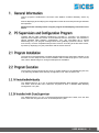
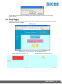
When launched, the program asks for language selection:
Once the desired language is selected, click on “OK” to confirm. The program will display the
following window:
Choose whether the program should configure the device via Ethernet or via the serial port. It
is recommended to configure the device for the first time with the serial port. Use the serial
port if the current GMT IP address is not recognized and the Ethernet network being
used does not support the UDP protocol.
To use the serial port, close the GMT dip switch 1 (SW3 bank switch 1= ON).
Device search in
pro
Open it again at the end of configuration, otherwise the Ethernet connection will not work.
Select "Serial port" and click on "Finish".
4
USER MANUAL
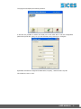
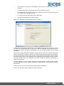
The program will display the following window:
It will then be possible to select the serial port to be used and to set the configuration
parameters (baud rate, parity, etc.) for the selected port by clicking on "Configure".
By default, the GMT is configured for 9600 baud, no parity, 1 start bit and 1 stop bit.
Once finished, click on "OK".
USER MANUAL
5
To use the Ethernet network for configuration, open the GMT dip switch 1 (SW3 bank switch
1= OFF).
g
Select “Ethernet” and click on "Next".
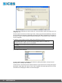
The program will display the following window:
If the current GMT IP address is unknown, leave the "I know current IP address" option
unselected. In this case, the program will search for all the GMT connected online, by means
of the UDP protocol. When the search is complete, select the desired GMT identified by its
serial number. If the network does not support UDP protocol, it is not possible to select the
previous option.
If the IP address is known, select the previous option and type this address in the relevant field
(displayed when selecting the option):
Click on "Finish" (further details in section 2.3.3).
6
USER MANUAL
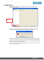
The program will now try to contact the GMT(S) online. The following window will be
displayed during the search:
s...
Once finished, the detected GMT list will be displayed in the left hand side of the window
above. If no GMT is detected, the following error message will be displayed:
If this message is displayed, there are no gateways in the network, or the program could not
use the TCP or UDP port. If the 'gateway not found' message is displayed without searching,
the program could not use the device: Check that there are no other programs running that
might use the same port (e.g., SicesSupervisor).
Each GMT is displayed with its network interface MAC address, which is unique. Click on one
of them to start the configuration.
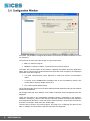
USER MANUAL
7
From here, it is possible to configure all the GMTs connected to the Ethernet network or to the
PC serial port.
The menu bar is at the top of the window. It only has two items:
Exit: To close the program
Search: To search for GMTs, as described in the previous section.
The status bar is at the bottom of the window. It displays information about the application
status, but no controls can be performed from here (there are some exceptions). The displayed
information (from left to right) is:
The used communication device (Ethernet or serial port) and the communication
status.
A counter for the ModBus/TCP messages sent in the Correct/Wrong format. This
counter will be reset by double-clicking on it.
The current system date and time.
On the left hand side, there is a list of all the GMTs detected (listed according to their network
interface MAC address).
On the right hand side of the window, once a GMT is selected, all the configuration tools are
displayed.
There are five steps for the configuration (standard version), respectively in the "System",
"Network", "Serial port", "Alarms" and "Security" tabs (the "Alarms" tab might not be displayed
if not supported by the GMT). In the web server version (version 1.00 and more recent ones),
there are 2 more tabs: “Web Vars” and “HTML Page”.
The first step is shown in the previous figure. This step is for configuring the name for the
GMT. In addition, the information acquired by the GMT are displayed:
8
USER MANUAL
Three fields that identify the manufacturer, the product, and the software release
installed.
The input status (the boxes are red if the relevant inputs are active).
The output status (the boxes are red if the relevant outputs are active). Double-click
on an output box to change its status.
The status of the two dip switches of the SW3 bank.
The status of the board non-volatile memory.
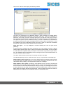
Click on the "Network" tab to display the following window:
This tab is for configuring the GMT Ethernet. An IP address is assigned to the GMT, the "subnet mask" for its network and the TCP port to be used are configured. For the first two pieces
of information, contact the network administrator. The TCP port should always be set at 502,
if possible.
GMT does not support the DHCP standard network protocol, that is the automatic assigning
of the IP addresses in a network. This is a very common protocol for Windows networks, where
there is a server (DHCP server) for this function. If the network where the GMT is to be installed
uses the DHCP protocol, an IP address must be disabled from the DHCP server (so that it
cannot be used by others) and assigned to the GMT. Contact the network administrator to
perform this operation.
It is also possible to set the network gateway IP address (router, or other) for those cases
when the GMT and the PC it should work with are in two separate networks (ask the network
administrator).
At the top of the tab, the network interface MAC address is displayed.
Click on the "Serial port" tab to display the following window:
USER MANUAL
9
This tab is for configuring the GMT serial port. Communication speed and parity type are
configured here.
If Sices boards are used to control the gen-sets, a list (by type and serial address) of devices
can be created: this list will be periodically checked by the GMT if the Ethernet connection is
not active, in order to detect possible faults and notify them on the Ethernet. Up to 16 devices
can be configured.
In addition to set the log for device polling, this parameter is used for:
- Alarm management: The alarms are managed only for DST4601 and
DST4600A device types. For the other device types, there is no polling via
Modbus and the "Alarms" tab is not available.
- Alarm reset management (according to the selected device, a different control
is sent)
- Web page: The name of the connected device is shown in the menu frame.
- Telesegnali status interrogation for DST4600A
Devices that can be selected:
In case a generic device is selected, there will be no polling via Modbus, except for those
explicitly set for reading web variables.
The first device in the table (as both address and device type) will be set to manage html pages
and alarms. More than one device can be set for polling, but those after the first one are
overlooked for managing the alarms and the html pages.
10
USER MANUAL
Click on the "Alarms" tab to display the following window:
This tab is for configuring the IP addresses where to send messages for possible alarms
detected on SICES boards connected to the GMT serial port. If the list "Configured IP
addresses" is left empty, the alarm messages will be sent in 'broadcast' mode (that is to all the
PCs connected on the network) by means of the UDP network protocol. If the network does
not support this protocol (or the 'broadcast' mode), up to four IP addresses can be added to
the above-mentioned list: the alarm messages will be sent only to these IP addresses. To add
an IP address, type it in the field above the list, then click on "Add". To remove an IP address
from the list, click on it from the list and then click on "Remove".
Keep Alive Type – It is only displayed in versions following the 1.00 one (web server
gateways).
A New Keep Alive message has been introduced in the new gateway versions: it allows
sending status variations (both when an alarm is activated and deactivated). It is also possible
to enter additional configurable data (for example: network status, key position, engine status,
etc.). The gateway can thus immediately send a message about the activation/deactivation of
an alarm or about a status change.
This option allows selecting which type of message should be managed.
The standard gateway versions, earlier than the 1.00 one, only send the old message type.
Delay between 'alarm' signals: When one of the SICES boards connected to the serial port
is in an alarm status, the GMT sends one or more network messages at regular intervals. This
value allows setting a delay (in seconds) between these two messages.
Delay between 'alive' signals: By setting a value different from 0 in this box, the GMT will
send a Keep Alive network message at regular intervals. The aim of this message is to inform
those PCs that are connected that the GMT is working correctly. This message also includes
a status indicator for the serial communication with the SICES boards, so that the PC can
detect faults also between the GMT and the boards. These messages are sent to the same IP
address than for the alarms (or in 'broadcast' mode if no IP address is set).
USER MANUAL
11
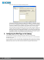
Click on the "Security" tab to display the following window:
This tab is for configuring the GMT security options. It is possible to set a password, which will
be required when connecting for Ethernet configurations. In addition, it is possible to create a
list of up to four IP addresses for Ethernet connection. If no address is set, the Ethernet
connection is available from any IP address. If the network uses the DHCP, this function
cannot be used, since not all the networked PC addresses are known or are unmodified.
Once all the steps have been performed, even if only one option has been changed, the
"Update" button will be enabled. The configuration will be sent to the GMT by clicking on it
(NB: if the program is closed, another GMT is selected, or a new search is launched without
first clicking on "Update", the configurations made will be lost). By clicking on "Cancel", it will
be possible to read the current configuration form the GMT (this is an automatic operation
performed when clicking on a GMT on the left hand side of the window).
There are two tabs from where to configure the web page: “Web Vars” and “HTML Page”.
In these two tabs, it is possible to set the data to be used by the connected device, and to download the
web page of the device.
For the configuration and use of the web page, the MdgConfig program checks that the Gateway
firmware version is 1.00 or later. The Web Vars and HTML Page tabs are only displayed if the connected
Gateway firmware version is 1.00 or later. Previous versions do not support the http connection.
12
USER MANUAL
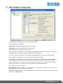
It is possible to enter variables in the configurable web page.
35 string variables are available:
ws00-ws29 30 small web variables (up to 10 characters)
wg00-wg04 5 great web variables (up to 50 characters)
The Gateway device manages the zhtml pages.
zhtml pages are html pages with some special commands that allow adding variables ('print' command),
using cycles ('for' command), conditional operators ('if' command), etc.
The 'print' command (in zhtml) in the html page allows displaying the content of the web variables.
Each variable is associated to a set of parameters for content and format.
The Gateway interrogates the device connected to the serial port requesting the configured registers,
performing the set conversions and formatting, and entering the result in the relevant web variable.
In the example above, the content of Input Register 30033 is requested to the device with Modbus 1
address. This value is converted according to a fixed table: DSt4600A Mode table.
List of parameters of web variables:
Modbus Address for the device to be interrogated – It is the Modbus address for the device to be
interrogated for the datum. By default, it is set to 1.
Activation / Register Type: It activates/deactivates the web variable and sets the register type (Input
Register or Holding Register).
USER MANUAL
13
If the value is set to 0:OFF, the variable in deactivated, and no request via Modbus will be performed
for this variable, which will then be empty.
Register to read – It sets which register needs to be read (if more registers need to be read, set the
first one).
Number of registers to read – Check how many registers are taken by the information to be used and
set the number of registers to be read in this field.
Conversion type – It sets the conversion type to be applied to the datum read in the registers.
Conversion Types
No.
1
2
3
4
5
6
7
12
13
14
15
21
22
23
24
25
26
27
Conversion Type
Description
BOOL
Boolean value (0 or 1)
US
Whole number without sign (Unsigned Short)
SS
Whole number with sign (Signed Short)
UL
Long whole number without sign (Unsigned Long)
SL
Long whole number with sign (Signed Long)
STR
String
SHEX
Hexadecimal Value
Whole number without sign (Unsigned Short) with possibility to check if
US Max Val.
not available.
Whole
number with sign (Signed Short) with possibility to check if not
SS Max Val.
available.
Long whole number without sign (Unsigned Long) with possibility to
UL Max Val.
checkwhole
if not available.
Long
number with sign (Signed Long) with possibility to check if
SL Max Val.
not
available.
Tab Engine St.
Engine status table for DST4601
Tab Key Pos
Key position table for DST4601
Tab Commut.
Commutation status table for DST4601
Tab Load Type
Load type for DST4601
Tab 4600A Mod.
Mode table for DST4600A
Tab 4600A Engine
Engine status table for DST4600A
Status
Tab 4600A Comm.
Commutation status table for DST4600A
Status
Difference between normal conversions and with maximum value control (Max Val.): The
conversion types bearing the Max Val. allow detecting the invalid values. When the relevant value
reaches the maximum positive value (US = FFFFh, SS = 7FFFh, …), some dashes will be displayed
instead of the numerical value.
Number of Divide Bits –If the whole numbers have decimals, the fractional (or decimal) bit system will
be used, that is the number of bits dedicated to the decimal information. For correct conversion, set the
number of decimal bits for the variable taken. (for more information on fractional bits, please refer to the
section about the Data transfer formats in the Modbus/TCP Gateway).
14
USER MANUAL
Insert in New Alive Status (NKA) – It is used to create the New Keep Alive message. It is therefore
only enabled if the New Keep Alive option has been activated (see option "Keep Alive Message Type"
in the "Alarms" section). A value different from zero tells the Gateway to enter the value of this register
in the New Keep Alive (NKA) message. The New Keep Alive message can contain up to the value of 5
Modbus registers, and when the value of one of the registers entered is modified, the Gateway sends
automatically the whole NKA message (without waiting for the preset time to elapse).
Multiplier (Floating point) – Not used. For future conversions, it will allow multiplying the value read
by a coefficient.
Offset (Floating point) – Not used. For future conversions, it will allow adding an offset value to the
value read.
Number of whole digits to display – To format datum display: it sets the maximum number of whole
digits to be displayed.
Number of decimal digits to display – To format datum display: it sets the maximum number of
decimal digits to be displayed.
It is possible to save / load on a file the configuration for web variables on file with .cfw extension (web
configuration). By default, there are 3 base configuration for devices: DST4600A, DST4601, and
Telesegnali.
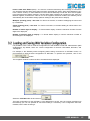
For example, if the Gateway needs configuring before being connected to a DST4601 board, it is
recommended to load the base configuration for DST4601. To perform this operation, click on the
button.
The navigation window to select the file to be loaded will be displayed:
Select the “DST4601.cfw” file and click on
.
The base configuration for the DST4601 is now displayed on the PC, but has not been transferred to
the Gateway yet. It is now possible to check and modify it, if necessary. If the configuration has been
modified, save it after renaming it.
USER MANUAL
15
Once the desired configuration has been finalised, it will be possible to transfer it to the Gateway by
clicking on the
button.
Confirmation for the operation to be performed will be required:
Press the OK button.
Wait for 2 or 3 seconds. Data will disappear shortly and will be then displayed again (they are read again
directly by the Gateway). The operation is completed.
The update loads all the board parameters together with the web variables configuration. It does not
load nor modify the web page. To load or modify the web page, please refer to the next section.
It is possible to perform the opposite operation, that is reading the configuration parameters for the web
variables from the Gateway and then save them on a .cfw file.
16
USER MANUAL
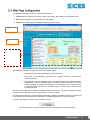
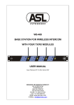
The Gateway web page consists of 3 areas (called 'frames'):
1. Header frame (containing: Sices logo, name of the device, Mac address, and software code).
2. Menu frame (containing: invokable items in web pages).
3. Data frame (containing the html page invoked by the menu item).
s
e
r
The Data frame displays the page selected from the Menu frame:
Web page of device data (depending on the board used).
Web page of the Gateway (containing the Gateway statuses: inputs/outputs,
connected device).
Web page of the alarms (displaying the alarm status and the list of activated alarms,
if applicable). In case of activated alarms, it enables the alarm reset button. The alarm
resetting sends a command to the Gateway, then forwarded to the connected device
to reset the alarms. If the alarm is not active anymore, it will be reset, otherwise it will
be displayed again.
The device web page can be modified and updated directly via Ethernet. The other web pages are fixed
and stored in the Gateway firmware, and therefore cannot be modified.
The data page for the device is automatically refreshed by updating the displayed data. The refresh rate
is contained in the web page and can therefore be modified. By default, it is set at 8 seconds.
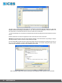
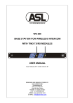
To send a web page for a device to the Gateway, click on:
The window where to select the file to be sent to the Gateway will be then displayed:
USER MANUAL
17
This file is not in a html format, but a zhtml one. Therefore, it cannot be directly created by a web page
designer software (FrontPage, Dreamweaver, etc.), but it has to be managed by using an editor. It is
also important to remember that this file must be smaller than 8,000 bytes.
To edit the web page it is necessary to be familiar with the html language and its zhtml extension for this
device.
Default .zhtml files are however supplied for all the devices that can be connected.
Attention! The html page is directly sent by double-clicking on the relevant file or by clicking on "Open"
(see figure below). Click on Cancel to stop sending the page.
It is recommended to make sure the current html page has been saved before sending the new one. If
not, or in case of doubts, use the "Receive html page" option: This allows saving the zhtml source
content for the data page currently on the Gateway on a PC file.
After sending the page, the following message will be displayed if the operation was successful:
18
USER MANUAL
The web page has been sent to the Gateway, which will then be able to send it when receiving a
browser request.
In addition to the Header frame and the Menu frame, the following web pages in the Gateway firmware
are fixed and cannot be modified:
Gateway page
Alarms page (only for DST4601 and DST4600A devices):
Alarms (with active alarms) page
Alarms (with no active alarms) page
USER MANUAL
19
The web page in the data frame can be configured, that is it is possible to transfer the zhtml code of this
page. There are some default pages that can be loaded on the gateway. Below, the list of the preconfigured pages:
DST4601 page
DST4600A page
20
USER MANUAL
Telesegnali page
UDP
User Datagram Protocol. UDP is a simple connection-less protocol for transferring datagrams. It is not
particularly reliable: It sends datagrams but provides no guarantees for delivery. The applications using
it need therefore to check the service reliability. It allows sending messages via broadcast, to all the
devices connected to the network. It can connect to a network device without knowing its IP address.
TCP
Transmission Control Protocol. Data transport protocol used in Internet. It ensures the received files are
not corrupted by transmitting data in 'segments'; the receiving system then sends its messages when
receiving these segmented data.
HTML
HyperText Markup Language. It is the hypertext/hypermedia programming language used for the
documents destined to the World Wide Web. Browsers recognize 'tags', html information, and
reorganise and display them on the user's screen.
ZHTML
HTML language extension used to add commands and variables. It adds tags with special commands
for printing variables (print), for cycles (for), and for conditional operators (if), etc.
It is edited in the board and then transformed into HTML code to be sent to the web browsers.
ModBus
Serial communication protocol designed in 1979 by Modicon to be used with its PLCs. It is now the most
widely available tool for industrial equipment and electronic device connection.
Formats:
Modbus RTU = binary coding, compact, but less readable.
Modbus ASCII = more extended coding, but more readable.
IP Address
USER MANUAL
21
Each computer or device is identified on the Internet by a numeric address of 4 groups of numbers (from
0 to 255) with a full stop as separator (for example: 188.147.6.90). Each IP address can have a
corresponding DNS address (for example: www.xyz.com).
Frame
It is an independent area in a WEB page. Frames allow spitting the BROWSER window in more
independent documents, as if they were separate windows with a size that can be defined in percentage
or in a fixed setup.
MAC
MAC address is also known as physical, Ethernet, or LAN address. It is a 48 bit code (6 byte) uniquely
assigned to each Ethernet network board worldwide.
Ethernet
It is a standard protocol for boards and cables for fast computer connection on a local network (LAN).
Originally designed in 1976 by Xerox, Intel and Digital for 10 Mbps local networks. It is described in the
IEEE 802.3 protocol for the Ethernet standard. Computers in an Ethernet network can also be of different
types or use different operating systems. It has a Bus Architecture and it is based on the CSMA/CD
(Carrier Sense Multiple Access with Collision Detection) protocol. Communication cards must be
installed on the computers or attached systems. These cards connect to the network via a coaxial cable
or a telephone twisted pair cable. The transmitted datagrams length can vary and can be up to 1,500
bytes. Technology has further developed with time, and the Ethernet communication standard is now
able to transmit up to 1,000 Mbps (fast Ethernet).
TCP Port, UDP Port
TCP and UDP protocols introduce the idea of communication port. To be exact, each TCP or UDP
datagram contains a sender port and a destination port. At the IP level, they will also contain the IP
address information of the sender and of the receiver.
For a datagram to be received, the destination port needs to be listening on the set port, otherwise the
datagram cannot be delivered. In general, an application that is used for network services needs to be
always listening for the same port, so that those who want to access it know how to do it. On the other
side, an application that wants to access a service needs to open an unused local port, and then TCP
or UDP datagrams can be sent (according to the protocol characteristics at the higher level) to the
service address and port. The application performing the service needs to know to which port to answer,
as this information is contained in the TCP and UDP datagrams.
http
(Hyper Text Transfer Protocol) - It is the fundamental protocol for the World Wide Web, to transfer on
the network the hypertext documents between the Web clients (browser) and the servers that manage
and send these documents.
Gateway
Protocol converter. It is an hardware device to connect networks that would not be compatible otherwise.
It converts data codes and transmission protocols to ensure interoperability.
DHCP
Dynamic Host Configuration Protocol. It is the protocol used to assign IP addresses to network
computers. DHCP replaces the outdated BOOTP, with which it is compatible backwards.
Browser
A browser is a program that allows Internet surfing, to be exact, browsing the World Wide Web. The
main function of a browser is to read the HTML code (and more recently, the XHTML code) and to
display it as hypertext.
DST4600A, DST4601, DST4601PX, DST4400
Electronic devices by Sices to control generator sets.
Telesegnali
Electronic device by Sices to command and control digital inputs and outputs. It can be connected to other
devices via serial port by using a ModBus protocol.
22
USER MANUAL
This document is owned by SICES s.r.l.. All rights reserved. SICES s.r.l. reserves the right to modify
this document without prior notice.
SICES has made any effort to ensure that the information herein provide are correct; in any case
SICES does not assume any liability for the use these information.
The disclosure by any means of this document to third parties is not allowed.
SSSTTTTTGHTY
1