1
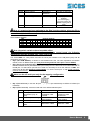
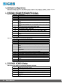
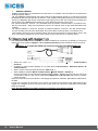
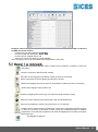
Filename: EAAM019216EN.docx Rev. 06 Date: 09/05/2013 ID Document: EAAM0192 Product: DITEL 1. General information................................................................................................. 3 2. Basic characteristics ............................................................................................... 3 3. Connections ............................................................................................................. 4 3.1 RS485 interface connections and power .............................................................. 4 3.1.1 CPU module input .......................................................................................... 4 Connection to DST4601, DST4601PX, DST4400, AC3000 without galvanic insulation ................................................................................................................... 4 3.1.3 Connection to DST4601, DST4601/PX, DST4400, AC3000 with galvanic insulation and remote input ........................................................................................ 5 3.2 CPU 16 Inputs module (ref. - fig. 1a and 1b) ........................................................ 6 3.3 8 outputs relay module (optional) (ref. - fig. 2) ...................................................... 7 3.4 DITEL Modules Interconnection (ref. - fig. 3) ........................................................ 7 4 Configurations .............................................................................................................. 8 4.1 DITEL Versions .................................................................................................... 8 4.1.1 E6102093400XX Ditel 16 Input ver. A ............................................................ 8 4.1.2 E6102094400XX Ditel 16 Input ver. B ............................................................ 8 4.2 Default Configurations ........................................................................................ 10 4.2.1 DST4601, DST4601/P, DST4601/PX 16 relays ........................................... 10 4.2.2 DST4400, AC3000 16 Relays ...................................................................... 10 ii 5. Mapper 1.xx ............................................................................................................ 11 5.1 How to map with mapper 1.xx ............................................................................ 12 5.2 Mapper 1.xx commands ..................................................................................... 13 5.3 Mapper 1.xx basic instructions ........................................................................... 14 6. List of Ditel board ModBus addresses ................................................................ 16 User’s Manual This document describes the technical, functional and operational characteristics of the DITEL board. The DITEL TELESIGNAL device, when used with SICES genset control boards, lets you expand the available digital inputs and outputs on the SICES control board with 16 digital inputs and 16 digital outputs in addition to the standard inputs and outputs of the control board. Currently, the following boards are compatible with the DITEL system: N. Ditel Outputs modules (8 outputs) 2 2 N. Additional Inputs N. Additional Outputs 1 1 N. Ditel CPU modules (16 Inputs) 1 1 16 16 16 16 2 2 4 32 32 Board N. Ditel to connect DST4601 DST4400 / AC3000 DST4601/PX Note: An RS485 com port is required to connect the DITEL boards. The available modules have the following codes: 1. E6102093400xx : DITEL CPU Module 16 Inputs Ver. A, 12 / 24VDC input (main module). 2. E6102094400xx : DITEL CPU Module 16 Inputs Ver. B, 12 / 24VDC input (main module). 3. E6102093500xx : DITEL 8 outputs relay module, system with 24VDC input. 4. E6102093501xx : DITEL 8 outputs relay module, system with 12VDC input. Up to two E61020935XXXX 8 RELAY MODULE units can be connected to each inputs module using a flat-cable with 10 conductors. Note: The 8 relay module E61020935XXXX does not require external power. The states of all the inputs and outputs managed by the DITEL are available through the RS485 serial port of the Sices control board, and the outputs can be controlled manually (on the basis of the selected operating mode). Alternatively, the DITEL lets you activate the outputs on the basis of the states received from the boards connected to the same. In this case you can configure the device using the default mapping or by uploading mapping from a PC. See the chapter MAPPING for more information. The device has 16 opto-insulated inputs which are acquired with the relevant filters. The input is acquired by earthing the corresponding pin. The DITEL can be managed by devices using the same protocol (PLC, PC); the encoding and mapping procedures are covered in this document. - - Input voltage o Base module: 7-32 VDC o 12V relay version: 9-16 VDC o 24V relay version: 18-30 VDC reverse polarity protection. max. current absorption: 220mA @ VDC=30V, Vout=10V, Zout=100 ohm max. current of relays: 5 A operating temperature: -10 + 50 °C weight cpu module: 180 g 8 relay module: 150 g User’s Manual 3 The DITEL has a RS485 communications bus which is insulated from the input/output circuits and the built-in logic. This gives the transistors high voltage immunity and eliminates problems caused by variations in the input voltages of the devices connected by the bus. This is useful in the case of difficult connections, in environments with heavy disturbances or where the equipotential connection between earth and the devices cannot be guaranteed (for example: direct connection to PC). Note: (Only E6102094400xx version): Ditel CPU 16 Inputs ver. B). On the board there is a RS232/485 Serial jack stereo interface not galvanically insulated, for a quick connection with a PC for the relais output Mapper configuration. The device can be connected directly to DST4601, DST4601/PX boards of any kind with the “Double CAN and RS485” E62020271170X or “CAN-Control motor-RS485” E6202027119XX options; this solution is suitable in the case of use in the same board, because the internal interfaces of the DST4601, DST4601/PX are not insulated; if galvanic insulation is required, one of the options providing a second RS232 serial port can be used (E6202027107XX, E6202027113XX, E6202027118XX ) with the insulated converter RS232/RS485 E61020217XXXX. The device can be connected to the DST4400 board with the E620207910200 option. The AC3000 board comes with this option. Note: (Only A version): The RS485 interface must be powered externally through pins 5 and 1 of connector J2; these are respectively the positive and negative input of the interface; the input voltage is between 10 and 32V. Note: (Only B version): The RS485 interface requires no external power. Depending on the intended use (with or without galvanic insulation) and the type of control board, the power can be supplied in various ways. Note: (Only A version): The RS485 interface can be powered with the same input voltage as the device using a screened cable with two conductors plus the screen. This solution can be used in a cabinet housing also the control board, where the power input has the same potential. Note: (Only B version): The RS485 interface requires no external power. 4 User’s Manual Note: (Only A version): The RS485 interface power input of the DITEL device is the same as that of the control device (no galvanic separation); a screened cable with 4 conductors plus the screen is required. This solution can be used for short sections, also between several boards. Note: (Only B version): The RS485 interface requires no external power. User’s Manual 5 The connections are made using removable terminals, plus 2 flat-cable connectors for the external connection to 2 x 8 relay module boards. Internally the device consists of 2 boards: CPU module board + Modular 16 inputs telesignal board. Each input has a signal LED. LEGEND 1 - dipswitchs 2 – Digital inputs 1÷16 3 - RS485 serial 4 - Supply 5 – Digital inputs 1÷16 6 – Warning lights Fig. 1a CPU 16 inputs E61020934xx ver. A LEGEND 1 - dipswitchs 2 - Digital inputs 1÷16 3 - RS485 serial 4 - Supply 5 - Digital inputs 1÷16 6 - Warning lights 7 - RS232/RS485 Serial jack Fig. 1b CPU 16 inputs E61020944xx ver. B LED COLOUR IN 1 ÷ IN 16 Red POWER ON Green REMOTE Yellow FUNCTION Indicates the corresponding input (6) is active (lit when earthed). Lit when the device is powered (6). Off = no active communication Lit fixed = modbus communication active and stable (6). Note: In normal conditions, REMOTE led (6) should be lit fixed to indicate the modbus communication is active and stable. If the modbus communication is active, but REMOTE led (6) is off, check the communication timeout isn't set to 0 (the default value is 50, which corresponds to 5 sec.). 6 User’s Manual Note: Up to two relay modules can be connected to the 16 inputs CPU main board. The max. current at each output is 1A; CAT III insulation. The relay modules are powered directly by the inputs module connection through a flat-cable with 10 conductors. Each output has a signal LED (3). The leds light when the corresponding output is active, in other words when the contact closes between COM and NO. LEGEND 1 – Digital outputs 1÷8 / 9÷16 2 - Relais contacts outputs 1÷8 / 9÷16 3 – Warning lights out Fig. 2 - Relay Outputs Board the DITEL CPU module must always be present with its 16 inputs, while the connection of one or two 8 relay modules is optional depending on the number of outputs required. As shown in the following diagram, 2 flat cables come out of the DITEL CPU module to connect 2 x 8 relay modules. Fig. 3 - Board interconnection Important: the modules must be assembled on the same DIN bar (the modules of the same group must be as close as possible to each other) User’s Manual 7 4 Note: (Only E6102093400xx Ditel 16 Inputs Ver. A). This electronic device can be configured with a bank (1) of 4 dipswitches SW 1,2 Description Modbus address 3 Outputs Configuration 4 Device connected ON See table of addresses Default mapping Control board OFF See table of addresses Mapping uploaded from PC (if a valid mapping hasn't been loaded, the default mapping will be used) PC, PLC, etc... Note: If a mapping has been uploaded to the Ditel, but the switches select the PC as the connected device (dipswitch 4 = OFF) it will not be considered. Set dipswitch 4 = control board on (device connected). Select Modbus address: Switch n. 2 OFF OFF ON ON Switch n. 1 OFF ON OFF ON Modbus address 1 2 3 4 Note: the switch variations have immediate effect. Important!: To use the mapping configured with the control board, the following dipswitches must be selected: sw3=OFF, sw4=ON. Note: (Only E6102094400xx Ditel 16 Inputs Ver. B). This electronic device can be configured with two banks (1) of 4 dipswitches and a banks (1) of 8 dipswitches. 8 User’s Manual SWN 1,2,3,4 Description Modbus address 5,6 7 ON See table of addresses Default mapping Not used Outputs Configuration 8 Control board Device connected OFF See table of addresses Mapping uploaded from PC (if a valid mapping hasn't been loaded, the default mapping will be used) PC, PLC, etc... Note: If a mapping has been uploaded to the Ditel, but the switches select the PC as the connected device (dipswitch 8 = OFF) it will not be considered. Set dipswitch 8 = ON control board (device connected). Select Modbus address: SWN id SW4 SW3 SW2 SW1 1 2 X 3 4 X X X 5 6 X X X MODBUS ADDRESS 7 8 9 10 11 X X X X X X X X X X 12 X X X 13 X X 14 X X X 15 X X X 16 X X X X Note: the switch variations have immediate effect. Important!: To use the mapping configured with the control board, the following dipswitches must be selected: sw7 = OFF, sw8 = ON. The switch SWP is a 4-way switch and sets the serial port available on the JP (stereo jack) and J2 connectors (ref. Fig 1b): Dip1 (120 OHM ON/OFF): it allows to connect/disconnect the 120 ohm impedance termination resistor on the JP RS485 serial port (only if necessary and onlt if this port is set as RS485) Dip 2 (Serial port enable/disable): it enables/disables the serial port on the JP stereo jack. With the RS485 insulated version (E6102094400xx) the serial port on the J2 connector is shared with that on the JP jack. To select which port has to be used it is necessary to act on the switch 2 of SWP. The serial ports J2 and JP cannot be used together. To use the serial port on J2, the JP connector must be disconnected. Note: use the JP serial port only for the mapping configuration Dip 3 (RS232/RS485): it sets the JP (stereo jack) serial port alternatively as RS232 or RS485 (not insulated) Dip 4 (9600/19200 Bd): it sets the baud rate of the JP and J2 serial ports SWP 1 2 3 4 Description Line impedence termination (only JP port) JP serial port enabling JP serial port selection JP and J2 serials Baud Rate ON RS485 line impedance 120Ω inserted JP RS232/RS485 serial disabled JP set as RS232 OFF RS485 line impedance 120Ω not inserted JP RS232/RS485 serial enabled JP set as RS485 Baud rate= 19200 Baud rate = 9600 User’s Manual 9 When the mapping is active, the DITEL device checks if the memory contains a valid mapping downloaded using mapper. The default mapping is used if no other mapping has been saved: Table valid if the DITEL is connected to DST4601 or DST4601PX RELAYS 1 2 3 4 5 6 7 8 9 10 11 12 13 14 15 16 DESCRIPTION Powered by network (KR closed) Powered by generator (KG closed) Engine started Alarms (A.41 and A.42) and prealarms (W.43 and W.44) oil pressure Water temperature alarms (A.33 and A.34) and prealarms (W.31 and W.32) Emergency stop (A.48), automatic stop button (A.07), no stop (A.21) alarms Overload (A.15 and A.06), short circuit (A.16) and energy inversion (A.11) alarms Min. or max. generator voltage alarms (A.01, A.02) Min. or max. generator frequency alarms (A.03, A.04) Overspeed alarms (A.17, A.18, A.19) No start (A.22), nominal operating conditions not reached (A.08) alarms Belt snapped alarm (A.05), battery anomaly prealarms (W.37, W.38) Fuel alarms and prealarms (A.25, A.26, W.27, W.28, W.29, W.30) Alarm 1 (immediate, A.46), Alarm 2 (delayed, A.47) or auxiliary prealarm (W.10) Cumulative malfunction (or alarms and prealarms) Selector OFF/RESET or PROG or MAN Table valid if the DITEL is connected to DST4601/P RELAYS 1 2 3 4 5 6 7 8 9 10 11 12 13 14 15 16 DESCRIPTION Mains on Generator ready Engine started Alarms (A.41 and A.42) and prealarms (W.43 and W.44) oil pressure Water temperature alarms (A.33 and A.34) and prealarms (W.31 and W.32) Emergency stop (A.48), automatic stop button (A.07), no stop (A.21) alarms Overload (A.15 and A.06), short circuit (A.16) and energy inversion (A.11) alarms Min. or max. generator voltage alarms (A.01, A.02) Min. or max. generator frequency alarms (A.03, A.04) Overspeed alarms (A.17, A.18, A.19) No start (A.22), nominal operating conditions not reached (A.08) alarms Belt snapped alarm (A.05), battery anomaly prealarms (W.37, W.38) Fuel alarms and prealarms (A.25, A.26, W.27, W.28, W.29, W.30) Alarm 1 (immediate, A.46), Alarm 2 (delayed, A.47) or auxiliary prealarm (W.10) Cumulative malfunction (or alarms and prealarms) Selector OFF/RESET or PROG or MAN Table valid if the DITEL is connected to DST4400 / AC3000 RELAYS 1 2 3 4 5 6 10 User’s Manual DESCRIPTION Powered by network (KR closed) Powered by generator (KG closed) Engine started Alarms (A041 and A042) and prealarms (W043 and W044) oil pressure Alarms (A033 and A034) and prealarms (W031 and W032) water temperature Emergency stop (A048), automatic stop button (A007), no stop (A021) alarms 7 8 9 10 11 12 13 14 15 16 Overload (A015 and A006), short circuit (A016) and energy inversion (A011) alarms Min. or max. generator voltage alarms (A001, A002) Min. or max. generator frequency alarms (A003, A004) Overspeed alarms (A017, A018, A019) No start (A022), nominal operating conditions not reached (A008) alarms Belt snapped alarm (A005), battery anomaly prealarms (W037, W038) Fuel alarms and prealarms (A025, A026, W027, W028, W029, W030) Signal from inputs: J204-3 (W101 / A101 : Generic anomaly from “Oil Pressure” input used as digital), J204-4 (W102 / A102 : Generic anomaly from “W. Temp. Veglia/VDO” input used as digital), J204-2 (W103 / A103 : Generic anomaly from “Fuel Level” input used as digital) Cumulative malfunction (or alarms and prealarms) Selector OFF/RESET or PROG or MAN In the case in which the definitions of the relay board outputs are incompatible with the type of plant, you can use the mapping configuration to configure the outputs to suit your needs, in accordance with the events in the "Mapper 1.xx" software table. If configured properly, the control boards send the state via modbus continuously (several times a second) writing 8 modbus 16 bit registers and keeping the same updated. This means a total of 128 status bits, of which each bit indicates a condition of the board, engine or system (example: position of the lockable selector, low fuel alarm, low oil pressure, belt snapped, etc….). The mapping indicates whether and which outputs to activate for the corresponding state, for each of the possible states transmitted. If the belt snaps for example, one, none, or several outputs may be activated on the basis of the mapping. Therefore, the mapping is represented by a table with all the possible states (128) and the outputs that can be controlled (16 for the DITEL board). The rows show 128 states (the interpretation of which changes on the basis of the board selected) and the columns show the 16 outputs. Therefore, we have a total mapping of 128x16=2048 bits, in other words 256 bytes. A mapping occupies 256 bytes of memory. When mapping is active, the DITEL board instantaneously verifies the states received from the boards, and scans the mapping to activate the corresponding outputs. The outputs that aren't mapped can be controlled directly, in other words if there is an output with no reference in the table to a board state, it can be controlled by writing the modbus address 40001. The direct writing of outputs already mapped has no effect. IMPULSE OUTPUTS The impulse outputs allow automatic deactivation in the case of direct control. Every output can be set as an impulse output. The impulse duration can be set (for all outputs). User’s Manual 11 MODBUS TIMEOUT Modbus communication is considered ‘lost’ when there is no modbus communication for the set timeout (Holding Register 40501). N.B.: the REMOTE led lights when the board receives a valid modbus request. If no request is received the REMOTE led turns off after the set timeout. If the modbus interrogation frequency is lower than the timeout, the REMOTE led will turn off and then light again (in this case we recommend increasing the timeout time). If the REMOTE led remains off, check that the timeout isn't set to zero. The outputs enabled in ‘Timeout 1’ are activated when the modbus communication is considered ‘lost’, after the set timeout. When the transmission returns, the outputs return to the initial deactivated rest condition. The outputs enabled in ‘Timeout 0’ function as outputs enabled in ‘Timeout 1’ but with inverted logic: they are normally active and are deactivated when the modbus communication is considered ‘lost’. In the mapper, the first row is for impulse outputs, the second and third for Timeout outputs. Also in this case, if an output is mapped on one or more outputs it cannot function as an impulse output. The configuration requires the connection to a PC via RS232 (JP connector) or RS485 (J2 connector) and the use of the program Mapper 1.06 or following releases (previous releases cannot be used). Note: to connect the RS232 JP serial port use the cable E090000000142 Select the correct serial port on the PC (Menu Communication Select Communication resource) Impostare la porta seriale utilizzata su PC (Dal Menù Comunicazione Seleziona Risorsa di comunicazione). Set the correct communicatoin parameters: 9600, N, 8, 1 Set the Modbus address (Menu Communication Serial address : default=1) Connect the DITEL to a PC using the RS485 (with the RS485 – RS232 converter you can connect to a serial port of the PC) and use the programme Mapper Ver.1.06 and later (the previous versions cannot be used). Select the board to connect the DITEL in the Mapper Programme: DST4601, DST4601PX, DST4400 or AC3000. A map of the outputs will be shown on the screen: the columns correspond to the digital outputs (the mapper can configure up to 32, but only the first 16 are used). The 128 rows correspond to the possible states of the board. note: The description of the states changes on the basis of the board selected. X indicates the OUT is activated for the state indicated. 12 User’s Manual Example: if we want output 12 to be activated when the lockable selector of DST4601 is switched to MAN, proceed as follows: check the type of board selected is DST4601 find the row with the description “Mode: MAN” find the column of digital output n.12 click on the column row enter box (an X appears) After configuring, save to file and transmit the configuration to the board. Open the connection with the DITEL module (send continuous requests to check the connection). Close the connection with the DITEL module. Send the current mapping to the DITEL module (it must be connected) DITEL memorises the new mapping permanently in eeprom. Detects the mapping saved in the memory of the DITEL module (it must be connected). Cleans the mapping to save another one Reads the mapping saved to file (you can select the folder and file to read) Save the current mapping to file (Select disk, path and destination file) Send current mapping to printer (connected to PC or in a network) Create a file for external eeprom programmer. Used by the Telesignal board with eeprom on base, the memory of the DITEL module cannot be programmed with an external programmer. In this way the programmer can save the mapping on more than one eeprom at the same time. Exit Mapper programme User’s Manual 13 If the mapping has a white background it can be modified by clicking in the boxes. If the mapping background is grey this means the grid is blocked and no changes can be made. To make changes to the mapping loaded, go to the Commands menu and decheck “Deactivate modifications”. Follow the instructions below to load a mapping in the DITEL board: 1. Connect the DITEL board to a PC. A PC doesn't normally have RS485 ports, so you should use a RS232-RS485 converter. Connect the RS232 of the converter to the PC, and the RS485 side to the DITEL module. 2. Run the Mapper programme on the PC (install the programme if it isn't on the system). Check the version is 1.06 or later (The version is shown on the title bar of the window). 3. Select a communication resource: in the Communication menu, click on “Select communication resource”. 4. 5. 14 Select the COM port the DITEL module is connected to. Click on Configure and Verify the communication parameters (9600, N, 8 ,1) : User’s Manual 6. Check that the address of the peripheral device is set correctly. Note: (Only DItel Ver.A) In most cases the address is 1 (dipswitches 1, 2 of the DITEL module must be OFF). Dipswitches 3 and 4 do not affect the configuration with the mapper, the mapping can be read and written regardless of the state of these four 2 switches. Note: (Only DItel Ver.A) In most cases the address is 1 (dipswitches 1, 2, 3, 4 of the DITEL module must be OFF). Note: Dipswitches 5, 6, 7 and 8 do not affect the configuration with the mapper, the mapping can be read and written regardless of the state of these four 4 switches. To display and/or modify the address, select “Peripheral device address” in the Communication menu. 7. Click on the icon Connect 8. 9. 9. Check the DITEL module is communicating with the PC. N. correct answers / N. errors Upload the selected mapping from file. Click on 10. Select the path and file to upload, then press OK. 11. Execute to send the mapping to the DITEL module. 12. If the operation was successful, the following will be displayed 13. After mapping, you must turn the unit off and on again. User’s Manual 15 The Ditel manages the transmission of up to approximately 47 modbus registers. Requests that exceeds the transmission buffer generate an error message (exception). In reception, the commands that exceed the dimension of the buffer will not be processed. Input Register From 30001 To 30001 Description Digital INPUTS (1..16) 30002 30002 DIP SWITCH (bit 0-3: 4 current low bits, bit 8-11: 4 high bits with pwr on) Note Displays the current state of the 16 inputs connected to the 16 Inputs Module. Read switch on CPU DITEL board Holding Register 16 From 40001 To 40001 Description Digital OUTPUTS (1-16) 40002 40002 N.U. 40003 40010 STATES DST4601 / DST4601PX 40101 40356 Mapping 40357 40358 Impulse outputs map 40359 40359 Impulse duration 40501 40501 Modbus connection timeout 40502 40502 Map of outputs in case of timeout (positive logic) 40503 40503 Map of outputs in case of timeout (negative logic) User’s Manual Note Reads and writes 16 digital Out. requires additional outputs board. (n.b. : the outputs can be timed, in other words to power down automatically, check the timers for output impulses) N.B. : The old Telesignal used output values from 17 to 32. The DITEL board can manage max. 16 outputs, so this register is no longer used. Contains the states of the connected board. The connected device (DST4601, 4601PX) constantly sends the value of this register. In this way the DITEL board can set the state of the outputs on the basis of the system state, using the loaded mapping. N.B. : the mapping is only used if dipswitch 4 on the DITEL board = OFF Indicates which outputs will automatically turn off when activated. (only active on direct out commands, or with mapping but on outputs that are not mapped). Indicates the duration of the impulse for all the impulse outputs with a base of 100 ms (1=100ms, 2= 200ms, 5= 500 ms, …) The time after which the Modbus communication is considered lost. This time is set in tenths of a second. (ex. 10=1 sec, 30 = 3 sec, 50 = 5 sec …). Default: timeout = 30 (3 seconds). Indicates which outputs automatically turn on when the modbus communication is inactive for the set timeout. When communication returns, the active outputs return to the logic state ‘0’. Default: no output configured. Indicates which outputs automatically turn off when the modbus communication is inactive for the set timeout. When communication returns, the active outputs return to the logic state ‘1’. Default: no output configured. This document is owned by SICES s.r.l.. All rights reserved. SICES s.r.l. reserves the right to modify this document without prior notice. SICES has made any effort to ensure that the information herein provide are correct; in any case SICES does not assume any liability for the use these information. The disclosure by any means of this document to third parties is not allowed. SSSTTTTTGHTY 1