1
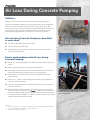
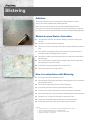
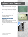
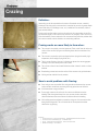
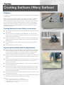
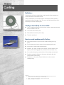
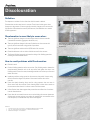
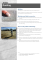
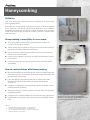
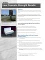
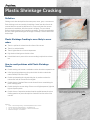
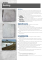
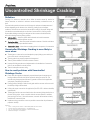
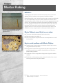
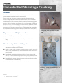
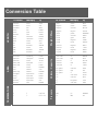
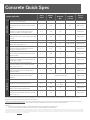
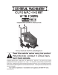
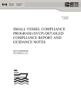
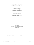
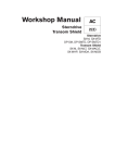
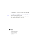
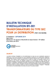
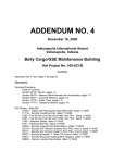
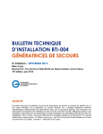
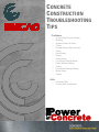
CONCRETE CONSTRUCTION TROUBLESHOOTING TIPS Problems o o o o o o o o o o o o o o o Air Loss During Concrete Pumping Blistering Bugholes (Surface Air Voids) Crazing Crusting Surfaces (Wavy Surfaces) Curling Discolouration Dusting Honeycombing Low Concrete Strength Results Plastic Shrinkage Cracking Scaling Uncontrolled Shrinkage Cracking Mortar Flaking Popouts Aids o o Conversion Table Concrete Quick Specifications Problem: Air Loss During Concrete Pumping Definition: Changes in the air content of the concrete due to concrete pumping operations. Concrete air entrainment requirements are typically based upon concrete sampled and tested from concrete supplied at the end of the chute of the concrete truck. When concrete is placed via a concrete pump and the acceptance samples are obtained at the end of the pump, there are a number of additional factors that the contractor must consider since pumping operations can reduce the air content of the concrete. Air Loss during Concrete Pumping is more likely to occur when: The concrete undergoes significant vertical drops The concrete has a high initial slump Concrete pumping on a residential radiant floor heating project The pumping pressure is increased and there is a sudden pressure drop as the concrete exits the pump hose How to avoid problems with Air Loss during Concrete Pumping: Operate the concrete pumping boom in an upward or horizontal position as much as possible Reduce vertical concrete drops to the shortest possible length Insert multiple 90° elbows into the line to create a residual amount of concrete in the line and to minimize the long straight drop out of the pumping line Utilize a gate or flow restricting device at the end of the pump line to provide resistance to flow Run the last 3 – 5 metres of the pumping hose horizontally along the subgrade or formwork to avoid vertical drops Using cable, loop the end section of the rubber hose into a circle to prevent direct free fall out of the hose Elevate the plastic air content above the specification limits at the concrete truck location to account for the actual air loss (Caution – Inspection of the air content at both the truck and the pumping location becomes extremely critical whenever there is a change in the boom configuration – higher air contents in the final concrete have a negative impact on compressive strength) References: 1 Concrete in Practice #21 – Loss of Air Content in Pumped Concrete – National Ready Mixed Concrete Association 2 ACI 116 – Cement and Concrete Terminology – American Concrete Institute 3 RMCAO Concrete Digest – Second Edition Concrete pumping on a commercial project using a flow restriction device to provide resistance to flow and to prevent direct free fall Problem: Blistering Definition: The irregular raising of a thin layer at the surface of placed mortar or concrete during or soon after completion of the finishing operation. Blisters form just under the surface of the concrete when either bleed water or entrapped air is prevented from escaping the concrete. This typically occurs when the top surface of the concrete has been sealed prematurely during the finishing operations. Blisters are more likely to form when: Blistering concrete surface The subgrade is cooler than the concrete resulting in non-uniform setting of the concrete Insufficient or excessive vibration is employed The concrete surface is prematurely sealed due to improper finishing procedures or tools Site conditions are resulting in rapid surface evaporation causing the finisher to mistakenly assume the bleeding period is complete Entrained air is added to non air-entrained concrete or when the air entrainment is abnormally high The concrete element is extremely thick resulting in longer times for bleed water and entrapped air to rise to the surface A dry shake is prematurely applied to the concrete surface The concrete is placed over a vapour barrier How to avoid problems with Blistering: Cross-section through a concrete blister Utilize proper concrete consolidation practices Utilize the proper finishing tools and keep the troweling blades as flat as possible to avoid sealing the surface Place concrete during periods of lower surface evaporation Avoid placing concrete on cold sub-grades whenever possible Avoid the use of chemical retarders since they will only intensify the problem Keep trowel blades flat as long as possible to avoid sealing the surface prematurely Consider the use of chemical accelerators to reduce the set time Properly heat the building and/or subgrade prior to concrete placement Avoid placing concrete on top of vapour barriers whenever possible References: 1 Concrete in Practice #13 – Concrete Blisters – National Ready Mixed Concrete Association 2 Concrete Construction Troubleshooting Tips – The Aberdeen Group 3 ACI 116 – Cement and Concrete Terminology – American Concrete Institute 4 RMCAO Concrete Digest – Second Edition Problem: Bugholes (Surface Air Voids) Definition: Small regular or irregular cavities, usually not exceeding 15 mm in diameter, resulting from the entrapment of air bubbles in the surface of formed concrete during placement and consolidation. Bugholes appear as small void on the outside of formed concrete surfaces. These defects are typically due to the presence of small air pockets that were not removed during concrete consolidation operations or by the incomplete application of the form release agent to formwork resulting in concrete adhesion during the form removal process. Bugholes are more likely to form when: Bugholes on a concrete surface created with a form liner The concrete is not adequately consolidated to remove all entrapped air Internal concrete vibrator insertions are not sufficiently overlapped or well spaced Form release agents are not used or the forms are removed before the concrete has gained sufficient strength to resist the form removal pressures Concrete mixtures are very stiff or sticky How to avoid problems with Bugholes: Uniformly consolidate the concrete ensuring that the vibrator insertion pattern is uniform and well spaced Reduce the height of each concrete placement lift to make air removal easer Bugholes on a plywood formed surface Move the vibrator as close to the formwork as possible Properly apply the form release agent and only remove the forms once the concrete has gained sufficient strength to resist any suction forces Consider the use of specialty concrete products like self consolidating concrete (SCC) References: 1 Concrete Construction Troubleshooting Tips – The Aberdeen Group 2 ACI 116 – Cement and Concrete Terminology – American Concrete Institute 3 RMCAO Concrete Digest – Second Edition Self Consolidating Concrete (SCC) significantly reduces bugholes and can be used in architectural concrete applications Problem: Crazing Definition: Intersecting cracks that extend below the surface of hardened concrete; caused by shrinkage of the drying surface concrete that is restrained by concrete at greater depths where either little or no shrinkage occurs; vary in width from fine and barely visible to open and well-defined. Crazing cracks are fine random cracks on the surface of the concrete that do not affect the structural integrity of the concrete, but which are very unsightly. These cracks rarely affect the durability or wear resistance of the concrete and are particularly evident when the concrete contains calcium chloride as an accelerating admixture. Crazing cracks are more likely to form when: Crazing on a residential garage floor slab Crazing on exterior flatwork The concrete is not properly cured and protected. These cracks form due to the top surface of the concrete drying out and shrinking faster than the remainder of the concrete The concrete is exposed to rapid or prolonged surface drying (low humidity, high temperature, direct sunlight, drying winds, etc.) There is excess floating or the use of a jitterbug to depress the coarse aggregate resulting in too much cement paste at the surface The concrete surface is hand trowel finished and when it doesn’t contain a surface hardener Broadcasting cement back onto the surface of the concrete to dry up bleed water Utilizing calcium chloride in hot dry weather How to avoid problems with Crazing: Start curing as soon as possible. Wet curing procedures that ensure the concrete surface remains continuously wet during the curing period are most effective Avoid intermittent curing procedures Do not apply cement to the surface of the concrete to eliminate excessive bleeding. Order the required slump from your concrete producer and utilize chemical admixtures like water reducers to eliminate excessive bleeding Utilize initial protection methods to prevent the drying out of the concrete surface during the finishing period. This can include the use of evaporation retardant chemicals or fog spraying References: 1 Concrete in Practice #3 – Crazing Concrete Surfaces – National Ready Mixed Concrete Association 2 Concrete Construction Troubleshooting Tips – The Aberdeen Group 3 ACI 116 – Cement and Concrete Terminology – American Concrete Institute 4 RMCAO Concrete Digest – Second Edition Problem: Crusting Surfaces (Wavy Surface) Definition: A moulded layer of plain or reinforced concrete with a non-uniform surface due to differential concrete setting. Wavy concrete surfaces or concrete crusting occurs when the top surface of the concrete begins to set while the underlying concrete is still in a plastic state. Surface crusting is caused by differential stiffening or setting of the concrete. A thin portion of the top surface of the concrete begins to set while the underlying concrete is still plastic. Surface finishing operations must then be completed over a jelly like concrete base resulting in differential movement of the slab surface during finishing operations, which results in wavy and/or cracked concrete surfaces. Crusting Surfaces are more likely to occur when: There are significant temperature and/or moisture differences between the bottom and top of the slab Concrete is placed on a cold subgrade. The cold subgrade acts as a heat sink while portable heaters are being used on the top surface of the slab to maintain the necessary placement and curing temperatures Environmental conditions are resulting in rapid surface moisture loss. High winds, direct sunlight and low relative humidity conditions result in concrete surface stiffening during the drying process Concrete mix designs with low bleeding characteristics are more prone to concrete crusting Chemical retarders are used in the concrete Walk behind power trowel How to avoid problems with Crusting Surfaces: Minimize temperature differentials between the concrete surface and the subgrade or formwork. During winter months the subgrade must be properly heated well before the concrete placement and during summer months work should be scheduled to avoid placing concrete during periods when the air temperature is rising significantly Utilize proper initial curing protection strategies such as “fog spraying” and “evaporation retardant” compound to minimize moisture differentials between the bottom and top of the slab Consider the use of finishing tools that open the surface of the concrete and don’t result in surface sealing. Delay floating as long as possible since this is the operation that creates most of the bumps Ensure that all floating and troweling equipment is used in a flat position to minimize the chance of sealing the surface Consider the use of chemical admixtures to accelerate the setting rate of the concrete. Do not use chemical retarders to delay the setting time of the concrete since this will only intensify the concrete crusting problem. Minimize any variations between loads of concrete and avoid unloading delays Delay power troweling as long as possible to minimize the waviness that will be created during the finishing operations Use the pans on power trowels to break open the concrete surface immediately after the bleed water period ends to promote uniform concrete stiffening References: 1 Concrete Construction Troubleshooting Tips – The Aberdeen Group 2 ACI 116 – Cement and Concrete Troubleshooting – American Concrete Institute 3 Troubleshooting Crusted Concrete – Bruce Suprenant – Concrete Construction 4 RMCAO Concrete Digest – Second Edition Ride on power trowel An example of a wavy concrete surface Problem: Curling Definition: A deviation of a slab from its original shape, usually caused by either temperature or moisture differentials or both within the slab. Curling is the distortion of a concrete slab into a curved shape by either upwards or downwards bending of the edges of slab. This occurs when the top and bottom of the slab change size (shrink) at differing rates. Curling is more likely to occur when: Illustration of curling of a concrete slab on grade There is a significant difference in either moisture content or temperature between the top and bottom of the slab The concrete slab is relatively thin When the distance between joints is large The slab is unreinforced How to avoid problems with Curling: Example of different levels of concrete curling based upon two different mix designs Utilize the best possible curing system and consider extending the curing period Use the lowest practical water slump and avoid retempering with water Avoid the use of vapour barriers beneath the slab Implement mix design principals that minimize concrete shrinkage (the largest possible coarse aggregate size, minimize the cement content, etc.) Use a smaller joint spacing to reduce the size of the resulting concrete panels Consider increasing the thickness of the concrete slab and/or utilize slab reinforcement to reduce curling Consider the use of specialty chemical admixtures to reduce concrete shrinkage/curling References: 1 Concrete in Practice #19 – Curling of Concrete Slabs – National Ready Mixed Concrete Association 2 Concrete Construction Troubleshooting Tips – The Aberdeen Group 3 ACI 116 – Cement and Concrete Terminology – American Concrete Institute 4 RMCAO Concrete Digest – Second Edition Problem: Discolouration Definition: The departure or variation of colour from that which is normal or desired. Discolouration can take many forms in concrete. These forms include: gross colour changes over large areas of concrete typically caused by changes to the concrete mix; light patches of discolouration caused by efflorescence; dark blemishes or a mottled surface appearance. Discolouration is more likely to occur when: There are significant changes to the mix design related to the raw materials (cementitious materials, aggregates, admixtures, etc.) There are significant changes in the rate of hydration over the concrete slab typically due to inconsistent curing periods or operations There are significant variations in the W/CM ratio of the concrete Chemical admixtures such as calcium chloride are used in the concrete The flatwork finisher improperly estimates the timing of the finishing operations resulting in a hard-troweled surface Discolouring of a residential driveway due to the use of calcium chloride (accelerator) in only one of the two loads How to avoid problems with Discolouration: Chloride is used Conduct finishing operations at the correct time. Early finishing tends to elevate the water/cementing materials ratio at the top surface and lighten the colour. Late finishing tends to lower the water/cementing materials ratio at the top surface and darken the colour Implement a uniform curing system for the necessary time period. Uneven curing directly affects the degree of hydration of the cement and the colour of the concrete Ensure that plastic sheeting, when used for curing purposes, does not come in direct contact with the concrete. Plastic sheeting tends to leave colour streaks on the concrete surface where it is in direct contact with the concrete Utilize effective form release agents that prevent the non-uniform loss of moisture from the formed surface Ensure that the raw material sources are not varied during the concrete placement. Architectural concrete projects may require the stockpiling of raw materials at the concrete plant (at a considerable cost) for the entire project References: 1 Concrete in Practice #23 – Discoloration – National Ready Mixed Concrete Association 2 ACI 116 – Cement and Concrete Terminology – American Concrete Institute 3 RMCAO Concrete Digest – Second Edition The proper application of a curing compound Problem: Dusting Definition: The development of a powdered material at the surface of hardened concrete. Dusting is the formation of loose powder caused by the disintegration of the top surface of the concrete due to an extremely weak surface. Dusting is more likely to occur when: An example of a dusting concrete surface Any finishing operation is performed while there is bleed water on the top surface of the slab The concrete is not properly cured resulting in an extremely weak surface The concrete is exposed to carbon dioxide while still in its plastic state The concrete surface is not protected during the initial concrete placement (wind, rain, snow, freezing) How to avoid problems with Dusting: Do not perform any finishing operations on the concrete while bleed water is still present on the surface. If the finishing operations work the bleed water back into the concrete they elevate the w/cm ratio of the surface layer significantly and dramatically reduce the surface layers strength Initiate proper curing practices as soon as possible and cure the concrete for the specified period Avoid placing concrete on vapour barriers since they can extend the bleeding period into the initial set/finishing period Ensure that all heating devices and construction equipment is vented outside the work area to avoid carbon dioxide build-up above the slab while the concrete is still plastic Adding water to the concrete surface to aid the finishing operations will significantly weaken the surface and increase the problems with dusting Proper concrete curing practices significantly reduce dusting problems References: 1 Concrete in Practice #1 – Dusting Concrete Surfaces – National Ready Mixed Concrete Association 2 Concrete Construction Troubleshooting Tips – The Aberdeen Group 3 ACI 116 – Cement and Concrete Terminology – American Concrete Institute 4 RMCAO Concrete Digest – Second Edition Problem: Honeycombing Definition: Voids left in concrete due to failure of the mortar to effectively fill the spaces among coarse aggregate particles. Honeycombing of concrete typically occurs when the concrete is allowed to segregate due to obstructions in the flow of concrete during placement or due to inadequate consolidation techniques after the concrete is placed. Depending on the extent and location of the honeycombing, this defect can be either a cosmetic or structural defect in the final product. Honeycombing is more likely to occur when: The concrete element contains reinforcing steel that limits the ability of the concrete to flow through the formwork There is limited access or locations for placing concrete in the formwork resulting in large spacings between concrete placement locations High concentrations of reinforcing steel prevent the insertion of internal concrete vibrators in key structural locations Large size coarse aggregate is used in the mix design and reinforcement is present in the formwork Concrete mix designs are not properly proportioned for the necessary flowability and workability Honeycombing in a residential shear wall Honeycombing in a concrete column How to avoid problems with Honeycombing: Work with the engineer and the reinforcing steel contactor to minimize restrictions due to reinforcing steel. This can include the resizing of the rebar and avoiding rebar lap splices in key structural areas Ensure that optimum concrete vibration practices are followed. This includes decreasing the height of the lifts, reducing the distance between vibrator insertions, etc. Designing or re-engineering the concrete element to allow for acceptable concrete placement methods and locations Allowing the contractor to select the appropriate concrete slump for the placement technique being utilized Designing the mix to optimize flowability and to minimize the coarse aggregate size Considering the use of specialty concrete products like self consolidating concrete (SCC) References: 1 Placing and Vibrating Poured Concrete Walls – Concrete Construction 2 Concrete Construction Troubleshooting Tips – The Aberdeen Group 3 ACI 116 – Cement and Concrete Terminology – American Concrete Institute 4 RMCAO Concrete Digest – Second Edition Self Consolidating Concrete (SCC) can be used to successfully address challenging concrete placements. However, please keep in mind that the quality of the formwork is also critical since the formwork surface will be perfectly mirrored in the concrete element Problem: Low Concrete Strength Results Definition: When the test results from the concrete cylinders or beams used as the basis of material acceptance fail to meet the strength requirements of CSA A23.1 Clause 4.4.6.6.1. CSA A23.1 recognizes the fact that when concrete is proportioned to meet the requirements of the standard, low strength results will occur about once or twice per every 100 tests. Acceptable concrete complies with the requirements of CSA A23.1 Clause 4.4.6.6.1 when: Concrete cylinders used for concrete acceptance purposes must be stored in a temperature controlled environment - not left to bake in the sun An example of proper field curing methods includes the use of a temperature controlled curing box The averages of all sets of three consecutive strength tests for that class of concrete equal or exceed the specified strength No individual test result is more than 3.5 MPa below the specified strength Low Concrete Strength Results are more likely to occur when: The concrete testing is performed by unqualified persons CSA A23.1/.2 concrete testing requirements are not followed When test specimens are improperly handled, cured and tested The jobsite addition of excessive amount of water is allowed The wrong concrete is ordered for the concrete placement How to avoid problems with Low Concrete Strength Results: Ensure that all concrete field testing is only performed by CCIL or ACI Certified concrete technicians Ensure that all concrete testing is performed in strict accordance with CSA A23.1/.2 Verify that the proper facilities exist for the site storage of test samples prior to the start of concrete placement. Every jobsite should include a curing box which maintains the samples at a temperature between 15°C and 25°C Review the concrete delivery ticket for every load of concrete and compare that to specification requirements for the element being constructed Utilize the “Pre-Pour Meeting Form” to clearly designate the person with authority for jobsite water addition and specifically define the conditions when water addition will be allowed References: 1 CIP #9 – Low Concrete Cylinder Strength – National Ready Mixed Concrete Association 2 Concrete Construction Troubleshooting Tips – The Aberdeen Group 3 ACI 116 – Cement and Concrete Terminology – American Concrete Institute 4 RMCAO Concrete Digest – Second Edition Problem: Plastic Shrinkage Cracking Definition: Shrinkage cracks that develop before the cement paste, mortar, grout, or concrete sets. Plastic shrinkage cracks are caused by the rapid loss of water from the surface of the concrete before the concrete has had time to set. These cracks form after concrete placement and consolidation, while the concrete is still plastic. They are relatively shallow in depth and tend to form in parallel to one another. The cracks are unappealing but rarely cause significant damage to the strength or durability of the floor due to their shallow depth. Plastic Shrinkage Cracking is more likely to occur when: There is a rapid loss of moisture from the surface of the concrete There is low relative humidity There is high ambient air or concrete temperatures High winds are blowing across the slab surface Limited bleed water is present in the concrete resulting in rapid surface moisture loss Plastic shrinkage cracks on exterior flatwork How to avoid problems with Plastic Shrinkage Cracks: Consider erecting wind screens or sunshades to reduce the surface evaporation rate Utilize fog spraying equipment on the up-wind side of the slab to maintain the relative humidity of the slab at 100% Consider pre-dampening the sub-grade during hot dry weather to reduce the moisture loss from the concrete into the subgrade Consider the use of synthetic fibres to resist the tensile forces created during the plastic shrinkage period Consider placing the concrete during off-hours to avoid high temperature, high wind, high sun exposure periods Consider the use of evaporation retardant chemicals applied between the various finishing operations to prevent the rapid loss of moisture from the surface of the concrete References: 1 CIP #5 – Plastic Shrinkage Cracking – National Ready Mixed Concrete Association 2 Concrete Construction Troubleshooting Tips – The Aberdeen Group 3 ACI 116 – Cement and Concrete Terminology – American Concrete Institute 4 RMCAO Concrete Digest – Second Edition CSA A23.1 defines severe drying conditions as when 2 surface moisture evaporation exceeds 1.0 kg(m .hr) Problem: Scaling Definition: Local flaking or peeling away of the near-surface portion of hardened concrete or mortar. Light scaling of a concrete sidewalk Scaling begins as small localized patches of the concrete surface that debonds from the concrete typically due to freeze-thaw exposure. With time these localized patches can expand and merge together to produce large scaled areas. The various levels of scaling are defined by the American Concrete Institute (ACI) as: Light Scaling – Scaling of the concrete that does not expose the coarse aggregate Medium Scaling – Scaling of the concrete that involves loss of surface mortar to 5 to 10 mm in depth and exposure of the coarse aggregate Severe Scaling – Scaling that involves loss of surface mortar to 5 to 10 mm in depth with some loss of mortar surrounding the aggregate particles of 10 to 20 mm in depth Very Severe Scaling – Scaling that involves loss of coarse aggregate particles as well as mortar generally to a depth greater than 20 mm Scaling is more likely to occur when: The concrete contains insufficient air entrainment or is non-air entrained The concrete has not been properly cured The concrete is exposed to deicing chemicals of any type Improper concrete has been utilized for exterior applications. The Ontario Building Code and CSA A23.1 both specify a minimum of 32 MPa, 0.45 W/CM, air entrained concrete for exterior applications exposed to freeze-thaw cycles and deicing chemicals When finishing operations are completed while the bleed water is still on the concrete surface The concrete is placed during adverse weather conditions (extreme heat, extreme cold, during the rain, etc.) How to avoid problems with Scaling: Medium scaling of a concrete sidewalk Proper concrete curing practices significantly reduce instances of concrete scaling Order and place the proper concrete for the application (32 MPa, 0.45 W/CM, air entrained concrete) Properly cure the concrete. Exterior concrete requires a minimum of 7 days curing in order to ensure that the concrete surface develops the necessary durability properties to resist scaling Avoid the use of deicing chemicals on the concrete surface. Deicing chemicals should not be used at all during the first winter and only sparingly after that Avoid the use of deicing chemicals that chemically attack concrete Allow at least 30 days of air drying of the concrete slab after the curing period before exposing the slab to freeze-thaw cycles. The elevated moisture content of new concrete initially reduces the effectiveness of the air entrainment Consider the proper use of concrete sealers to reduce the absorption of moisture and chlorides into the concrete Utilize wet curing methods during hot weather and severe drying conditions and fog spray the concrete surface between finishing operations References: 1 CIP #5 – Plastic Shrinkage Cracking – National Ready Mixed Concrete Association 2 Concrete Construction Troubleshooting Tips – The Aberdeen Group 3 ACI 116 – Cement and Concrete Terminology – American Concrete Institute 4 RMCAO Concrete Digest – Second Edition 5 Ontario Building Code – 2006, Ontario Ministry of Municipal Affairs & Housing – Housing Development & Buildings Branch Problem: Uncontrolled Shrinkage Cracking Definition: Cracking of a structure or member due to failure in tension caused by external or internal restraints as reduction in moisture content develops, carbonation occurs, or both. Concrete both expands and contracts with changes in moisture and temperature and deflects depending on the element size, reinforcing, loading force and support conditions. All these factors can lead to uncontrolled cracking if the proper design and joint details are not addressed prior to the time of construction. In order to prevent uncontrolled shrinkage cracking, the designer and the contractor should effectively utilize the following concrete jointing systems: Isolation Joints – Joints that permit both horizontal and vertical movement between the slab and the adjacent concrete Contraction Joints – Joints that permit horizontal movement of the slab and induce controlled cracking at pre-selected locations Construction Joints – Joints that are stopping places in the process of construction Design and construction of a proper isolation joint Uncontrolled Shrinkage Cracking is more likely to occur when: The designer or contractor has not developed a proper jointing system and layout prior to the start of concrete placement The sub-grade is not properly prepared and compacted There is jobsite addition of excessive amounts of water Improper finishing procedures are implemented or the installation of contraction joints is not completed in a timely fashion There is inadequate concrete curing Design and construction of proper contraction joints How to avoid problems with Uncontrolled Shrinkage Cracks: Ensure that the subgrade is adequately prepared based upon the exposure and loading conditions that the slab will be exposed to during its service life. This includes using the appropriate thickness of granular sub-base for the application and properly compacting the sub-base Ensuring positive drainage of both the sub-grade and the concrete surface to avoid the build-up of high moisture levels Utilizing the proper concrete for the application (See CSA A23.1 minimum durability requirements) The designer and the contractor should review the concrete jointing details prior to the start of the project. Items to consider include concrete thickness, maximum joint spacing (4.5m max.), fibre reinforcement, structural reinforcement and early installation of contraction joints Implement curing procedures as soon as possible to ensure that the performance properties develop References: 1 CIP #4 – Cracking Concrete Surfaces – National Ready Mixed Concrete Association 2 Concrete Construction Troubleshooting Tips – The Aberdeen Group 3 ACI 116 – Cement and Concrete Terminology – American Concrete Institute 4 RMCAO Concrete Digest – Second Edition Design and construction of proper construction joints Problem: Mortar Flaking Definition: The dislodging of small sections of concrete mortar directly over top of the coarse aggregate particles in exterior concrete exposed to freeze/thaw conditions. Mortar flaking typically occurs in exterior flatwork that was not properly cured during the first 7 days. Mortar flaking is typically very shallow in depth and consists of distinct delamination (flakes) that occur directly over top of the coarse aggregate particles in the concrete. This is typically due to the fact that the concrete mortar directly over top of the coarse aggregate was allowed to dry out and was not properly cured. Any excess bleed water that is present in the concrete is forced to travel around the coarse aggregate particles, as it rises to the surface and the mortar directly above fails to develop the necessary strength required to achieve proper durability and bond. Mortar a concrete sidewalk – note that the Mortarflaking flakingonon a concrete sidewalk – Note that aggregate is sound and only theonly mortar the aggregate is sound and the above mortarthe above aggregate has failed the aggregate has failed Mortar Flaking is more likely to occur when: The concrete is placed during periods of rapid surface drying When the concrete is not cured at all When curing compound is applied too late after concrete placement or not until the following day How to avoid problems with Mortar Flaking: Ensure the proper curing procedures are followed at all times! Proper concrete curing should eliminate this problem During periods of rapid surface drying consider using initial curing procedures like evaporation retardants or placing plastic sheeting over the concrete surface between finishing operations Consider the use of wet curing methods during severe drying and hot weather conditions Consider the use of fog spraying systems to protect the surface of the concrete from drying out until wet curing can be initiated Cross-section a mortar flakeflake – note that only Cross-sectionthrough through a mortar – note that the above above the coarse has failedhas onlymortar the mortar the aggregate coarse aggregate failed References: 1 ACI 116 – Cement and Concrete Terminology – American Concrete Institute 2 RMCAO Concrete Digest – Second Edition Problem: Uncontrolled Shrinkage Cracking Definition: Conical fractures of the concrete surface caused by the expansion of ice inside porous coarse aggregates located just below the concrete surface. Popouts result when soft porous aggregates, found both in limestone and gravel sources, undergo freeze/thaw conditions in a saturated state. While air entrainment provides protection for the cement paste from the expansive forces generated during winter freeze/thaw cycles, it does not provide any protection for the coarse aggregate particles. If the local aggregate sources contain even a small percentage of soft, porous particles (like chert), the coarse aggregate can absorb significant quantities of moisture and fractures during freeze/thaw cycles. The resulting expansion fractures both the aggregate and the surrounding concrete. Popouts are distinguished from mortar flaking by the presence of fractured aggregate in the popout (as shown in the sample photo). Popouts are more likely to form when: Popout surface damage caused by the fracture of a soft aggregate particle during winter freeze/thaw cycles The local aggregate sources contain soft, porous material The concrete is in a fully saturated condition The concrete hasn’t achieved its ultimate durability potential due to inadequate curing How to avoid problems with Popouts: Consider the use of alternative aggregate sources. This may require the import of aggregates at a significant additional expense Consider changes to the aggregate processing process to further reduce the quantity of soft porous material (the complete elimination of all soft material is not normally possible) Ensure that the overall design minimizes the build-up of excess moisture in the concrete. This can be achieved through proper surface grading and draining of the surrounding subgrade Ensure that proper concrete curing and protection practices are followed to achieve the highest possible concrete durability Consider the use of sealers to limit the inflow moisture into the concrete A cross-sectional view of a concrete core taken from a popout area – note the large chert particle in this limestone aggregate source that is responsible for the popout References: 1 ACI 116 – Cement and Concrete Terminology – American Concrete Institute 2 RMCAO Concrete Digest – Second Edition Conversion Table By To Obtain inches inches feet feet yards miles millimetres centimetres metres metres kilometres metres kilometres kilometres 25.40 2.54 30.45 0.3048 0.9144 1.6093 0.03937 0.3937 39.37 3.281 3280.90 1.094 1094.60 0.61 square inches centimetres2 0.1550 0.00108 10.764 0.1111 0.3987 0.000247 2.471 0.003861 6.4529 0.0929 0.8361 2.59 0.00404 5/9 (°F-32) 9/5 °C +32 square feet square feet square yards square yards acres acres square miles centimetres2 metres2 metres2 kilometres2 kilometres2 C ° F ° 2 centimetres metres2 square feet metres2 metres2 hectares hectares square inches square feet square yards square miles acres ° F C ° Weight / Mass millimetres centimetres centimetres metres metres kilometres inches inches inches feet feet yards yards miles Volume / Capacity Multiply Pressure TEMPERATURE AREA LENGTH To Obtain Multiply By grams ounces 28.35 kilograms pounds 0.4536 kilograms short tons 907.185 kilograms long tons 1016.05 tonnes pounds 0.0004536 tonnes short tons 0.9072 ounces grams 0.035 pounds kilograms 2.2046 pounds tonnes 2204.59 short tons kilograms 0.0011 short tons tonnes 1.1023 long tons kilograms 0.0010 long tons tonnes 0.9842 cubic inches cm3 0.06104 cubic inches litres 61.02 3 cubic feet m 35.3143 cubic feet litres 0.3532 cubicyards 3 m 1.3079 Imp. gallons cubic feet 6.236 Imp. gallons litres 0.22 Imp. gallons 3 m 219.97 cm3 cubic inches 16.387 cubic feet 28.32 m Imp. gallons 3.154 m3 cubic yards 0.764 MPa psi psi MPa 0.006895 145 3 cm 3 Concrete Quick Spec Residential Industrial / Commercial / Institutional Agricultural Concrete Application Reinforced beams, slabs and columns over manure pits exposed to severe manure gases Reinforced walls in exterior manure tanks, silos, and feed bunkers exposed to severe to moderate manure gases Structurally reinforced interior walls, beams, slabs and columns in a continuously submerged condition exposed to moderate to severe manure gases Non-structurally reinforced slabs on grade exposed moderate manure gases or liquids without freeze-thaw exposure Class of Concrete A–1 Maximum W/CM Minimum 28d Strength (MPa) Chloride Ion Permeability at 56 days Reference Standard 35 1500 Coulombs CSA A23.1-09 N/A CSA A23.1-09 0.40 A–2 0.45 32 A–3 0.50 30 CSA A23.1-09 4–4 0.55 25 CSA A23.1-09 High Performance Concrete C – XL 0.40 50 within 56 days 1000 Coulombs CSA A23.1-09 Structurally reinforced concrete exposed to chlorides (Bridge decks, parking decks, etc.) Non-structurally reinforced concrete exposed to chlorides and freezing and thawing (Garage floors, pavements, sidewalks, curbs, etc.) Continuously submerged concrete exposed to chlorides but not freezing and thawing (Underwater portions of marine structures) C–1 0.40 35 1,500 Coulombs CSA A23.1-09 C–2 0.45 32 CSA A23.1-09 C–3 0.50 30 CSA A23.1-09 C–4 0.55 25 CSA A23.1-09 F–1 0.50 30 CSA A23.1-09 F–2 0.55 25 CSA A23.1-09 Specified by the Designer CSA A23.1-09 Non-structurally reinforced concrete exposed to chlorides but not freezing and thawing (Underground parking slabs on grade) Concrete exposed to freezing and thawing in a saturated condition but not to chlorides (Pool decks, patios, tennis courts, etc.) Concrete in an unsaturated condition exposed to freezing and thawing but not to chlorides (Exterior walls and columns) Concrete not exposed to chlorides or freezing and thawing (Footings and interior slabs, walls and columns) N Footings for walls, columns and chimneys R–1 0.70 (3 – 6%) CSA A23.1-09 Foundations, walls, grade beams, piers, etc. R–2 0.70 15 (4 – 7% air) CSA A23.1-09 Interior slabs on ground not exposed to freeze-thaw without a vapour barrier beneath the slab R–3 0.65 20 CSA A23.1-09 Garage floors and all concrete exposed to freezing and thawing and deicing chemicals (Driveways, sidewalks, patios, steps, etc.) C–2 0.45 32 CSA A23.1-09 Owner may order concrete to Performance Specifications (concrete supplier is responsible for concrete as delivered) or Prescriptive Specifications (Owner is responsible for concrete as delivered). Detailed Concrete Mix Proportions shall not be disclosed by the concrete supplier. CONCRETE PLANT CERTIFICATION SPECIFICATION: “The concrete supplier shall submit to the concrete purchaser a currently valid Certificate of Ready Mixed Concrete Production Facilities or a currently valid Certificate of Mobile Mix Concrete Production Facilities as issued by the Ready Mixed Concrete Association of Ontario to the plant being used.” References: 1 Ontario Building Code - 2006, Ontario Ministry of Municipal Affairs and Housing - Housing Development and Buildings Branch 2 CSA A23.1-09 Concrete Materials and Methods of Concrete Construction - Canadian Standards Association International With the permission of Canadian Standards Association, material is reproduced from CSA Standard A23.1-09/A23.2-09, Concrete Materials and Methods of Concrete Construction/Methods of Test and Standard Practices for Concrete which is copyrighted by Canadian Standards Association, 5060 Spectrum Way, Suite 100, Mississauga, ON L5W 5N6. While use of this material has been authorized, CSA shall not be responsible for the manner in which the information is presented, nor for any interpretations thereof. A23.1/23.2-09 is intended to be used in its entirety. Caution should be exercised in extracting individual clauses or tables and using them in project specifications, since taking them out of context can change their meaning. For more information on CSA or to purchase standards, please visit their website at www.shopcsa.ca or call 1-800-463-6727. THIS INFORMATION TO BE USED AS A GUIDELINE ONLY. FOR MORE DETAILED INFORMATION OR SPECIFICATIONS, PLEASE CONSULT REFERENCES. Prepared by: Ready Mixed Concrete Association of Ontario 365 Brunel Road, Unit #3 Mississauga, Ontario L4Z 1Z5 T: 905.507.1122 F: 905.890.8122 [email protected] RMCAO.org © 2013 RMCAO. All rights reserved. 02/13