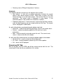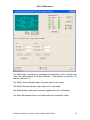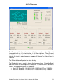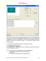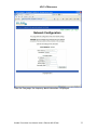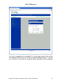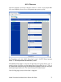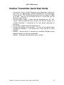
1
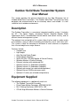
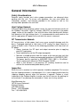
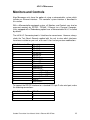
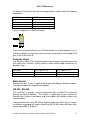
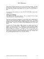
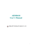
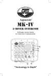
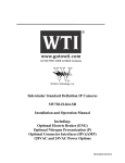
Page: Title
USER MANUAL
OUTDOOR TRANSMITTER
16715 Hymus Boulevard, Kirkland, Quebec, H9H 5M8, CANADA
Tel. 1-514-694-8666
FAX 1-514-694-3615
www.alga.ca
Revision
Date
ECN Change Summary
A
9-Jul-12
Initial release
B
24-Jul-12
Added GUI info
C
4-Oct-12
Added redundancy info
D
2-Feb-13
Added LO select and input divider redundancy
E
3-Mar-14
Added 1:2 and refreshed screenshots
Date: 3-Mar-14
Rev: E
Approval
KL
KL
KL
KL
KL
Alga Microwave
User Manual
Solid State Transmitter
Systems
With Serial & Ethernet
Microcontroller
COMPANY CONFIDENTIAL
This document is the property of ALGA Microwave and may be neither used, copied, nor reproduced
outside of the company. Nor may its contents be communicated outside of the company, except with the
written permission of
ALGA Microwave
ALGA Microwave
Table of Contents
Table of Contents ..............................................................................................2
Outdoor Solid State Transmitter System User Manual......................................4
Description.....................................................................................................4
Equipment Supplied.......................................................................................4
General Information .......................................................................................5
Safety Considerations ................................................................................5
High Voltage Hazards ................................................................................5
RF Transmission Hazards..........................................................................5
Inspection...................................................................................................5
Return of Equipment ..................................................................................6
Ports and Interfaces.......................................................................................7
Prime Power Connection............................................................................7
IF Input .......................................................................................................8
RF Output...................................................................................................8
M & C Connector........................................................................................8
Redundancy Port .......................................................................................9
Airflow ........................................................................................................9
Monitors and Controls..................................................................................10
Summary Alarm .......................................................................................11
Mute Control.............................................................................................11
RS-232 / RS-485......................................................................................11
LEDs and LO Select.................................................................................12
Monitor and Control Software ......................................................................13
Installation Instructions.............................................................................13
Monitors and Alarms ................................................................................13
Controls....................................................................................................15
Remaining GUI Tabs................................................................................15
1:1 Redundancy Functions.......................................................................20
1:2 Redundancy Functions.......................................................................24
Ethernet Interface ........................................................................................26
Network Configuration..............................................................................26
Web Interface...........................................................................................26
Outdoor Transmitter Quick Start Guide .......................................................36
General Maintenance ..................................................................................37
Basic Cleanliness.....................................................................................37
Internal Fuse ............................................................................................37
Fan Replacement.....................................................................................37
Theory of Operation.....................................................................................38
AC / DC Converter ...................................................................................38
DC / DC Converter ...................................................................................38
Cooling System ........................................................................................38
Block Upconverter Module .......................................................................38
Booster Amplifier......................................................................................38
Microcontroller..........................................................................................39
Outdoor Transmitter User Manual Serial & Ethernet MC RE.doc
2
ALGA Microwave
Attenuator Module....................................................................................39
10 MHz Module ........................................................................................39
Dual Transfer Switch ................................................................................39
Appendix A ..................................................................................................40
Installation Notes for 1:1 Redundant System ...........................................40
Appendix B ..................................................................................................43
Installation Notes for 1:2 Redundant System ...........................................43
Outdoor Transmitter User Manual Serial & Ethernet MC RE.doc
3
ALGA Microwave
Outdoor Solid State Transmitter System
User Manual
This section provides the general information for the Alga Microwave line of
Outdoor Solid State Transmitters. The Outdoor Solid State Transmitter has been
designed and manufactured to be an extremely robust and reliable. It is well
suited for harsh outdoor environments.
Description
The Outdoor Transmitter is a one-piece integrated amplifier system. It includes
the AC / DC Power Supply, microwave Booster Amplifier Module, Block
Upconverter (BUC), microcontroller based monitor and control circuitry, and an
efficient thermal management system.
The reduced size and weight of this system allow it to be used in a wide variety
of installations; many of which historically precluded the use of solid state units.
This system is ideal for mounting on the boom of small antennas or anywhere
that size and weight are a major concern.
Features include:
• Compact size
• Light weight
• Auto-Sensing Power Supply
• Output Power Detection
• Serial (RS-232 / RS-485) Monitor & Control Circuitry
• Windows Monitor & Control Software
• Ethernet interface with web based GUI
• Optional Internal 1:1 Redundant Capability
• Optional Internal 1:2 Redundant Capability
• Optional gain control (on selected configurations)
• Optional internal 10 MHz reference signal
• Optional LO select (on selected configurations)
Equipment Supplied
The following equipment is supplied with each unit:
• The Outdoor Transmitter Assembly
• Prime Power Mating Connector, MS3106E16-10S
• M & C Mating Connector, MS3116F14-19S
• CD with Alga Microwave Monitor & Control Software
Outdoor Transmitter User Manual Serial & Ethernet MC RE.doc
4
ALGA Microwave
General Information
Safety Considerations
Potential safety hazards exist unless proper precautions are observed when
working with this unit. To ensure safe operation, the user must follow the
information, cautions, and warnings provided in this manual as well as the
warning labels placed on the unit itself.
High Voltage Hazards
Only qualified service personnel should service the internal electronic circuitry of
the Outdoor Transmitter. High DC voltages (400 VDC) are present in the power
supply section of the amplifier. Care must be taken when working with devices
that operate at this high voltage levels. It is recommended to never work on the
unit or supply prime AC power to the unit while the cover is removed.
RF Transmission Hazards
RF transmissions at high power levels may cause eyesight damage and skin
burns. Prolonged exposure to high levels of RF energy has been linked to a
variety of health issues. Please use the following precautions with high levels of
RF power.
• Always terminate the RF input and output connector prior to applying
prime AC input power.
• Never look directly into the RF output waveguide.
• Maintain a suitable distance from the source of the transmission such that
the power density is below recommended guidelines in ANSI/IEEE C95.1.
The power density specified in ANSI/IEEE C95.1-1992 is 10 mW/cm².
These requirements adhere to OSHA Standard 1910.97.
• When a safe distance is not practical, RF shielding should be used to
achieve the recommended power density levels.
Inspection
When the unit is received, an initial inspection should be completed. First ensure
that the shipping container is not damaged. If it is, have a representative from the
shipping company present when the container is opened. Perform a visual
inspection of the Outdoor Amplifier to make sure that all items on the packing list
are enclosed. If any damage has occurred or if items are missing, contact:
Alga Microwave Inc.
16715 Hymus Boulevard
Kirkland, Quebec
H9H 5M8 Canada
Phone: 1-514-694-8666
Fax: 1-514-694-3615
Outdoor Transmitter User Manual Serial & Ethernet MC RE.doc
5
ALGA Microwave
Return of Equipment
When returning items back to Alga Microwave for replacement or repair, please
prepare the following information:
•
•
A written description of the problem encountered.
The part number and serial number of the unit in question.
Once this information is ready, contact Alga Microwave for a Return Material
Authorization (RMA) number and shipping instructions.
An RMA number may also be requested by e-mail at [email protected].
Outdoor Transmitter User Manual Serial & Ethernet MC RE.doc
6
ALGA Microwave
Ports and Interfaces
Prime Power Connection
The Prime Power Connector is the point where the unit receives input power.
Two different configurations are possible: AC input or DC input (please review
the unit’s accompanying Bench Test Record to determine which type of input is
used).
The AC input can operate over a range of 90 - 270 VAC, at 47 - 63 Hz. This
connector is a 3 pin circular connector, MS3102R16-10P. The mating connector,
MS3106E16-10S, is supplied.
DC input models may use the same AC input connector described above, or a 2
pin connector MS3102R16-11P. The mating connector MS3106F16-11S is
supplied.
Units with higher output power levels should be powered only from a 180 - 270
VAC source. This will keep AC line currents to a safe operating level. In some
cases, the unit may only be specified to operate at higher input voltage levels –
please consult the accompanying Bench Test Record for this information.
Whether AC or DC input, when wiring up the mating connector, carefully
follow the pin descriptions noted in the accompanying Bench Test Record.
Incorrect connections can seriously damage the unit. Please contact the
factory if there are any questions regarding these input connections.
Here is a diagram of the wire insertion view of the mating connector supplied with
the unit. Note that this is can also be used when looking at the connector on the
unit. Here is a sketch of the 3 pin connector:
A
C
B
And here is a sketch of the 2 pin connector:
Outdoor Transmitter User Manual Serial & Ethernet MC RE.doc
7
ALGA Microwave
A
B
IF Input
The IF Input connector is a type N female connector (type F female is an option).
The input frequency is in the L Band. Nominal RF input levels are approximately
-40 dBm depending on the output power level and the system gain of the unit.
The maximum input level should be limited to +10 dBm to avoid damaging
the unit.
The input connector must also receive a 10 MHz reference signal, which is used
to frequency lock the internal Block Upconverter. Absence of this signal will
place the unit into a muted condition and a Lock Monitor alarm will be present.
The nominal input level of the 10 MHz reference signal is 0 dBm (+/- 5 dB).
Units are also available with an internal 10 MHz reference, which do not require
an external source. Consult the test sheet that came with your unit to verify this.
RF Output
The RF Output is brought out through coaxial or waveguide in the Outdoor
Transmitters. The Ku Band Transmitters have a WR-75 Grooved Flange while
the C Band Transmitters have CPR style grooved flange (CPR-137G). An
isolator is provided at the output flange with a termination capable of handling full
reflected output power.
The Transmitter’s output is taken from the coaxial or waveguide RF Out port.
Caution should be observed here to make sure that the antenna or a suitable
termination is connected to this port before operating the Transmitter. The
Transmitter is protected against full reflection but dangerous levels of microwave
energy can be present at this port.
Never look directly into the RF output waveguide.
M & C Connector
The Monitor and Control (M & C) connector is the primary input for controlling the
Transmitter and monitoring fault conditions. It is a 19 pin circular connector,
MS3112E14-19P. It requires a mating connector, MS3116F14-19S, which is
supplied with the unit. See the next section for a more detailed explanation of
the M & C functions.
Outdoor Transmitter User Manual Serial & Ethernet MC RE.doc
8
ALGA Microwave
Here is a diagram of the wire insertion view of the mating connector supplied with
the unit. Note that this is can also be used when looking at the connector on the
unit.
M
L
K
A
N
U
J
P
V
T
H
B
C
R
E
S
G
D
F
Redundancy Port
Present on Redundant configured units only. The interface connector is used to
connect between two Transmitters and a waveguide / coaxial dual switch when
used in a 1:1 or 1:2 redundant system. The connector is MS3112E14-15P. It
requires a mating connector MS3116F14-15S, which is usually built into a
provided mating cable assembly (Daisy Chain Redundancy Cable).
A Redundant configured unit may be operated in stand-alone mode, and
behaves in a similar way to a normal Microcontroller equipped unit. If this is
done, it is important to cover the Redundancy Port to protect it from the external
environment, since there are live voltages present on this interface. Never
connect anything accept for the supplied Daisy Chain Redundancy Cable to this
interface port.
Airflow
The air intake and exhaust are both located on the bottom side of the
Transmitter. The intake is brought through a fan while the exhaust is along the
rows of heat-sink fins. A minimum clearance of 12 inches (305 mm) should be
maintained between the air intake of the Outdoor Transmitter and exhaust during
operation. This will ensure that there is no forced re-circulation of airflow from
exhaust to intake.
Lower output power units are not equipped with a fan, but the same clearance
stated above must be kept around the unit for proper operation.
Outdoor Transmitter User Manual Serial & Ethernet MC RE.doc
9
ALGA Microwave
Monitors and Controls
Alga Microwave units have the option of using a microcontroller system which
includes an Ethernet interface. This controller system interface is described in
this section.
With a Microcontroller equipped system, all Monitors and Controls can also be
accessed remotely by RS-232 / RS-485 / Ethernet to a Personal Computer.
Units equipped with a Redundancy option have a Microcontroller M & C installed
by default.
The full M & C Connector pinout is listed here for convenience. However, always
check the Test Bench Record supplied with the unit to view which interfaces
have been installed on your unit, or to see if it has had any custom modifications.
M & C Connector Pin
A
B
C
D
E
F
G
H
J
K
L
M
N
P
R
S
T
Description
RS-485 Tx+
RS-485 TxRS-485 Rx+
RS-485 RxRS-232 Tx
RS-232 Rx
RS-232 GND
Ethernet Tx+
Ethernet TxEthernet Rx+
Ethernet RxEthernet GND
Summary Alarm NO
Summary Alarm COM
Summary Alarm NC
Mute In
Mute Return
To connect the RS-232 interface to a standard PC 9 pin D-sub serial port, make
the following connections:
M & C Connector Pin
E
F
G
DB-9 Pin
2
3
5
Outdoor Transmitter User Manual Serial & Ethernet MC RE.doc
10
ALGA Microwave
To connect the Ethernet interface to a network hub or switch, make the following
connections:
M & C Connector Pin
H
J
K
L
RJ45 Pin
1
2
3
6
Here is a diagram of an RJ45 connector:
If you wish to connect directly to a PC Ethernet port for testing purposes, use a
crossover adapter, or make your own crossover connection by exchanging RJ45
pins 1 with 3 and 2 with 6.
Summary Alarm
The Summary Alarm “ORs” together various internal alarms and summarizes the
unit state on this interface. A relay contact is used, and this table summarizes its
possible states.
Unit state
No alarm (all good)
Alarm
M & C pins P - N
Closed
Open
M & C pins P - R
Open
Closed
Mute Control
Shorting the pins S and T together will disable the Booster Amplifier module.
Leaving them open will keep the unit enabled.
RS-232 / RS-485
This serial link is normally used to communicate with a remote PC running the
Monitor and Control Software. This enables a simple way to view / control the
Monitors and Controls listed above, and also enables the functions listed in the
sections below.
Communication links using RS-232 are typically good up to 30 ft. (9 m) in length.
Installations exceeding this length should use the RS-485, which will allow serial
control up to 4000 ft. (1200 m).
Outdoor Transmitter User Manual Serial & Ethernet MC RE.doc
11
ALGA Microwave
Note that the RS-485 connection uses a 4 wire, half duplex interface. So there
will only be one signal on the transmit or receive lines at a time. Accordingly, it is
only necessary to connect using two pins (ex. Tx+ and Tx-) at the unit M & C
port.
Use only one serial interface at a time (RS-232 OR RS-485), and not both
simultaneously.
LEDs and LO Select
Units come with an LED status indicator. This is a bi-color LED that simply
shows green for OK, and red for alarm/mute.
Some units may come with an optional LO select function, and is recognized by a
status LED and a select button hidden underneath a sealing screw. This function
changes the Local Oscillator frequency, enabling operation in your choice of two
different bands. Consult the Test Bench Record supplied with the unit for more
details.
To access the LO select button, simply unscrew the sealing screw from its
location. Be careful not to lose it. Removing the screw will expose a toggle
button inside the unit chassis. Use a small pick to reach inside and press the
button to toggle the LO frequency. The yellow LO status LED will change state
between off and on each time the button is pressed. As an example, you may be
able to toggle a Ku band unit between regular band (output 14.0 - 14.5 GHz, LED
off), and extended band (output 13.75 - 14.5 GHz, LED on).
Outdoor Transmitter User Manual Serial & Ethernet MC RE.doc
12
ALGA Microwave
Monitor and Control Software
The Monitor and Control Software is provided on CD for units equipped with an
onboard Microcontroller system. A Windows based PC uses this software to
remotely monitor and control the transmitter through its serial port.
Installation Instructions
System Requirements:
• PC running Windows 2000 or XP, it is expected to work with Vista and 7
or higher (32 bit only)
• Display resolution of 1024 x 768 or greater
• Free serial port (RS-232 or RS-485)
Compatibility under Windows Vista and 7 has not been tested, but is expected to
work.
To install the software, copy the folder named GUI from the CD to any location
on the target PC. The folder contains 2 files named BUC-Alga-GUI.exe and
BUC-Alga-GUI.ini. Double click on the .exe file to run the GUI software.
When running the software for the first time, ensure that the correct Com Port is
selected for your serial port by clicking on the “Set Serial Port” button at the
bottom left corner.
Monitors and Alarms
Here is a typical screenshot of a system running in 1:2 redundancy configuration.
The GUI display is similar but simplified for 1:1 redundancy and standalone
configurations. For example, standalone configurations only show the status of
the single connected unit.
Outdoor Transmitter User Manual Serial & Ethernet MC RE.doc
13
ALGA Microwave
Most GUI elements are present on the SSPA tab as shown. The interface is split
into three sections labeled PA_A, PA_B, and PA_C.
For standalone
configurations, we are only interested in unit A, while 1:1 redundant
configurations will only show units A and B.
The following system monitors are present on the GUI interface, near the bottom
left corner, and are continuously updated:
• Hot spot temperature
• Output power
As well, various alarms are monitored and summarized by the rectangular LED
icons, indicating in green for no problem, and in red for alarm. These include:
• Overall On Line status
• Over temperature
• PLL out of lock alarm
• Output over power alarm
Outdoor Transmitter User Manual Serial & Ethernet MC RE.doc
14
ALGA Microwave
•
Summary alarm (ORing of the previous 3 alarms)
Controls
The following controls are present in the top part of the section:
• Gain control. In units with an internal attenuator installed, this control
allows a gain control range of 20 dB. Either enter a value in the New
Value entry box or use the slider control. Click on Set Gain to issue the
command. The current value is displayed in a box above. If the
attenuator option is not installed, this control has no effect.
• Frequency adjustment. If more accuracy is desired for the Power monitor,
enter the input frequency you are using and click on Set Freq. The current
value is displayed in a box above.
As well, further buttons are placed along the bottom right side:
• Reset Alm - used to clear latching type alarms such as over power alarm.
• Refresh - used to immediately update the GUI with fresh status
information.
• Mute - used to manually mute and unmute the unit. The current mute
status is shown to the left of this button.
As well, three GUI related controls run along the bottom edge of the window:
• Set Serial Port - used to select the desired Com port.
• Dis Timer - used to temporarily freeze any GUI screen updates.
• Exit - closes the GUI program.
Remaining GUI Tabs
Most of the time, only the SSPA tab will be used to interact with the unit. The
remaining GUI tabs are discussed briefly in this section.
Outdoor Transmitter User Manual Serial & Ethernet MC RE.doc
15
ALGA Microwave
The Switch tab is used only for redundancy configurations, and is used to show
status and switch position of the dual switch(es). Two switches are used for 1:2,
and one switch for 1:1.
The Switch Comm indicator shows the alarm status of the switch.
The Switch Position indicator shows which unit is connected.
The Switch buttons allow you to manually toggle which unit is connected.
The Reset Alarm button clears any latched alarm for the specific switch.
Outdoor Transmitter User Manual Serial & Ethernet MC RE.doc
16
ALGA Microwave
The Alarms tab gives a more detailed breakdown of alarm types. Note that some
of these will not apply for particular units.
Firmware version information is also displayed. The information on the Alarms
tab is primarily for advanced troubleshooting in consultation with the factory.
Outdoor Transmitter User Manual Serial & Ethernet MC RE.doc
17
ALGA Microwave
The Frequency tab shows information on the frequency of operation. If the unit
is equipped with an LO select function, it will show up here. The LO select
function allows choice between two different bands of operation. Note that
typically the input to output frequency mapping will change if a different band is
selected.
The Refresh button will update the status display.
The Band select area is used to change the frequency band. Select the Band,
and then click on Set to change the LO frequency. At the time of this document’s
release, these operating bands are supported:
• Band 1: IF Band: 950-1450 MHz, 14.00-14.50 GHz, LO Freq: 13.05 GHz.
• Band 2: IF Band: 950-1700 MHz, 13.75-14.50 GHz, LO Freq: 12.80 GHz
Outdoor Transmitter User Manual Serial & Ethernet MC RE.doc
18
ALGA Microwave
The Config tab is used to set internal addresses. For a standalone type unit, this
is generally set to 0x0A, and will never need to be changed.
In a redundant setup, the addresses are selected automatically by external cable
setup. Still, it may be desirable in certain circumstances to change the default
address. Please consult with the factory if you believe this may apply to your
situation.
Outdoor Transmitter User Manual Serial & Ethernet MC RE.doc
19
ALGA Microwave
The COM Mon tab shows detailed information on the raw information being
passed on the serial port. The window normally shows a stream of information
scrolling past as the unit is being polled. Use the Dis Timer button to freeze the
updates and focus on a particular message. This may only be used by Factory
troubleshooting.
A serial protocol description document is available upon request.
1:1 Redundancy Functions
In this section, the 1:1 redundancy system is described, along with GUI elements
related to redundancy control.
The 1:1 redundant system is composed of the following elements:
• Two redundant ready BUC units (unit A and unit B)
• Switch Driver
• Dual Switch, or input divider with waveguide switch
Outdoor Transmitter User Manual Serial & Ethernet MC RE.doc
20
ALGA Microwave
•
•
•
Input coaxial cabling
Output waveguides
Daisy Chain Redundancy Cable
Please review Appendix A for details on the setup of the redundant system.
Once the units are physically setup in their correct orientation, the port
connections from the Daisy Chain Redundancy Cable determines which BUC is
unit A, and which is unit B. Mixing up the unit A and B connections will result in
no output from the redundant system, since only a muted unit will be connected
through.
The redundant system allows you to manually select which unit will be the active
unit, and which will be on standby. The unit on standby is kept in a muted state
to minimize power consumption.
If any alarms occur with the active unit, the system will automatically switch to the
standby unit, making it the new active unit.
You may use either the M&C port on unit A or unit B to communicate with any
component of the redundant system.
Outdoor Transmitter User Manual Serial & Ethernet MC RE.doc
21
ALGA Microwave
When a redundant system is configured correctly, additional status information
now becomes available. These include:
•
•
•
•
•
A diagram of the redundant system indicating which unit is active and
which components are indicating an alarm.
Status LEDs showing unit A, unit B, and the waveguide dual switch.
A Toggle A-B button to manually select the active unit.
An Auto / Manual button to override automatic switching.
Telemetry and controls are available for both unit A and unit B.
Outdoor Transmitter User Manual Serial & Ethernet MC RE.doc
22
ALGA Microwave
When the system switches, the diagram will update showing the new switch
position. Also, we see that the LEDs have updated to show unit B as active, and
unit A as Stand By.
Outdoor Transmitter User Manual Serial & Ethernet MC RE.doc
23
ALGA Microwave
If an alarm occurs, for example in unit A above, it is represented in the diagram
and in the status LEDs.
Normally, the system is left in the Auto switching mode, so that a unit without
problems is switched into the signal path. The Auto / Manual mode toggle is
used for troubleshooting purposes, and will allow manual switch path selection
even if an alarm is present.
1:2 Redundancy Functions
In this section, the 1:2 redundancy system is described, along with GUI elements
related to redundancy control.
The 1:2 redundant system is composed of the following elements:
• Three redundant ready BUC units (unit A, unit B, and unit C)
• Two Switch Drivers (one for each switch)
• Two Dual Switches (coaxial and waveguide)
Outdoor Transmitter User Manual Serial & Ethernet MC RE.doc
24
ALGA Microwave
•
•
•
Input coaxial cabling
Output waveguides
Daisy Chain Redundancy Cable for 1:2
Please review Appendix B for details on the setup of the 1:2 redundant system.
Once the units are physically setup in their correct orientation, the port
connections from the Daisy Chain Redundancy Cable determines which BUC is
unit A, which is unit B, and which is unit C. Normally, units A and C are the
primary active units, with unit B acting as a backup on standby. Unit B can take
over from either unit A OR unit C, but not both at the same time.
If any alarms occur with an active unit, the system will automatically switch in unit
B to take over for the unit with alarm. Note that the system will drop to Manual
mode when this occurs. Once any alarms have been cleared, set the system
back to Auto mode to return it to normal operation.
You may use any of the M&C port on unit A, B or C to communicate with any
component of the redundant system.
When a redundant system is configured correctly, additional status information
now becomes available. These include:
•
•
•
•
•
•
A diagram of the redundant system indicating which units are active and
which components are indicating an alarm.
Status LEDs showing unit A, unit B, unit C, and both waveguide dual
switches.
A Toggle A-B button to manually select the active unit for Switch1.
A Toggle C-B button to manually select the active unit for Switch2.
An Auto / Manual button to override automatic switching.
Telemetry and controls are available for unit A, unit B, and unit C.
Outdoor Transmitter User Manual Serial & Ethernet MC RE.doc
25
ALGA Microwave
Ethernet Interface
The unit is equipped with an Ethernet interface for simple management with
multiple units. Basic unit telemetry can be accessed through a web browser.
Network Configuration
Each unit is shipped with a unique host name and the DHCP function enabled.
Ensure that your PC network interface is correctly configured. Network settings
are beyond the scope of this document.
Review the pinout information under the Monitors and Controls section to setup
necessary physical connections.
Detailed network configuration of the unit is discussed in the next section.
Web Interface
From your web browser address bar type in the serial number preceded with
“http//v”. The browser will show something like this:
Outdoor Transmitter User Manual Serial & Ethernet MC RE.doc
26
ALGA Microwave
From the home page, the following information and actions are possible:
• Display of configuration between Standalone, 1:1 Uplink Redundancy,
and 1:2 Uplink Redundancy.
• Display of model information.
• Link to 1:1 Uplink telemetry
• Links to individual BUC telemetry (BUC A, BUC B, or BUC C) - BUC B
and BUC C are only selectable for a redundant system, depending on
type.
• Link to 1:2 Uplink telemetry
• Link to Ethernet configuration (Config).
• Link to LO select page (Freq)
• Link to system alarm log (Log).
• Link to help page (Help).
Outdoor Transmitter User Manual Serial & Ethernet MC RE.doc
27
ALGA Microwave
The page for Uplink 1:1 will show something like this:
The diagram on top shows the active unit in green. Components with alarms will
show in red.
Auto or Manual switching control mode may be selected by clicking on the option
and then the Set button. The system is normally left in Auto mode. The Auto /
Manual mode toggle is used for troubleshooting purposes, and will allow manual
switch path selection even if an alarm is present.
To manually select between A or B, select the option and then the Set button
(Manual mode only).
A summary of the system status is also displayed:
Outdoor Transmitter User Manual Serial & Ethernet MC RE.doc
28
ALGA Microwave
•
•
•
Uplink Switch Alarm: Status OK or Alarm.
Status: Shows which unit is Active and which is on Standby.
The remaining indicators are the same as for BUC A/B/C.
The page for BUC A/B/C will show something like this:
The following information and controls are available:
• Output Power: displays the output detector value in dBm.
• Temperature: displays the BUC hot spot temperature in Celsius.
• Input voltage: not applicable.
• Gain: displays the BUC gain in dB. This is a fixed value in units with no
variable attenuator installed.
• IF Freq: displays user control setting in MHz.
Outdoor Transmitter User Manual Serial & Ethernet MC RE.doc
29
ALGA Microwave
•
•
•
•
•
•
•
•
•
Mute: displays mute status (Muted or Unmuted).
Summary alarm: displays internal system fault state (OK or FAULT).
Mute: control allows selection between Mute and Unmute of the output
RF signal.
Gain: control allows adjusting of variable attenuator. Reads Fixed if no
attenuator is installed.
IF Freq: control allows input frequency adjustment for more accurate
output power level readings.
Out of lock alarm: 10MHz reference is missing.
RF over power alarm: unit is being operated with excessive input level.
Temperature alarm: The BUC hot spot as exceeded 87 degree Celsius.
Input voltage alarm: not used.
At the bottom of the page is a control to clear any latched alarms. To clear any
alarm, select the check box and then click on the Reset Alarms button.
Outdoor Transmitter User Manual Serial & Ethernet MC RE.doc
30
ALGA Microwave
The page for Uplink 1:2 will show something like this:
The diagram on top shows the active units in green. Components with alarms
will show in red.
Auto or Manual switching control mode may be selected by clicking on the option
and then the Set button. The system is normally left in Auto mode. The Auto /
Manual mode toggle is used for troubleshooting purposes, and will allow manual
switch path selection even if an alarm is present.
To manually select the positions of both switches, select the desired options and
then the Set button (Manual mode only).
A summary of the system status is also displayed:
Outdoor Transmitter User Manual Serial & Ethernet MC RE.doc
31
ALGA Microwave
• Switch 1/2 Alarm: Status OK or Alarm.
• Status: Shows which units are Active and which is on Standby.
• The remaining indicators are the same as for BUC A/B/C.
From the Config page, various network parameters can be viewed and adjusted:
• Serial number (read only) - each unit has a unique number.
• MAC address (read only) - each unit has a unique address.
• Host name (adjustable) - default is v”serial number”.
• Enable DHCP checkbox (adjustable) - default is enabled (checked).
• IP address (adjustable) - default is 169.254.1.1
• Gateway (adjustable) - default is 169.254.1.1
• Subnet mask (adjustable) - default is 255.255.0.0
• Primary DNS (adjustable) - default is 169.254.1.1
• Secondary DNS (adjustable) - default is 0.0.0.0
Outdoor Transmitter User Manual Serial & Ethernet MC RE.doc
32
ALGA Microwave
From the Freq page, the frequency band information is displayed:
Outdoor Transmitter User Manual Serial & Ethernet MC RE.doc
33
ALGA Microwave
If the unit is equipped with selectable LO, a Band select control will be visible.
This operates the same way as the GUI control described previously. If the unit
has a fixed LO, then only the frequency band information will be displayed.
Outdoor Transmitter User Manual Serial & Ethernet MC RE.doc
34
ALGA Microwave
From the Log page, the history of the past 3 alarms is stored. It may be possible
that some temporary alarms occur during power up or power cycling.
For Standalone units, just Unit A Alarm log is used. Unit B/C Alarm log and
Switch 1/2 Alarm log are both for redundant systems.
At the bottom of the page is a reset for the log history and system alarms. For an
overdrive alarm, the alarm must be cleared here to re-enable the unit. Click on
the check mark and then click on the Reset Alarms button to reset the unit (after
lowering the input to the unit). The alarm history will also be cleared.
From the Help page, contact information is displayed.
Outdoor Transmitter User Manual Serial & Ethernet MC RE.doc
35
ALGA Microwave
Outdoor Transmitter Quick Start Guide
•
•
•
•
•
•
Connect the L Band / 10 MHz Reference to the labeled port. Nominal IF
input levels are approximately -40 dBm depending on the output power
level of the unit. The 10 MHz Reference must be in the range of –5 dBm
to +5 dBm. Note that the transmitter will be in a mute state with the
Reference signal absent.
The transmitter’s output is taken from the waveguide port (RF Out).
Caution should be observed here to make sure that the antenna or a
suitable termination is connected to this port before operating the
transmitter.
Ensure there is proper clearance around the unit.
Connect Input power to the connector. The unit will be enabled almost
immediately, provided it is not forced into a mute state by an alarm
condition.
Optional - Connect the M & C interface to an available COM port on your
computer and/or to an Ethernet network port.
Optional - Setup your desired remote access method.
Outdoor Transmitter User Manual Serial & Ethernet MC RE.doc
36
ALGA Microwave
General Maintenance
With proper care and maintenance, your transmitter will provide many years of
reliable service. Please follow these maintenance guidelines so that your
equipment will provide you with the maximum amount of trouble-free service.
Basic Cleanliness
The exterior chassis of the transmitter acts as a large heatsink that must
dissipate at least a few hundred Watts. Excessive dirt, dust, debris, and sand
accumulated on the chassis surface will impede its ability to dissipate heat, and
will result in higher internal temperatures, potentially shortening the transmitter’s
lifespan.
Periodically inspect the chassis for excessive dirt, and remove as necessary. A
brush combined with compressed air is the safest way to clean the unit. Also,
inspect the fan assembly for any dirt or debris that also might impede airflow.
Internal Fuse
The internal power supply is protected by a fuse to prevent excessive input
current consumption. Contact the factory if you suspect the internal fuse has
tripped, and instructions will be sent on how it can be replaced.
Some models may be equipped with an easily accessible external fuse holder.
Always ensure the replacement fuse has the same current rating of the existing
fuse.
Fan Replacement
Normally the fan on the unit operates continuously when input power is
connected to the unit. If the fan stops turning, and the transmitter still provides
an output signal when it is cool, it is time to replace the fan. Immediately remove
power to the unit the prevent damage by overheating.
Contact the factory to order the correct replacement fan for your particular model.
The fan is encased in a shroud to direct airflow to the chassis heatsink fins. First
remove the shroud from the main chassis using the screws at each side of the
chassis. The fan and shroud assembly will be connected by wires to the main
chassis. Disconnect the wire connection by pulling apart the inline (wire to wire)
connector. A small tool used to depress the locking tab on the connector will be
useful.
Next, remove the screws holding the fan to the shroud and fan grille. Remove
the fan, and install the replacement fan in reverse order as described above.
Outdoor Transmitter User Manual Serial & Ethernet MC RE.doc
37
ALGA Microwave
Theory of Operation
AC / DC Converter
The prime AC input power is delivered to a converter module that produces 300
VDC. This module is an auto-sensing front end that has proven reliability and
allows the amplifier system to operate over a wide variety of input power
conditions encountered around the world.
DC / DC Converter
The DC / DC converter module is a switched mode power supply that converts
the 300 VDC to 12 VDC. This 12 VDC is the primary high current, DC voltage
source that operates the booster amplifier module.
Some components may require a higher operating voltage, using a secondary
module thate converts the 300 VDC to 24 VDC. This source can power the
Block Upconverter and the Cooling System.
Units with input AC power use the above AC / DC and DC / DC topology. Units
with DC input use a single DC / DC converter stage to convert from the input
supply voltage to the system’s required 12 VDC and 24 VDC.
Cooling System
The Outdoor Transmitter’s cooling system represents a landmark in microwave
telecommunication amplifiers. It is a unique system of heat sinks that have been
computer optimized to provide extremely efficient cooling of all of the system’s
functional blocks. This high efficiency cooling system is primarily responsible for
the small overall package size and reduced weight of the unit.
The Cooling System is based on a forced convection technique in which both
system fans provide the air intake while the exhaust is brought out around the
outer perimeter of the fans. The fan is up to 300 CFM rated and operate into
approximately 0.3 in. H20 back pressure. It is also weather protected for
reliability under a variety of conditions.
Block Upconverter Module
The Block Upconverter (BUC) Module takes an L Band input, and through a
single frequency translation, converts the signal to the final output frequency (C
Band for example). The BUC locks onto an input 10 MHz reference signal to
provide the final output frequency. The conversion gain for this sub-section
ranges from 25 to 55 dB, depending on the model.
Booster Amplifier
This module uses GaAs MESFET technology to boost the signal level to its final
output power level. A bias assembly connects the +12 V power supply with the
FETs, and provides proper bias voltages (including the negative voltage for the
Outdoor Transmitter User Manual Serial & Ethernet MC RE.doc
38
ALGA Microwave
FET gates), and voltage sequencing at turn on and turn off. The gain for this
section ranges from 20 to 50 dB, depending on the model.
Microcontroller
This section is responsible for remote communications and for processing of the
Monitors and Controls. Various alarms are monitored, such as overheating and
PLL lock alarms, along with select DC voltages. The microcontroller disables the
transmitter when any of these status indicators show a problem. In addition, it is
possible for the microcontroller to report output power levels in dBm and control
system conversion gain (when appropriate hardware is installed).
In Redundant configured units, the Microcontroller is also responsible for system
switching behavior.
Attenuator Module
This is an electrically controlled variable attenuator – an optional component that
generally receives control signals from the Microcontroller. It is responsible for
both gain control functions and supplemental gain versus temperature
compensation.
Some units may have a passive, fixed attenuator installed instead to lower the
overall conversion gain.
10 MHz Module
If an external 10 MHz reference signal is not available, it is possible to equip the
unit with an internal reference signal. In this way, only an L band signal from the
modem is necessary at the input IF port. As a side benefit, a simple attenuator
can be used at the input feed if a lower L band input is desired - normally for a
muxed input (L band with 10 MHz), consideration must be given to not
excessively attenuate the 10 MHz signal.
The 10 MHz signal is provided by an ovenized oscillator for good frequency
stability versus temperature. Allow at least 10 minutes for the internal oven to
stabilize and to provide a stable output frequency.
Dual Transfer Switch
Supplied only with Redundant Systems. It is a dual switch with a coaxial section
and a waveguide section. The coaxial section is used to transfer the input signal,
and the waveguide section is used to transfer the output signal.
The dual switch interfaces with unit A and B (or C) by way of a Switch Driver.
These components are linked together by the Daisy Chain Redundancy Cable.
A manual switch position knob is present, but this should normally never be used
when the system is connected and powered up.
Outdoor Transmitter User Manual Serial & Ethernet MC RE.doc
39
ALGA Microwave
Appendix A
Installation Notes for 1:1 Redundant System
The 1:1 redundant system is composed of the following items:
1. 2 outdoor transmitter units, each configured with redundant ready option
(unit A and unit B).
2. 1 dual coaxial/waveguide transfer switch assembly (or 1 input divider with
1 waveguide switch).
3. 1 switch driver assembly.
4. 1 1:1 Daisy Chain Redundancy Cable assembly (4 connectors).
5. 2 input cable assemblies and 2 output waveguide assemblies (may not be
supplied).
Assemble the transmitter units onto your support bracketing (may not be
supplied). Unit A and unit B are determined by the switch port connections
described below. The instructions immediately below are for connecting to a
dual transfer switch. Jump to the end for notes on how to connect with an input
divider and output waveguide transfer switch
Before making any connections, ensure that all ports and interfaces have all
plastic covers or protective films (tape) removed.
Using the waveguide dual switch assembly, check the alignment of the RF Out
ports on the transmitters, and adjust as necessary.
• Waveguide Port 1 of the switch attaches to the RF Out port of unit A.
• Waveguide Port 3 attaches to the RF Out port of unit B.
• Waveguide Port 4 is terminated.
• Waveguide Port 2 acts as the redundant system output.
Connect the 2 IF input cable assemblies and other coaxial connections:
• Coaxial Port 1 of the switch connects to the IF Input port of unit A.
• Coaxial Port 3 connects to the IF Input port of unit B.
• Coaxial Port 4 is terminated.
• Coaxial Port 2 acts as the redundant system input.
Connect the 1:1 Daisy Chain Redundancy Cable assembly:
• Attach J1 to unit A’s Redundancy Port.
• Attach J2 to unit B’s Redundancy Port.
• Attach J3 to the switch driver assembly.
• Attach J4 to the dual waveguide switch.
Note that mis-connecting the cable between unit A and B will result in no output,
connecting through a muted unit. Also, both unit A and B’s M&C ports are active,
but only one is necessary to communicate with the entire redundant system.
Outdoor Transmitter User Manual Serial & Ethernet MC RE.doc
40
ALGA Microwave
The input to the redundant system is Coaxial Port 2 of the switch, and the output
is Waveguide Port 2 of the switch.
For systems replacing the dual switch with a divider and waveguide switch, the
input IF connections are different. Rather than connecting the system input to
the coaxial section of the dual switch, the input is simply passed to a divider, and
the signal is split to both unit A and unit B. The output waveguide connections
are the same as for the dual switch configuration described above, along with the
connection of the Daisy Chain Redundancy Cable.
1+1 Cold STBY Redundant system
RS232/RS485/Ethernet M&C
Main in
J3
J4
PA A
J1
Coaxial Cable
J2
J6
J1
J4
P1
L-Band IF In
P1
P2
3000123-xx
P2
Switch Cable J3
P3
RF Out
P3
J1
J2
Coaxial Cable
J6
J1
PA B
Main in
J3
J2
J4
RS232/RS485/Ethernet M&C
Outdoor Transmitter User Manual Serial & Ethernet MC RE.doc
41
ALGA Microwave
1+1 Hot STBY Redundant system
RS232/RS485/Ethernet M&C
Main in
J3
J4
PA A
J1
Coaxial Cable
J2
J6
J1
J4
P1
P2
3000123-xx
L-Band IF In
Switch Cable J3
RF Out
P3
J1
J2
Coaxial Cable
J6
J1
PA B
Main in
J3
J2
J4
RS232/RS485/Ethernet M&C
Outdoor Transmitter User Manual Serial & Ethernet MC RE.doc
42
ALGA Microwave
Appendix B
Installation Notes for 1:2 Redundant System
The 1:2 redundant system is composed of the following items:
1. 3 outdoor transmitter units, each configured with redundant ready option
(unit A, unit B, and unit C).
2. 2 dual coaxial/waveguide transfer switch assemblies (Switch 1 and Switch
2).
3. 2 switch driver assemblies, one for Switch 1 and one for Switch 2.
4. 1 1:2 Daisy Chain Redundancy Cable assembly (7 connectors).
5. 4 input cable assemblies and 4 output waveguide assemblies (may not be
supplied).
Assemble the transmitter units onto your support bracketing (may not be
supplied). Unit A, unit B, and unit C are determined by the switch port
connections described below. Unit A is normally connected to Input/Output 1 by
Switch 1. Unit C is normally connected to Input/Output 2 by Switch 2. Unit B is
normally on standby, ready to be connected to either Input/Output 1 or
Input/Output 2. Unit B is generally located in the middle position. The switch
drivers are placed near their associated Switch. Consult the system outline
drawings for more details.
Before making any connections, ensure that all ports and interfaces have all
plastic covers or protective films (tape) removed.
Using the waveguide dual switch assembly Switch 1 and Switch 2, check the
alignment of the RF Out ports on the transmitters, and adjust as necessary.
• Switch 1 Waveguide Port 1 attaches to the RF Out port of unit A.
• Switch 1 Waveguide Port 3 attaches to the RF Out port of the unit B.
• Switch 1 Waveguide Port 4 attaches to Switch 2 Waveguide Port 4.
• Switch 1 Waveguide Port 2 acts as Output 1.
• Switch 2 Waveguide Port 2 attaches to the RF Out port of unit C.
• Switch 2 Waveguide Port 3 is terminated.
• Switch 2 Waveguide Port 1 acts as Output 2.
Connect the 4 IF input cable assemblies and other coaxial connections:
• Switch 1 Coaxial Port 1 connects to the IF Input port of unit A.
• Switch 1 Coaxial Port 3 connects to the IF Input port of unit B.
• Switch 1 Coaxial Port 4 connects to Switch 2 Coaxial Port 4.
• Switch 1 Coaxial Port 2 acts as Input 1.
• Switch 2 Coaxial Port 2 connects to the IF Input port of unit C.
• Switch 2 Coaxial Port 3 is terminated.
• Switch 2 Coaxial Port 1 acts as Input 2.
Outdoor Transmitter User Manual Serial & Ethernet MC RE.doc
43
ALGA Microwave
Connect the 1:2 Daisy Chain Redundancy Cable assembly:
• Attach J1 to unit A’s Redundancy Port.
• Attach J2 to unit B’s Redundancy Port.
• Attach J3 to the switch driver assembly for Switch 1.
• Attach J4 to the dual waveguide Switch 1.
• Attach J5 to unit C’s Redundancy Port.
• Attach J6 to the switch driver assembly for Switch 2.
• Attach J7 to the dual waveguide Switch 2.
Note that mis-connecting the Daisy Chain Redundancy Cable at any connector
will cause the system to not operate correctly. Also, both unit A, B and C’s M&C
ports are active, but only one is necessary to communicate with the entire
redundant system.
The system has 2 separate inputs/outputs. Input/Output 1 is on Switch 1, with
Coaxial Port 2 as the input, and Waveguide Port 2 as the output. Input/Output 2
is on Switch 2, with Coaxial Port 1 as the input, and Waveguide Port 1 as the
output.
Outdoor Transmitter User Manual Serial & Ethernet MC RE.doc
44
ALGA Microwave
1:2 Redundant system
RS232/RS485/Ethernet M&C
MAIN
J3
J4
PA A
Coaxial Cable
J1
W/G
J2
J6
J1
J4
P1
IN#1
P1
P2
CTRL
P4
P2
Switch Cable
J3
P3
RF Out#1
P3
J1
J2
SW CTRL
J6
J1
PA B [STBY]
MAIN
P1
J3
W/G
J2
W/G
J4
RS232/RS485/Ethernet M&C
P4
J7
P4
P1
IN#2
P3
J6
P2
J5
Coaxial Cable
RF Out#2
P2
J1
SW CTRL
J6
J1
PA C
MAIN
P3
J3
J2
W/G
J4
RS232/RS485/Ethernet M&C
Outdoor Transmitter User Manual Serial & Ethernet MC RE.doc
45