1
1997
SPLIT-TYPE,HEAT PUMP AIR CONDITIONERS
No. OC135
TECHNICAL & SERVICE MANUAL
Series PCH Ceiling Suspended
Indoor unit
[Models names]
[Service Ref.]
PCH-2GKHA
PCH-2.5GKHA
PCH-3GKHA
PCH-4GKHSA
PCH-5GKHSA
PCH-6GKHSA
PCH-2GKHA1
PCH-2.5GKHA1
PCH-3GKHA1
PCH-4GKHSA1
PCH-5GKHSA1
PCH-6GKHSA1
This manual does not cover the
following outdoor units.
When
serving them, please refer to the
service manual No.OC128 and
this manual in a set.
[Service Ref.]
PUH-2VKA2
PUH-2.5VKA2
PUH-3VKA2
PUH-3YKA2
PUH-4YKSA3
PUH-5YKSA3
PUH-6YKSA2
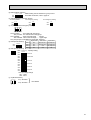
CONTENTS
INDOOR UNIT
FILTER
CHECK MODE
TEST RUN
REMOTE CONTROLLER
1. FEATURES ···········································3
2. PART NAMES AND FUNCTIONS ········7
3. SPECIFICATIONS·································8
4. DATA ···················································11
5. OUTLINES AND DIMENSIONS··········15
6. WIRING DIAGRAM·····························20
7. REFRIGERANT SYSTEM DIAGRAM ······21
8. OPERATION FLOW-CHART ··············22
9. MICROPROCESSOR CONTROL·······26
10. TROUBLESHOOTING ························49
11. DISASSEMBLY PROCEDURE ···········57
12. PARTS LIST········································62
13. OPTIONAL PARTS ·····························73
The Slim Line.
From Mitsubishi Electric.
1
FEATURES
Series PCH Ceiling Suspended
FILTER
CHECK MODE
TEST RUN
Indoor unit
Remote controller
Cooling capacity/Heating capacity
Service Ref.
W
Btu/h
PCH-2GKHA1
5,400 / 6,200 (7,600)
18,400 / 21,200 (25,900)
PCH-2.5GKHA1
7,000 / 7,100 (9,200)
23,900 / 24,200 (31,400)
7,500 / 8,500 (10,600)
25,600 / 29,000 (36,200)
10,000 / 10,450 (13,150)
34,100 / 35,700 (44,900)
PCH-5GKHSA1
12,400 /13,900 (16,900)
42,300 / 47,400 (57,700)
PCH-6GKHSA1
14,500 / 15,000 (18,000)
49,500 / 51,200 (61,400)
PCH-3GKHA1
PCH-4GKHSA1
w Rating Conditions
Cooling : Indoor
Outdoor
Heating : Indoor
Outdoor
(JIS B 8616)
o
o
: 27: (80 F)DB, 19: (66 F)WB.
o
o
: 35: (95 F)DB, 24: (75 F)WB.
o
: 20: (68 F)DB.
o
o
: 7: (45 F)DB, 6:(43 F)WB.
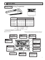
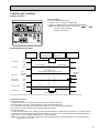
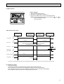
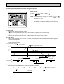
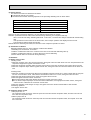
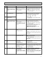
1. ADVANCED REMOTE CONTROLLER
● Operation buttons
● Once the operation of the unit is set, subsequent operation can
only be performed by pressing the ON/OFF button repeatedly.
button
button
This sets or switches the current time. start time and stop
time.
This switches between continuous operation and the
timer operation.
button
This sets the ventilation fan
speed.
ON/OFF button
button
This switches between the
operation and stop modes
each time it is pressed. The
lamp on this butoon lights
during operation.
Press this button to switch
the cooler electronic dry
(dehumidify) automatic and
heater modes.
FILTER
CHECK MODE
TEST RUN
TEMP button
This sets the room temparature The temparature setting
can be performed in 1°C
units
Setting range
Cooler 19°C to 30°C
Heater 17°C to 28°C
This model name of the
remote controller is indicated.
button
This adjusts the vertical angle
of the ventilation.
FILTER button
This resets the filter service
indication display.
4
button
This switches the horizontal
fan motion ON and OFF.
(This button dose not operate in
this model)
CHECK-TEST RUN button
Only press this button to perform an inspection check or
test operation. Do not use it
for normal operation.
3
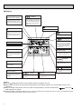
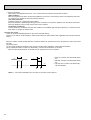
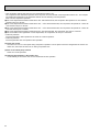
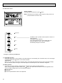
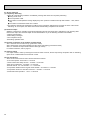
● Display
CENTRALLY
CONTROLLED display
This indicates when the unit is controlled by optional features such as
central control type remote controller.
display
The current time , start time and stop
time can be displayed in tensecond
intervals by pressing the time switch
button. The start time or stop time is
always displayed during the timer
operation.
display
display
This displays the air direction.
This indicates when the continous
operation and time operation modes
are set.
It also display the time for the timer
operation at the same time as when
it is set.
display
The selected fan speed is displayed.
display
This indicates the operation mode.
The temperature of the suction air is
displayed during operation. The display range is 8° to 39°C. The display
flashes 8°C when the actual temperature is less than 8° and flashes
39°C when the actual temperature is
greater than 39°C.
STANDBY display
Operation lamp
OPERATION MODE display
FILTER
CHECK MODE
TEST RUN
This indicates when the standby
mode is set from the time the sleep
operation starts until the heating air
is discharged.
This lamp lights during operation,
goes off when the unit stops and
flashes when a malfunction occurs.
4
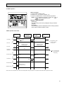
CHECK MODE
TEST RUN
DEFROST display
This display lights in the check mode
or when a test operation is performed.
This indicates when the defrost operation is performed.
FILTER
display
This lamp lights when the filter need
to be cleaned.
CHECK display
display
This indicates when a malfunction
has occurred in the unit which should
be checked.
display
This displays the selected setting
temperature.
display
This lamp lights when electricity is
supplied to the unit.
Caution
● Only the
display lights when the unit is stopped and power supplied to the unit.
● When power is turned ON for the first time the (CENTRAL CTRL) display appears to go off momentarily but this is not a
malfunction.
● When the central control remote control unit, which is sold separately, is used the ON-OFF button,
button and
TEMP button do not operate.
● “NOT AVAILABLE” is displayed when the k button are pressed.This indicates that this room unit is not equipped with the
fan direction adjustment function and the louver function.
4
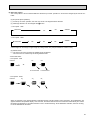
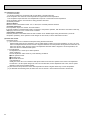
1. AIR OUTLET
New PCH series models have 1 air outlet (auto vane switching of horizontal air flow / down flow by switched by auto vane)
instead of 2 (horizontal,and down flows).
Protruding portion A
Unifies the air speed
with the vane.
2. EASY TO CLEAN ; FLOCKLESS VANE
B
With our original air current control mechanism, a flockless vane is
newly adapted.
The flockless vane prevents the condensation on the vane.
By changing the vane to the flockless type, the unit can be cleaned
much easier with mild household detergent.
Flockless vane
A
Air outlet
Protruding portion B
Sending the air to the upper
area of the vane
Prevents the air comes from
cntering from outside the unit
3. NEW MATERIALS FOR BETTER OIL RESISTANCE
We have changed the materials of grill, filer, fan and fan casing from ABS to P.P. (polypropylene) for better oil
resistance. As a result, oil crazing is cut in haif.
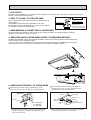
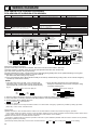
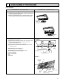
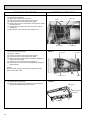
4. SIMPLIFIED INSTALLATION WORK (DIRECT SUSPENDING METHOD)
Simplified the installation work by changing the suspending method to the direct suspending method (suspending
the unit directly from the suspension fixture).
In this way, the unit can be attached to the suspension fixture without removing the installation parts off (Only the
side cover is removed). This method is much simpler than the “One-time installation method”.
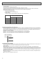
5. IMPROVING EFFICIENCY OF PIPING WORK
1 Removed the knockout work by separating the piping
space from the air outlet for efficiency of the piping work.
2 Improved the flexbility by making it possible for
drainage pipe to exit not only from the right side
back but also from the left side back.
Side panel
Back panel
Rubber plug
Drain pan
G L
open
G
D
L
U-cut
Insulation cover
(attached)
open
D
L : Liquid pipe
G : Gas pipe
D : Drain pipe
w Knockout work is needed for the top part. When optional drain-up machine is installed, the refrigerant pipe
exits out from the top.
Joint coupliy
(attached)
Insulation
cover
Drain pipe
(purchased locally)
Band
(attached)
w Please move the rubber plug for the unit to the right joint
when drainage pipe exits from the left side.
5
6. QUITENESS ; 43dB (HIGH NOTCH)
New PCH series has No.1 quietness by changing the air course and the adapting the new shape air outlet.
Auto vane
Swing
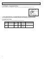
7. EASY MAINTENANCE ; NO MAINTENANCE NECESSARY FOR 2500 HOURS
The new longlife air filter can be used continuously 2500 hours without maintenance (at general office situation).
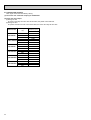
8. CHOICE OF FILTER
High performance filter can be purchaced optionally for the special needs.
Locations
6
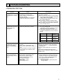
Appropriate filter
Capability
Filter life Maintenance How to attach to the unit
Busy
shops etc...
High performance filter
Weighing
method 70%
2500 hour
The filter can
be used again
after cleaning.
Remove the standard long life
filter before attach this optional
parts.
Regular
office, shops
Standard longlife filter
Weighing
method 30%
2500 hour
The filter can
be used again
after cleaning.
It is attached to the unit.
2
PART NAMES AND FUNCTION
● Indoor (Main) Unit
Left/right guide vanes
Change the direction of airflow
from the horizontal blower.
Air outlet
Long-life fillter
Removes dust and foreigh matter from air coming in
through the grille (Recommended cleaning interval :
Approx, every 2,500 operating hours)
Up/down guide vanes
Change the direction of airflow from the
vartical blower.
Air intake
Intake grille
7
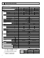
3
SPECIFICATIONS
Rating Conditions (JIS B8616)
Service Ref.
Item
Function
Btu/h
W
kW
Capacity
Total input
Service Ref.
Power supply
Input
Running current
Starting current
External finish
Heat exchanger
Fan(drive))No.
Fan motor output
Airflow(Low-High)
External static pressure
Booster heater
Operation control & Thermostat
Noise level(Low-High)
Cond. drain connection O.D.
INDOOR UNIT
kW
A
A
OUTDOOR UNIT
Dimensions
W
D
H
Weight
Service Ref.
Power supply
Input
Running current
Starting current
External finish
Refrigerant control
Compressor
Model
Motor output
Starter type
Protection devices
Heat exchanger
Fan(drive))No.
Fan motor output
Airflow
Defrost method
Crankcase heater
Noise level
Dimensions
REFRIGERANT
PIPING
kW
K/min <CFM>
Pa(mmAq)
kW
dB(A)
mm,(in)
mm,(in)
mm,(in)
mm,(in)
kg,(lbs)
kW
A
A
kW
kW
K/min <CFM>
W
D
H
Weight
Refrigerant
Charge
W
dB(A)
mm,(in)
mm,(in)
mm,(in)
kg,(lbs)
kg,(lbs)
Liquid
mm,(in)
Pipe size O.D.
Gas
mm,(in)
Indoor side
Connection method
Outdoor side
Height difference
Between the indoor & outdoor unit
Piping length
Notes1. Rating Conditions (JIS B8616)
Cooling : Indoor : 27:(80oF)DB. 19:(66oF)WB
Outdoor : 35:(95oF)DB. 24:(75oF)WB
Heating : Indoor : 20:(68oF)DB.
Outdoor : 7:(45oF)DB. 6:(43oF)WB
Refrigerant piping length (one way) : 5m(16ft)
3. Above data based on indicated voltage
Indoor Unit 1 phase 240V 50Hz
Outdoor Unit 1 phase 240V 50Hz
8
PCH-2GKHA1
PCH-2.5GKHA1
Cooling
Heating
Cooling
Heating
18,400
21,200 (25,900)
23,900
24,200 (31,400)
5,400
6,200 (7,600)
7,000
7,100 (9,200)
2.30
2.32 (3.72)
2.59
2.36 (4.46)
PCH-2.5GKHA1
PCH-2GKHA1
Single phase. 50Hz. 220-240V
0.10
0.10 (1.50)
0.13
0.13 (2.23)
0.43
0.43(6.21)
0.55
0.55 (9.30)
1.20
1.20 (6.98)
1.27
1.27 (10.02)
Munsell 0.70Y 8.59 / 0.97
Plate fin coil
Sirocco (direct))2
Sirocco (direct))3
0.054
0.07
10 -13 <353-459>
14 -18 <494-635>
0 (direct blow)
(1.4)
(2.1)
Remote controller & built-in
37 - 42
37 - 43
26(1)
1,000 (39-3/8)
1,310 (51-9/16)
680 (26-3/4)
210 (8-1/4)
36 (79)
28.5 (63)
PUH-2.5VKA2
PUH-2VKA2
Single phase. 50Hz. 220-240V
2.20
2.22
2.46
2.23
9.86
9.95
10.68
9.78
45
45
52
52
Munsell 5Y 7/1
Capillary tube
Hermetic
NH38VMD
NH41VMD
1.7
2.0
Line start
Internal thermostat. High-pressure switch
Plate fin coil
Propeller (direct)✕1
0.065
0.085
45 (1,590)
50 (1,764)
Reverse cycle
38
49
52
870 (34-1/4)
295 + 24 (11-5/8 add 1)
650 (25-5/8)
850 (33-7/16)
64 (141)
68 (150)
R-22
2.2 (4.9)
2.8 (6.2)
9.52 (3/8)
15.88 (5/8)
Flared
Flared
Max. 40m
Max. 50m
Max. 40m
Max. 50m
2. Guaranteed operating range
Cooling
Heating
Upper limit
Lower limit
Upper limit
Lower limit
Indoor
Outdoor
35: DB, 22.5: WB
46: DB
21: DB, 15.5: WB
-5: DB
27: DB
21: DB, 15.5: WB
20: DB
-8.5: DB, -9.5: WB
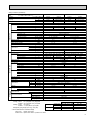
Rating Conditions (JIS B8616)
Service Ref.
Item
Function
INDOOR UNIT
Total input
Service Ref.
Power supply
Input
Running current
Starting current
External finish
Heat exchanger
Fan(drive))No.
Fan motor output
Airflow(Low-High)
External static pressure
Booster heater
Operation control & Thermostat
Noise level(Low-High)
Cond. drain connection O.D.
OUTDOOR UNIT
REFRIGERANT
PIPING
W
D
H
Weight
Service Ref.
Power supply
Input
Running current
Starting current
External finish
Refrigerant control
Compressor
Model
Motor output
Starter type
Protection devices
Heat exchanger
Fan(drive))No.
Fan motor output
Airflow
Defrost method
Crankcase heater
Noise level
Dimensions
Weight
Refrigerant
Charge
PCH-4GKHSA1
Cooling
Heating
Cooling
Heating
25,600
29,000 (36,200)
34,100
35,700 (44,900)
7,500
8,500 (10,600)
10,000
10,450 (13,150)
3.28
3.07 (5.17)
3.36
3.35(6.05)
PCH-4GKHSA1
PCH-3GKHA1
Single phase. 50Hz. 220-240V
kW
0.13
0.13 (2.23)
0.16
0.16 (2.86)
A
0.55
0.55 (9.30)
0.70
0.70 (11.95)
A
1.27
1.27 (10.02)
1.48
1.48 (12.73)
Munsell 0.70Y 8.59 / 0.97
Plate fin coil
Sirocco (direct) ✕ 3
0.07
0.09
kW
14 -18 <494-635>
20 -25 <706-883>
K/min <CFM>
0 (direct blow)
Pa(mmAq)
(2.1)
(2.7)
kW
Remote controller & built-in
37 - 43
40 - 45
dB(A)
mm,(in)
26 (1)
mm,(in)
1,310 ( 51-9/16 )
mm,(in)
680 (26-3/4)
mm,(in)
210 (8-1/4)
270 (10-5/8)
36 (79)
39.5 (87)
kg,(lbs)
PUH-3VKA2,PUH-3YKA2
PUH-4YKSA3
VKA...1phase, 50Hz, 220-240V / YK(S)A...3phase, 50-380Hz, 415V, 4wires
kW
3.15
2.94
3.20
3.19
A
13.82 / 5.16
12.89 / 4.81
5.24
5.22
A
58 / 37
58 / 37
40
40
Munsell 5Y 7/1
Capillary tube
Hermetic
NH56YDA
NH52VND(PUH-3VKA),NH52YDA(PUH-3YKA)
2.2 / 2.4
2.7
kW
Line start
Btu/h
W
kW
Capacity
Dimensions
PCH-3GKHA1
VKA...Inner thermostat. High-pressure switch YKA...Anti-phase protector, Thermal relay, Thermal switch, High-pressute switch
Plate fin coil
Propeller (direct) ✕ 1
0.085
50 (1,764)
kW
K/min <CFM>
Propeller (direct) ✕ 2
0.065 + 0.065
95 (3,350)
Reverse cycle
W
D
H
38
52
W
dB(A)
mm,(in)
mm,(in)
mm,(in)
kg,(lbs)
870 <34-1/4>
295 + 24 <11-5/8 add 1>
850 (33-7/16)
75 (165)
1,258 (49-1/2)
94 (207)
R-22
3.2 (7.1)
9.52 (3/8)
15.88 (5/8)
kg,(lbs)
Liquid
mm,(in)
Pipe size O.D.
Gas
mm,(in)
Indoor side
Connection method
Outdoor side
Height difference
Between the indoor & outdoor unit
Piping length
Notes1. Rating Conditions (JIS B8616)
Cooling : Indoor : 27:(80oF)DB. 19:(66oF)WB
Outdoor : 35:(95oF)DB. 24:(75oF)WB
Heating : Indoor : 20:(68oF)
Outdoor : 7:(45oF)DB. 6:(43oF)WB.
Refrigerant piping length (one way) : 5m(16ft)
38
54
4.2 (9.2)
9.52 (3/8)
19.05 (3/4)
Flared
Flared
Max. 50m
Max. 50m
2. Guaranteed operating range
Cooling
Heating
Upper limit
Lower limit
Upper limit
Lower limit
Indoor
Outdoor
35: DB, 22.5: WB
46: DB
21: DB, 15.5: WB
-5: DB
27: DB
21: DB, 15.5: WB
20: DB
-8.5: DB, -9.5: WB
3. Above data based on indicated voltage
Indoor Unit 1 phase 240V 50Hz
Outdoor Unit 1 phase 240V 50Hz / 3 phase 415V 50Hz
9
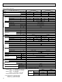
Rating Conditions (JIS B8616)
Service Ref.
Item
Function
Btu/h
W
kW
Capacity
Total input
Service Ref.
Power supply
Input
Running current
Starting current
External finish
Heat exchanger
Fan(drive))No.
Fan motor output
Airflow(Low-High)
External static pressure
Booster heater
Operation control & Thermostat
Noise level(Low-High)
Cond. drain connection O.D.
INDOOR UNIT
kW
A
A
OUTDOOR UNIT
Dimensions
W
D
H
Weight
Service Ref.
Power supply
Input
Running current
Starting current
External finish
Refrigerant control
Compressor
Model
Motor output
Starter type
Protection devices
Heat exchanger
Fan(drive))No.
Fan motor output
Airflow
Defrost method
Crankcase heater
Noise level
Dimensions
REFRIGERANT
PIPING
kW
K/min <CFM>
Pa(mmAq)
kW
dB(A)
mm,(in)
mm,(in)
mm,(in)
mm,(in)
kg,(lbs)
kW
A
A
kW
kW
K/min <CFM>
W
D
H
Weight
Refrigerant
Charge
W
dB(A)
mm,(in)
mm,(in)
mm,(in)
kg,(lbs)
kg,(lbs)
Liquid
mm,(in)
Gas
mm,(in)
Indoor side
Connection method
Outdoor side
Height difference
Between the indoor & outdoor unit
Piping length
Pipe size O.D.
Notes1. Rating Conditions (JIS B8616)
Cooling : Indoor : 27:(80oF)DB. 19:(66oF)WB
Outdoor : 35:(95oF)DB. 24:(75oF)WB
Heating : Indoor : 20:(68oF)DB.
Outdoor : 7:(45oF)DB. 6:(43oF)WB.
Refrigerant piping length (one way) : 5m(16ft)
3. Above data based on indicated voltage
Indoor Unit 1 phase 240V 50Hz
Outdoor Unit 3 phase 415V 50Hz
10
PCH-5GKHSA1
PCH-6GKHSA1
Heating
Cooling
Cooling
Heating
51,200 (61,400)
42,300
49,500
47,400 (57,700)
15,000 (18,000)
12,400
14,500
13,900 (16,900)
4.82 (7.82)
4.45
4.97
4.40 (7.40)
PCH-5GKHSA1
PCH-6GKHSA1
Single phase. 50Hz. 220-240V
0.24
0.24 (3.24)
0.24
0.24 (3.24)
1.06
1.06 (13.56)
1.06
1.06 (13.56)
2.20
2.20 (14.70)
2.20
2.20 (14.70)
Munsell 0.70Y 8.59 / 0.97
Plate fin coil
Sirocco (direct)✕4
0.15
27 -34 <953-1,200>
0 (direct blow)
(3.0)
Remote controller & built-in
41-46
42-48
26 (1)
1,620 (63-3/4)
680 (26-3/4)
270 (10-5/8)
48 (106)
46 (101)
PUH-6YKSA2
PUH-5YKSA3
3 phases. 50Hz. 380-415V (4 wires)
4.21
4.16
4.73
4.58
6.89
6.81
7.74
7.50
53
53
74
74
Munsell 5Y 7/1
Capillary tube
Hermetic
ZR61KC-TFD
ZR68KC-TFD
3.5
4.0
Line start
Anti-phase protector, Internal thermostat, Thermal switch, High-pressure switch
Plate fin coil
Propeller (direct)✕2
0.085 + 0.085
0.10 + 0.10
95 (3,350)
100 (3,530)
Reverse cycle
38
55
56
970 (38-3/16)
345 + 24 (13-9/16 add 1)
1,258 (49-1/2)
114 (251)
117 (258)
R-22
5.4 (11.9)
5.0 (11.0)
9.52 (3/8)
19.05 (3/4)
Flared
Flared
Max. 50m
Max. 50m
2. Guaranteed operating range
Cooling
Heating
Upper limit
Lower limit
Upper limit
Lower limit
Indoor
Outdoor
35: DB, 22.5: WB
46: DB
21: DB, 15.5: WB
-5: DB
27: DB
21: DB, 15.5: WB
20: DB
-8.5: DB, -9.5: WB
4
DATA
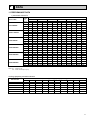
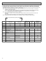
1. PERFORMANCE DATA
1) COOLING CAPACITY
Service Ref.
PCH-2GKHA1
PCH-2.5GKHA1
PCH-3GKHA1
PCH-4GKHSA1
PCH-5GKHSA1
PCH-6GKHSA1
Indoor
Intake
air
WB°C
16
18
20
22
16
18
20
22
16
18
20
22
16
18
20
22
16
18
20
22
16
18
20
22
20
CA
5448
5800
6157
6517
7062
7519
7981
8448
7566
8056
8551
9052
10088
10741
11402
12069
12510
13319
14138
14965
14628
15575
16532
17500
25
P.C.
1.84
1.88
1.92
1.95
2.08
2.12
2.16
2.20
2.63
2.68
2.73
2.78
2.69
2.75
2.80
2.85
3.57
3.64
3.71
3.78
3.98
4.06
4.14
4.22
CA
5299
5648
6012
6392
6869
7321
7794
8286
7359
7844
8350
8878
9812
10459
11134
11838
12167
12969
13806
14679
14228
15165
16144
17164
P.C.
1.92
1.96
2.00
2.04
2.16
2.21
2.25
2.30
2.74
2.80
2.85
2.91
2.81
2.87
2.92
2.98
3.72
3.79
3.87
3.95
4.15
4.24
4.32
4.41
Outdoor intake air DB°C
30
35
CA
P.C.
CA
P.C.
5104 2.07
4897 2.22
5442 2.12
5226 2.27
5798 2.16
5574 2.33
6171 2.21
5940 2.38
6616 2.33
6348 2.50
7054 2.38
6775 2.56
7515 2.44
7225 2.62
7999 2.49
7700 2.68
7089 2.95
6802 3.16
7558 3.02
7259 3.24
3.08
8052
7741 3.32
8571 3.15
8250 3.40
9452 3.02
9069 3.24
10078 3.09
9678 3.32
10736 3.16 10322 3.40
11427 3.23 11000 3.48
11720 4.00 11245 4.29
12496 4.10 12001 4.40
13313 4.19 12799 4.50
14170 4.27 13640 4.61
13705 4.47 13150 4.79
14613 4.57 14033 4.91
15568 4.67 14967 5.03
16570 4.77 15951 5.15
40
CA
P.C.
4678 2.37
5000 2.43
5341 2.49
5700 2.56
6064 2.67
6482 2.73
6923 2.81
7389 2.89
6515 3.38
6954 3.46
7419 3.55
7910 3.65
8686 3.46
9272 3.55
9892 3.64
10547 3.74
10771 4.58
11497 4.70
12266 4.82
13078 4.96
12595 5.12
13445 5.25
14344 5.39
15293 5.54
45
CA
P.C.
4447 2.52
4764 2.58
5099 2.66
5451 2.75
5765 2.84
6176 2.91
6609 3.00
7067 3.10
6199 3.59
6632 3.68
7089 3.79
7570 3.92
8266 3.68
8842 3.77
9451 3.89
10094 4.01
10249 4.87
10964 5.00
11720 5.15
12516 5.32
11985 5.44
12821 5.58
13705 5.75
14636 5.94
Notes CA : Capacity (W)
P.C. : Power consumption (kW)
Cooling cpapacity correction factors
Service Ref.
PCH-2GKHA1
PCH-2.5GKHA1
PCH-3GKHA1
PCH-4GKHSA1
PCH-5GKHSA1
PCH-6GKHSA1
5m
1.00
1.00
1.00
1.00
1.00
1.00
10m
0.992
0.989
0.981
0.989
0.981
0.975
15m
0.983
0.980
0.968
0.980
0.968
0.955
Refrigerant piping length (one way)
20m
25m
30m
35m
0.978
0.966
0.959
0.950
0.970
0.960
0.950
0.940
0.952
0.940
0.925
0.913
0.970
0.960
0.950
0.940
0.952
0.940
0.925
0.913
0.935
0.918
0.900
0.884
40m
0.945
0.930
0.900
0.930
0.900
0.869
45m
—
0.920
0.886
0.920
0.886
0.855
50m
—
0.910
0.874
0.910
0.874
0.840
11
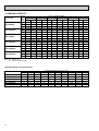
2. HEATING CAPACITY
Service Ref.
PCH-2GKHA1
PCH-2.5GKHA1
PCH-3GKHA1
PCH-4GKHSA1
PCH-5GKHSA1
PCH-6GKHSA1
Indoor
Intake
-10
air
CA
P.C.
DB°C
15
4246 1.58
20
4066 1.71
25
3907 1.81
15
4862 1.61
20
4656 1.73
25
4474 1.84
15
5821 2.09
20
5574 2.26
25
5356 2.40
15
7156 2.29
20
6852 2.46
25
6585 2.61
15
9519 3.00
20
9115 3.23
25
8759 3.43
15
10272 3.29
20
9836 3.54
25
9453 3.76
-5
CA
4866
4675
4485
5573
5354
5136
6671
6409
6149
8202
7880
7560
10910
10481
10056
11773
11311
10851
P.C.
1.75
1.89
2.01
1.78
1.92
2.04
2.31
2.49
2.66
2.53
2.72
2.90
3.32
3.58
3.81
3.63
3.92
4.17
Outdoor intake air WB°C
0
5
CA
P.C.
CA
P.C.
5546 1.93
6285 2.11
5337 2.08
6051 2.28
5125 2.22
5827 2.44
6351 1.96
7198 2.15
6112 2.11
6929 2.32
5869 2.26
6673 2.48
7604 2.55
8617 2.80
7317 2.75
8296 3.01
7027 2.94
7989 3.23
9348 2.78 10594 3.05
8996 3.00 10199 3.29
8639 3.20
9821 3.52
12434 3.65 14091 4.01
11966 3.94 13566 4.32
11491 4.21 13064 4.63
13418 4.00 15206 4.39
12912 4.31 14640 4.73
12400 4.61 14098 5.07
10
CA
P.C.
7082 2.31
6816 2.49
6590 2.67
8110 2.35
7806 2.53
7546 2.72
9710 3.06
9345 3.30
9034 3.53
11937 3.34
11488 3.60
11107 3.86
15878 4.39
15281 4.72
14774 5.07
17135 4.81
16491 5.18
15943 5.55
15
CA
P.C.
7936 2.52
7632 2.71
7413 2.91
9088 2.57
8740 2.76
8489 2.96
10880 3.34
10463 3.59
10163 3.85
13376 3.64
12863 3.92
12495 4.21
17792 4.78
17110 5.15
16620 5.52
19200 5.24
18464 5.64
17935 6.05
Notes CA : Capacity (W)
P.C. : Power consumption (kW)
Heating capacity correction factors
Service Ref.
PCH-2GKHA1
PCH-2.5GKHA1
PCH-3GKHA1
PCH-4GKHSA1
PCH-5GKHSA1
PCH-6GKHSA1
12
5m
1.00
1.00
1.00
1.00
1.00
1.00
10m
1.00
1.00
1.00
1.00
1.00
1.00
15m
1.00
1.00
1.00
1.00
1.00
1.00
Refrigerant piping length (one way)
20m
25m
30m
35m
1.00
1.00
1.00
0.998
1.00
1.00
1.00
0.998
1.00
1.00
1.00
0.998
1.00
1.00
1.00
0.998
1.00
1.00
1.00
0.998
1.00
1.00
1.00
0.998
40m
0.995
0.995
0.995
0.995
0.995
0.995
45m
—
0.993
0.993
0.993
0.993
0.993
50m
—
0.990
0.990
0.990
0.990
0.990
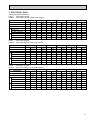
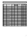
3. ELECTRICAL DATA
Rating Conditions (JIS B8616)
Indoor……220V 50Hz 1phase
Outdoor… 220V 50Hz 1phase / 380V 50Hz 3phase
PCH-2GKHA1 PCH-2.5GKHA1 PCH-3GKHA1 PCH-4GKHSA1 PCH-5GKHSA1 PCH-6GKHSA1
Cooling Heating Cooling Heating Cooling Heating Cooling Heating Cooling Heating Cooling Heating
5,300
6,100
[7,280]
[3.40]
0.38
6,900
7,000
[8,760]
2.52
2.27
[4.03]
Indoor
2.20
2.22
0.08
0.08
0.11
0.38
0.51
1.10
1.10
1.17
Outdoor
Service Ref.
Mode
Capacity (W)
Total Input (kW)
Input (kW)
Current (A)
Starting current (A)
Input (kW)
Current (A)
Starting current (A)
2.12
2.14
2.41
2.16
9.83
9.93
11.18
10.02
43
43
52
52
7,400
8,400
[10,160]
3.24
3.03
[4.79]
0.11
0.11
0.51
0.51
1.17
13,700
14,400
[17,320]
4.39
4.33
[6.85]
4.84
[7.28]
0.14
0.20
0.20
0.20
0.20
0.68
0.96
0.96
0.96
0.96
1.36
1.36
2.0
2.0
2.0
2.0
3.17
3.16
4.19
4.13
4.64
4.56
5.29
5.28
7.32
7.21
8.10
7.96
37
37
49
49
68
68
9,900
10,350
[12,620]
3.31
3.30
[5.57]
0.11
0.14
0.51
0.68
1.17
1.17
3.13
2.92
14.67/5.23 13.68/4.88
54 / 34
54 / 34
12,200
[16,220]
14,800
4.76
Indoor……230V 50Hz 1phase
Outdoor… 230V 50Hz 1phase / 400V 50Hz 3phase
Service Ref.
6,150
6,950
[8,980]
[3.56]
2.27
2.56
Indoor
Cooling Heating Cooling Heating Cooling Heating Cooling Heating Cooling Heating Cooling Heating
0.09
0.09
0.41
1.15
Outdoor
Mode
Capacity (W)
Total Input (kW)
Input (kW)
Current (A)
Starting current (A)
Input (kW)
Current (A)
Starting current (A)
PCH-2GKHA1 PCH-2.5GKHA1 PCH-3GKHA1 PCH-4GKHSA1 PCH-5GKHSA1 PCH-6GKHSA1
7050
7,450
[10,380]
[4.25]
2.32
3.26
0.12
0.12
0.41
0.53
1.15
1.22
2.16
9.78
2.18
2.44
2.20
9.87
10.94
9.86
44
44
52
52
5,350
[7,440]
2.25
8,450
9,950
[12,880]
10,400
12,300
[16,560]
[4.98]
3.05
3.34
[5.81]
3.33
4.42
0.12
0.12
0.15
0.15
0.53
0.53
1.22
1.22
0.53
0.69
1.22
1.42
3.14
2.93
14.22 / 5.21 13.27 /4.86
56 / 36
56 / 36
13,800
14,450
[17,660]
14,900
[7.13]
4.37
4.91
[7.55]
0.22
0.22
0.22
0.22
0.69
1.01
1.01
1.01
1.01
1.42
2.10
2.10
2.10
2.10
3.19
3.18
4.20
4.15
4.69
4.57
5.23
5.22
7.05
6.97
7.87
7.67
39
39
51
51
71
71
4.79
Indoor……240V 50Hz 1phase
Outdoor… 240V 50Hz 1phase / 415V 50Hz 3phase
Service Ref.
6,200
[7,600]
2.30
2.32
[3.72]
0.43
7,000
7,100
[9,200]
2.59
2.36
[4.46]
Indoor
5,400
0.10
0.10
0.13
0.43
0.55
1.20
1.20
Outdoor
Mode
Capacity (W)
Total Input (kW)
Input (kW)
Current (A)
Starting current (A)
Input (kW)
Current (A)
Starting current (A)
PCH-2GKHA1 PCH-2.5GKHA1 PCH-3GKHA1 PCH-4GKHSA1 PCH-5GKHSA1 PCH-6GKHSA1
Cooling Heating Cooling Heating Cooling Heating Cooling Heating Cooling Heating Cooling Heating
2.20
2.22
9.86
45
7,500
8,500
[10,600]
3.28
3.07
[5.17]
0.13
0.13
0.55
0.55
1.27
1.27
2.46
2.23
9.95
10.68
9.78
45
52
52
13,900
14,500
[18,000]
4.45
4.40
[7.40]
4.97
[7.82]
0.16
0.24
0.24
0.24
0.24
0.70
1.06
1.06
1.06
1.06
1.48
1.48
2.20
2.20
2.20
2.20
3.20
3.19
4.21
4.16
4.73
4.58
5.24
5.22
6.89
6.81
7.74
7.50
40
40
53
53
74
74
10,000
10,450
[13,150]
3.36
3.35
[6.05]
0.13
0.16
0.55
0.70
1.27
1.27
3.15
2.94
13.82 / 5.16 12.89 / 4.81
58 / 37
58 / 37
12,400
[16,900]
15,000
4.82
13
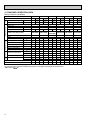
4. STANDARD OPERATION DATA
Rating Conditions (JIS B8616)
Total
V
A
Outdoor Indoor side Refrigerant circuit
side
W
KW
Electrical circuit
Service Ref.
Mode
Capacity
Input
Indoor unit Service Ref.
Phase, Hz
Volts
Amperes
Outdoor unit Service Ref.
Phase, Hz
Volts
Amperes
Discharge pressure
Suction pressure
Discharge temperature
Condensing temperature
Suction temperature
Ref. pipe length
Intake air temperature
Discharge air temperature
Intake air temperature
SHF
BF
V
A
Mpa·G(Of/F·G)
Mpa·G(Of/F·G)
°C
°C
°C
m
DB °C
WB °C
DB °C
DB °C
WB °C
PCH-2GKHA1 PCH-2.5GKHA1 PCH-3GKHA1 PCH-4GKHSA1 PCH-5GKHSA1 PCH-6GKHSA1
Cooling Heating Cooling Heating Cooling Heating Cooling Heating Cooling Heating Cooling Heating
6,200
7,100
8,500
10,450
15,000
5,400 [7,600]
7,000 [9,200]
7,500 [10,600]
10,000 [13,150]
12,400 13,900
[16,900] 14,500 [18,000]
2.32
2.36
3.07
3.35
4.40
4.82
2.30 [3.72]
2.59 [4.46]
3.28 [5.17]
3.36 [6.05]
4.45 [7.40]
4.97 [7.82]
PCH-2GKHA1 PCH-2.5GKHA1 PCH-3GKHA1 PCH-4GKHSA1 PCH-5GKHSA1 PCH-6GKHSA1
1, 50
1, 50
1, 50
1, 50
1, 50
1, 50
240
240
240
240
240
240
0.43 0.43 0.55 0.55 0.55 0.55 0.70 0.70 1.06 1.06 1.06 1.06
PUH-3VKA2
PUH-4YKSA3 PUH-5YKSA3 PUH-6YKSA2
PUH-2VKA2 PUH-2.5VKA2
PUH-3YKA2
1, 50
1, 50
1/3, 50
3, 50
3, 50
3, 50
240
240
240 / 415
415
415
415
9.86 9.95 10.68 9.78 13.82/ 5.16 12.89/ 4.81 5.24 5.22 6.89 6.81 7.74 7.50
1.92
1.90
2.05
1.73
2.04
1.94
1.83
1.72
1.78
1.97
1.80
(19.4)
(20.9)
(17.6)
(20.8)
(19.8)
(18.7)
(17.5)
(19.6)
(18.1)
(20.1)
0.47
(4.8)
0.37
(3.77)
0.53
(5.4)
0.38
(3.87)
0.43
(4.39)
0.36
(3.67)
0.50
(5.1)
0.39
(3.98)
0.48
(4.90)
0.37
(3.77)
0.45
(4.59)
(3.88)
87
50
3.8
5
27
19
11.5
35
24
0.68
0.11
89
—
-2.7
5
20
15
44.8
7
6
—
—
85
53
6.9
5
27
19
12.4
35
24
0.69
0.14
77
—
-2.1
5
20
15
40.4
7
6
—
—
87
53
1.6
5
27
19
11.1
35
24
0.66
0.15
83
—
-2.9
5
20
15
44.8
7
6
—
—
78
48
6.7
5
27
19
11.1
35
24
0.68
0.12
75
—
-1.0
5
20
15
42.1
7
6
—
—
75
50
4.4
5
27
19
12.4
35
24
0.73
0.07
70
—
-2.8
5
20
15
42.4
7
6
—
—
74
51
2.6
5
27
19
10.0
35
24
0.65
0.14
69
—
-1.8
5
20
15
44.9
7
6
—
—
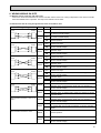
The unit of pressure has been changed to Mpa on the international system of unit (SI unit system).
The converted score against the traditional unit system can be gotten according to the formula below.
Of/F
F·G)
1(Mpa·G)=10.2(O
14
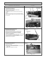
1.92
(19.6)
(18.4)
0.38
1
2
3
4
When electrical
box is pulled
down
42
179
3
6~7
2
928
7
Electrical box 70
525
Celling
8
226
86
2
138
171
263
352
5
1 4
46 175
131
Electrical box [Front view]
32
161
Air intake
Air outlet
17
150
918
1000
904
983
933 (suspension bolt pitch)
140
6
70
15
85
(3/8F) liquid
(5/8F) gas
(Drainage)
182
201
241
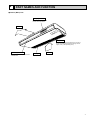
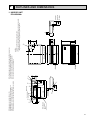
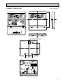
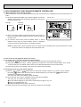
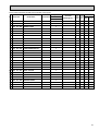
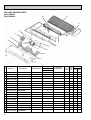
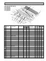
NOTES:
1. Use M10 or W3/8 screws for anchor bolt.
2. Please be sure when installing the drain-up machine (option parts).
refrigerant pipe will be only upper drain pipe arrangement.
80
320
180
210
3879
38
5 Refrigerant-pipe connection (liquid pipe side/flared connection)
6 Knock out hole for upper drain pipe arrangement
7 Knock out hole for left drain pipe arrangement
8 Knock out hole for wining arrangement
81 76
254
1. INDOOR UNIT
PCH-2GKHA1
680
Drainage pipe connection (26mm I.D.)
Drainage pipe connection (for the left arrangement)
Knock out hole for left drain-piping arrangement
Refrigerant-pipe connection (gas pipe side/flared connection)
157
5
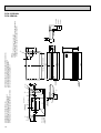
OUTLINES AND DIMENSIONS
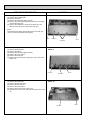
15
179
When electrical
box is pulled
down
42
32
161
1235
7
Electrical box
525
Celling
70
[ Front view ]
8
226
2
86
138
171
263
416
5
1 4
Air outlet
Air intake
131
Electrical box
3879
38
3
2
46 175 1
17
6~7
150
1228
1310
1214
1290
1240 (suspension bolt pitch)
140
70
6
80
15
85
(3/8F liquid)
(5/8F gas)
(Drainage)
182
201
241
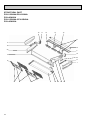
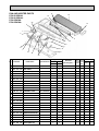
NOTES:
1. Use M10 or W3/8 screws for anchor bolt.
2. Please be sure when installing the drain-up machine (option parts).
refrigerant pipe will be only upper drain pipe arrangement.
5 Refrigerant-pipe connection (liquid pipe side/flared connection)
6 Knock out hole for upper drain pipe arrangement
7 Knock out hole for left drain pipe arrangement
8 Knock out hole for wining arrangement
210
Drainage pipe connection (26mm I.D.)
Drainage pipe connection (for the left arrangement)
Knock out hole for left drain-piping arrangement
Refrigerant-pipe connection (gas pipe side/flared connection)
81 76
254
320
180
680
16
157
1
2
3
4
PCH-2.5GKHA1
PCH-3GKHA1
1
2
3
4
239
2
When electrical
box is pulled
down
42
93
7
Electrical box
525
160
3
70
229
1235
Celling
8
38 140
2
687
38
86
138
171
263
5
192
4
Air intake
Air outlet
1
1
236
45
17
1228
1310
1214
1240 (suspension bolt pitch)
150
[ Front view ]
140
70
6
81 96
254
80
320
207
680
Electrical box
270
6~7
16
87
245
182
(Drainage)
(5/8F-gas)
(3/8F liquid)
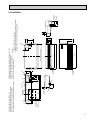
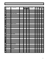
5 Refrigerant-pipe connection (liquid pipe side/flared connection)
6 Knock out hole for upper drain pipe arrangement
7 Knock out hole for left drain pipe arrangement
NOTES:
8 Knock out hole for wining arrangement
1. Use M10 or W3/8 screws for anchor bolt.
2. Please be sure when installing the drain-up machine (option parts).
refrigerant pipe will be only upper drain pipe arrangement.
217
Drainage pipe connection (26mm I.D.)
Drainage pipe connection (for the left arrangement)
Knock out hole for left drain-piping arrangement
Refrigerant-pipe connection (gas pipe side/flared connection)
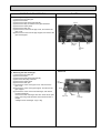
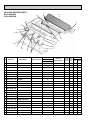
PCH-4GKHSA1
17
239
42
When electrical
box is pulled
down
Electrical box
93
6~7
7
Electrical box
525
160
229
1545
70
Celling
[ Front view ]
2
8
38 140
38
86
138
171
263
687
5
1
4
1
236
Air intake
Air outlet
45
3
2
192
1535
1620
1524
1547(suspension bolt pitch)
18
140
70
6
16
87
(3/8F liquid)
(3/4F gas)
(Drainage)
182
198
245
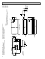
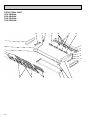
NOTES:
1. Use M10 or W3/8 screws for anchor bolt.
2. Please be sure when installing the drain-up machine (option parts).
refrigerant pipe will be only upper drain pipe arrangement.
5 Refrigerant-pipe connection (liquid pipe side/flared connection)
6 Knock out hole for upper drain pipe arrangement
7 Knock out hole for left drain pipe arrangement
8 Knock out hole for wining arrangement
81 96
80
320
207
680
150
Drainage pipe connection (26mm I.D.)
Drainage pipe connection (for the left arrangement)
Knock out hole for left drain-piping arrangement
Refrigerant-pipe connection (gas pipe side/flared connection)
217
1
2
3
4
270
18
254
PCH-5GKHSA1
PCH-6GKHSA1
2. REMOTE CONTROLLER
Unit : mm(inch)
FILTER
CHECK MODE
TEST RUN
TEST RUN
120
FILTER
CHECK MODE
18
130
83.5
Rear side wiring arrangement opening.
46
CAUTION
SW18
SW17
19
6
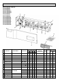
WIRING DIAGRAM
PCH-2GKHA1/PCH-2.5GKHA1/PCH-3GKHA1
PCH-4GKHSA1/PCH-5GKHSA1/PCH-6GKHSA1
SYMBOL
C
CN1<R.B>
CN2<R.B>
CN2L<I.B>
CNP<I.B>
CN50<I.B>
CN51<I.B>
F1,2<I.B>
FS1,2
NAME
SYMBOL
FAN MOTOR CAPACITOR
PROGRAM TIMER CONNECTOR
REMOTE SWITCH CONNECTOR
LOSSNAY CONNECTOR
DRAIN-UP MACHINE CONNECTOR
DRAIN SENSOR CONNECTOR
CENTRALLY CONTROL CONNECTOR
FUSE(6.3A 250V)
THERMAL FUSE(98:10A:2GKHA / 117:16A:
4GKHA110:16A:2.5,3GKHA.5.6GKHSA)
HEATER
INDOOR CONTROLLER BOARD
FUNCTION SELECTOR JUMPER RESISTORS
MODEL SELECTOR JUMPER RESISTORS
H
I.B
J1<I.B>
J5<I.B>
NAME
J9<I.B>
LED1<I.B>
LED2<I.B>
MF
MV
R.B
RT1
RT2
SW2<I.B>
SW3<I.B>
SW6<I.B>
SW7<I.B>
RED
ORN
YLW
(OPTION)
WHT
YLW
RED
BLU
RED
RED
BRN
BRN
BLU
BLU
3 2 1
BRN
ORN
YLW
BLK
BLK
TB5
TB4
2 1
2 1
RED
BLU
FS1
H
FS2
YLW
YLW
3
2
1
88H
1 GRY
RED
26H
PCH-2~6GKH(S)A (with heater)
OUTDOOR UNIT
R.B
TO OUTDOOR UNIT
CONNECTING WIRES
DC12V
RT2
RT1
6
RED
TRANSMISSION WIRES
2 DC12V
1
CN50
DRAIN
SW18
MODELS
GRY
BLK
TB6
OFF
ON
SW7
MODELS
2
CN2L
SW7
1
LOSSNAY
5 4 3
2 1
INTAKE
I.B
REMOTE CONTROLLER
2 1
CN30
4 3 2 1
CN50
4 5 6 7 8 9 10
5 4 3 2 1
123456
DRAIN
1 2 1234
ON
OFF
CN24
23 4
J1
HEATER
J9
PIPE
CN20
12
SW6
J5
CN40
1234
CN21
CN51
ON
OFF
SW2
REMOCON
POWER
LED1 12V
POWER
SW3
SW7
MV
INDOOR UNIT
CN22
1
ZNR
CENTRALLY
CONTROL
X4
LED2 5V
POWER
TO
OUTDOOR
REMOCON
F1
CN6V
F2
6
4 3 2 1 CN4T
TRANS
6
CNP
D.U.M
VANE
X4
1 3 CNT
TRANS
POWER
5
6 5
CND 1 3
1 3
1 3 5
88H
TB2
14.3VAC
6
2 1
FAN1
RED
3
RED
BLU
L
N
TB2
T
LINE TRANSMISSION
FAN MOTOR RELAY
VARISTOR
HEATER THERMAL SWITCH
HEATER CONTACTOR
OPTION DRAIN-UP MACHINE
OPTION DRAIN-UP SENSOR
CN24
I.B
GRN/YLW
X4<I.B>
ZNR
26H
88H
DP
DS
HEATER
RED
WHT
BLK
C
10VAC
220V
230V
240V
TB4
TB5,6
ADDRESS SELECTOR
FUNCTION SELECTOR
TRANSFORMER
POWER SUPPLY TERMINAL BLOCK
INDOOR/OUTDOOR CONNECTING WIRE TERMINAL BLOCK
REMOTE CONTROLLER TERMINAL BLOCK
1 2
DP
POWER SUPPLY
~(1 PHASE)
AC220-240V 50Hz
AC220V 60Hz
NAME
SW17<R.B>
SW18<R.B>
T
TB2
ROOM TEMPERATURE THERMISTOR
(0:/15k", 25:/5.4k" DETECT)
INDOOR COIL THERMISTOR
(0:/15k", 25:/5.4k" DETECT)
ADDRESS SELECTOR
EMERGENCY OPERATION SWITCH
TWIN/TRIPLE SELECTOR
MODEL SELECTOR
L
N
MF
SYMBOL
MODEL SELECTOR JUMPER RESISTORS
DC 12V POWER LED
DC 5V POWER LED
FAN MOTOR
VANE MOTOR
REMOTE CONTROLLER BOARD
DS(OPTION)
2GK(H)
ON
OFF
2.5GK(H)
3GK(H)
ON
OFF
ON
OFF
1234
1234
1234
4GK(H)
5GK(H)
6GK(H)
ON
ON
ON
OFF
OFF
OFF
1234
1234
1234
4321
5 4 3 2 1
SW17
OFF
ON
87654321
A.1 B.2
CN1
CN2
3 2 1
BG79Y189H03-A
[Emergency operation procedure]
(2) Turn on the outdoor unit side circuit breaker, then indoor unit side circuit breaker in this order.
(3) During emergency operation indoor fan runs at high speed but automatic vane remains stop.
(4) If vane closed, open the vane by hand slowly.
(5) Thermostat will not function. Cold air belows out for defrosting during heating thus do not operate defrosting for a long time.
(6) Emergency cooling should be limited to 10 hours maximum.
(The indoor unit heat exchanger may freeze).
(7) If the microcomputer doctor detects the abnormality of the drain-up machine during cooling mode, do not execute emergency
operation.(If causes drain overflow)
NOTES :
1. Since the indoor fan motor (MF 1.2) is connected with
2. Since the indoor transformer (T)is connected with
230~240V power. IF 220V power is used. change the dip
240Vpower.if 220.230V power is used. Change the wiring
switch (SWS<1.B>)on the indoor controller board showing
connection showing fig:w2.
fig:w1.
fig:w1 Indoor fan motor (MF) for
fig:w2 When power supply is
ON
OFF 1 2 3 4
ON
OFF 1 2 3 4
230V
220V
240V YELLOW
230V ORANGE
220V RED
3. Since the outdoor side electric wiring may change be sure to check the outdoor unit electric wiring for servicing.
4. Indoor and outdoor connecting wires are made with polarities. make wiring matching terminal numbers.
5. Symbols used in wiring diagram above are.
: Connector, / : Terminal block.
6. Emergency operation
If remote controller or microcomputer fails but there is no other truble. emergency operation is possible by setting dip switch
(SW3<I.B>) on the indoor controller board.
[Check items]
(1)Make sure that no other trouble exist the outdoor unit. Trouble with the outdoor unit prevents emergency operation.
(If any trouble exists the outdoor unit error code “P8”will be displayed on the remote controller and the trouble position will be shown
on the outdoor controller LED. See electric wiring diagram of the outdoor unit for details.)
(2)Make sure that there is no trouble with the indoor fan.
Emergency operation will be continuous operation mode due to power ON/OFF (ON/OFF with the remote controller is not possible).
[Emergency operation procedure]
(1)Set the dip switch (SW3<I.B>) on the indoor controller board to 1 on and 2 off for cooling and 1 - 2 on for heating.
20
7
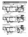
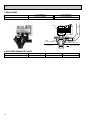
REFRIGERANT SYSTEM DIAGRAM
PCH-2GKHA1/PUH-2VKA2
PCH-2.5GKHA1/PUH-2.5VKA2
PCH-3GKHA1/PUH-3VKA2,PUH-3YKA2
Unit : mm
Refrigerant flow in cooling
Refrigerant flow in heating
Oil separator
Refrigerant pipe
(option)
4-way valve
15.88mm( 5/8")
Ball valve
(with heat insulator)
Strainer
Indoor unit
High pressure
control switch
Outdoor unit
Outdoor heat exchanger
Service
port
Outdoor
coil
thermistor
(RT)
Flexible tube
Indoor
heat
exchanger
Service
port
Flared
connection
Strainer
Bypass
valve
Restrictor
valve
Accumulator
Indoor coil
thermistor
RT2
Restrictor
valve
Strainer
Refrigerant pipe Ball valve
(option)
(with service port)
9.52mm( 3/8")
(with heat insulator)
PCH-2(O.D.4.0 ✕ I.D.2.0-R430)
PCH-2.5(O.D.4.0 ✕ I.D.2.4-R1550)
PCH-3(O.D.4.0 ✕ I.D.2.4-R1070)
Capillary
tube
PCH-2(O.D.3.2 ✕ I.D.1.6-R230)
PCH-2.5(O.D.3.2 ✕ I.D.1.8-R430)
PCH-3(O.D.4.0 ✕ I.D.2.0-R280)
PCH-4GKHSA1/PUH-4YKSA3
Oil separator
Refrigerant pipe
(option)
4-way valve
19.05mm( 3/4)
Ball valve
(with heat insulator) Strainer
Indoor unit
High pressure
control switch
Outdoor unit
Outdoor heat exchanger
Service
port
Outdoor
coil
thermistor
(RT)
Flexible tube
Indoor
heat
exchanger
Service
port
Restrictor
valve
Capillary
tube
Restrictor
valve
Flared
connection
Strainer
Distributor
with
strainer
Capillary
tube
Compressor
Distributor
with
strainer
Indoor coil
thermistor
RT2
<R.V.coil>
Heating ON
Cooling OFF
Bypass
valve
Accumulator
Capillary
tube
(O.D.3.2✕ I.D.2.0-R820)✕ 2
Compressor
Strainer
Ball valve
Refrigerant pipe
(option)
(with service port)
9.52mm( 3/8")
(with heat insulator)
(O.D.4.0 ✕ I.D.2.0-R350)
PCH-5GKHSA1/PUH-5YKSA3
PCH-6GKHSA1/PUH-6YKSA2
Oil
separator
Refrigerant pipe
(option)
4-way valve
19.05mm( 3/4")
Ball valve
(with heat insulator) Strainer
Indoor unit
Outdoor unit
Outdoor heat exchanger
Service
port
Outdoor
coil
thermistor
(RT)
Flexible tube
Indoor
heat
exchanger
Service
port
Strainer
Indoor coil
thermistor
RT2
High pressure
control switch
Flared
connection
Restrictor valve
Distributor
with
strainer
Capillary
tube
PCH-5
PCH-6
Bypass
valve
Accumulator
Ball valve
Refrigerant pipe
(with service port)
(option)
9.52mm( 3/8")
(with heat insulator)
Compressor
Restrictor
valve
Capillary
tube
Capillary tube
Strainer
PUH-5
Thermal switch PUH-6
(O.D.4.0 ✕ I.D.2.4-R840)✕ 2
(O.D.4.0 ✕ I.D.2.4-R1200)✕ 2
O.D.4.0 ✕ I.D.2.4-R270
O.D.4.0 ✕ I.D.3.0-R300
21
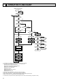
8
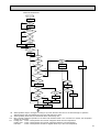
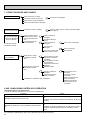
OPERATION FLOW-CHART
MAIN OPERATION
START
Power circuit
breaker
1
NO
YES
YES
Check SW
ON twice
NO
Operation SW
ON
w1
YES
NO
“OFF” timer
YES
NO
NO
Set time
complete
“ON” timer
YES
YES
YES
Set time
complete
NO
w2
NO
NO
Trouble
Remote controller
operation display
YES
STOP
Trouble STOP
PROTECTION DEVICE
SELF HOLD RELEASE
PROTECTION DEVICE
SELF HOLD
Operating mode
(COOL)
NO
Operating mode
(DRY)
w3
Remote controller
indicator lamp OFF
Remote controller
trouble display
NO
Operating mode
(HEAT)
Indoor side
w4
Fan STOP
NO
w6
Operating mode
(FAN)
NO
Auxiliary heater OFF
Auto COOL/HEAT
operation
Outdoor side
w5
Compressor OFF
Fan STOP
Four-way valve OFF
w1 In addition, the centralized control and remote control can be operated.
w2 The modes which indicate the sources of trouble are listed below.
● EO-Signal transmitting/receiving error
● P1-Room temperature thermistor malfunction
● P2-Indoor coil thermistor malfanction
● P4-Drain sensor malfunction
● P5-Drain overflow
● P6-Coil frost/overheat protection
● P7-System error
● P8-Outdoor unit trouble
w3 The CHECK swich will show if an error has occurred in the past.
w4 Fan runs on low speed for 1 minute in order to remove overheat air.
w5 The 3-minute (6 minutes … heating mode) time-delay functions after compressor stops.
w6 FAN or AUTO mode is selected by the indoor dipswitch setting.
w7 In FAN mode, fan speed and vane operation depend on the remote controller setting. (Compressor is OFF.)
22
YES
COOL operation
YES
DRY operation
YES
HEAT operation
YES
w7
FAN operation
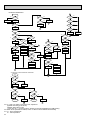
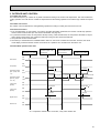
COOLING OPERATION
COOL operation
Four-way valve/OFF
NO
w8
Initial
COOLING
YES
Vane intial
setting
Vane
40 deg downward angle
60 deg downward angle
NO
YES
NO
Fan speed
LOW
YES
NO
Vane setting notch
Downward discharge
1 hour
YES
Vane horizontal
airflow
w9
NO
Compressor
thermostat
ON
YES
NO
Allowance
cancel
NO
YES
3-minute
time delay
YES
6-minute
time delay
NO
3-minute
compressor operation
NO
Allowance
period
NO
6 minute
time delay
NO
YES
Allowance set
w10
Coil frost protection
YES
YES
Coil frost
prevention
NO
w11
NO
Cooling area
YES
NO
10-minute
compressor operation
NO
YES
1 min continue
YES
Allowance cancel
FAN speed
LOW
Coil frost
protection
YES
NO
NO
Indoor coil
tempreature is
10°C or higher
16-minute
compressor operation
YES
Indoor pipe
temperature is
1°C or lower
NO
Compressor ON
YES
YES
Coil frost
prevention
NO
FAN speed
LOW 5 min
elapse
NO
YES
Outdoor unit
trouble
3-minute
time delay
Coil frost
prevention release
Compressor OFF
1
w8
w9
w10
w11
When operation stops or changes to cooling or dry mode, the auto vane turns to a horizontal angle. If operation
changes during auto vane SWING, the auto vane will continue to swing.
When operating TEST RUN, the thermostat will be continuously ON.
After 3 minute compressor operation, if the indoor coil thermistor reads -15°C or below for 3 minutes, the compressor
will stop for 6 minutes.
Cooling area : Indoor coil temperature is more than 5 degrees above the room temperature.
Heating area : Indoor coil temperature is more than 5 degrees below the room temperature.
FAN area
: Indoor coil temperature is within 5 degrees either way of the room temperature.
23
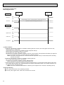
HEATING OPERATION
A
Heat operation
NO
Initial
HEATING
w15
11
YES
Defrost release
Outdoor unit trouble
NO
Indoor coil
thermistor is 60°C
or higher
NO
FAN speed
Low notti
NO
Four-way valve ON
1
YES
Hor adjust
in process
YES
Airflow 10% up
NO
YES
Compressor ON
YES
NO
w9
10-minute
compressor
operation
YES
NO
YES
Compressor
thermostat ON
3 min.restart
prevention
2
NO
w11
Indoor piping
-15°C or lower
YES
Heating
area
NO
Auxiliary heater
ON
NO
FAN STOP
Outdoor unit
trouble
FAN SPEED very low
w11
NO
YES
FAN SPEED
Very low airflow
NO
YES
Airflow area
20 min.elaspe
Compressor ON
Airflow area
Heating area
YES
FAN SPEED
Low
NO
A
Hot adjust start
YES
NO
Auxiliary heater
thermostat ON
YES
YES
Indoor piping
60°C or higher
Auxiliary heater ON
w10
Outdoor unit
trouble
w11
Overheat remote
START
NO
Airflow area
Cooling area
NO
Indoor unit
70°C or higher
YES
YES
Defrost operation
START
Allowance
period
Four-way valve
OFF
YES
Overload protect
NO
6-minute restart
prevention
Allowance set
1
Compressor OFF
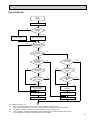
AUTOMATIC COOLING/HEATING OPERATION
Auto COOL/HEAT
operation
NO
1
w16
Initial mode
w17
YES
NO
T1 >
=T0
YES
COOL mode
COOL mode
HEAT mode
NO
YES
NO
NO
T1 < (T0 - 2)
YES
After 15min.
T1<(T0-2)
After 15min.
T1>(T0 + 2)
YES
NO
NO
COOL operation
T1>(T0 + 2)
YES
YES
HEAT operation
1
HEAT operation
Cool mode
set
1
w15 ( i ) Until Low airflow is set while in hot adjustment
( ii )While defrosting (FAN STOP)
(iii)When thermostat is OFF
In the case of( i ), (ii) and (iii) above, airflow is horizontal regardless the VANE setting.
w16 When AUTO operation is started, COOL or HEAT mode is selected automatically.
w17 T1 : Room temperature.
To : Set temperature
24
FAN SPEED
Low 2 min.
elapse
YES
FAN SPEED
setting nitch
Hot adjust
release
YES
Auxiliary heater OFF
NO
Compressor OFF
NO
YES
Indoor piping
55°C or lower
6 min. restart
prevention
B
NO
Allowance cancel
NO
Indoor piping
35°C or higher
HOT adjust
6 min. elapse
B
Allowance cancel
YES
NO
NO
2
YES
YES
3-minute
Auxiliary heater
OFF
NO
Defrost
30 min. elapse
NO
Defrosting
NO
NO
NO
Vane initial setting
Vane setting notch
PCH-GKH(S)A
Type
YES
Heating area
NO
FAN setting notch
DRY OPERATION
DRY
operation
Four-way valve / OFF
NO
Initial dry
operation
w8
YES
Vane
setting notch
Vane initial setting
YES
Room tempereature is
18°C or lower
w12
NO
NO
During
compressor ON
YES
3-minute
compressor
operation
NO
NO
YES
NO
w9
Compressor &
thermostat ON
YES
Compressor &
thermostat
ON
w9
NO
YES
NO
Compressor ON
time completes
10-minute
compressor
OFF
NO
YES
YES
w13
10-minute compressor
OFF timer start
Compressor ON
time set
Compressor OFF
Compressor ON
w14
Fan STOP
YES
3-minute
time delay
w14
Fan speed LOW
1
w8—9 Refer to page 31~32.
w12
When room temperature is 18°C or below, the compressor cannot operate.
When room temperature rises over 18°C, the compressor starts after a 3-minute time delay.
w13
Compressor ON time is decided by room temperature. Refer to page 31~32.
w14
In dry operation, compressor ON makes the fan speed LOW and compressor OFF stops the fan.
It is not possible to set the fan speed with the remote controller.
25
9
MICROPROCESSOR CONTROL
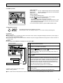
1.OUTLINE OF MICROPROCESSOR CONTROL
INPUT to remote controller
● OFF-ON switching.
● COOL/DRY-AUTO-HEAT selector switching.
● Thermostat setting.
● TIMER mode selector-switching and Timer
setting.
● HIGH-LOW fan speed switching.
● AUTO Vane selector (AIR DISCHARGE)
switching.
● TEST RUN switching.
● CHECK mode switching.
(Self diagnostic trouble shooting)
Remote controller board
● Processes and transmits
orders.orders.
OUTPUT to remote controller
Remote controller
● LCD indicator
FILTER
CHECK MODE
TEST RUN
4
Indoor
unit
12VDC
Non-polar, two-wire cable
maximum length 500 meters
INPUT from indoor unit
● Room temperature thermistor (RT1)
● Indoor coil thermistor (RT2)
● Drain sensor
OUTPUT to indoor unit
Signal
Indoor controller board
● Receives orders from remote controller and
temperature data from indoor unit.
● Processes orders and data.
● Controls indoor and outdoor operation.
● Self diagnostic function.
w System control operation.
w Emergency operation.
w Set by dipswitch on indoor controller board.
● Transmits the power to remote controller.
● Compressor protection
device working
● Defrosting
START-STOP
● Fan speed control.
● Crankcase heater control
ON-OFF.
● Self diagnostic function
26
Outdoor unit
12VDC
Independent Control of
Outdoor Unit
Polar three-wire cable
1
2
3
OUTPUT to outdoor unit
1 2 3
● Autovane’s angle setting.
● Booster heater ON-OFF Control.
● Drain pump : ON-OFF.
● Emergency stop.
● Compressor and
outdoor fan : ONOFF
● Operation mode
change :COOLHEAT.
2. INDOOR UNIT CONTROL
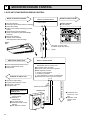
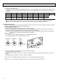
2-1COOL operation
<How to operate>
1 Press POWER ON/OFF button.
2 Press the a button to display “f”.
3 Press the i TEMP button to set the desired temperature.
NOTE: Set temperature changes 1°C when the
or
button is pressed one time.
Cooling 19°C to 30°C
FILTER
CHECK MODE
TEST RUN
4
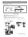
<COOL operation time chart>
Operation starts by
POWER button
ON.
Room temperature
becomes equal to
set temperature.
Room temperature
rises above set
temperature.
Operation stops by
POWER button
OFF.
ON
Thermostat
OFF
ON
Indoor fan
OFF
Auto vane
30°
discharge
position
LOW or HIGH
LOW or HIGH
Initially horizontal
(Changeable by remote controller setting)
30°
discharge
position
3 minutes
ON
Drain pump
(OPTIONAL)
OFF
Booster heater
OFF
Compressor
OFF
ON
OFF
ON
Minimum 3 minutes w1
w1 Even if the room temperature rise above the set temperature during this period, the compressor will not start until this period has ended.
(1) Compressor control
1 3-minute time delay
To prevent overload, the compressor will not start within 3 minutes after stop.
2 The compressor runs when room temperature is higher than set temperature.
The compressor stops when room temperature is equal to or lower than the set temperature.
3 The compressor stops in check mode or during protective functions.
4 Coil frost prevention
To prevent indoor coil frost, the compressor will stop when the indoor coil thermistor (RT2) reads 1°C or below after the
compressor has been continuously operated for at least 16 minutes or more. When the indoor coil temperature rises to
10°C or above, the compressor will start after a 3-minute time delay.
NOTE : By cut off the J-5 (Jumper resistance)on indoor controller board, the start temperature of coil frost prevention
changes from 1°C to -3°C.
27
5 Coil frost protection
When indoor coil temperatuer becomes -15°C or below,coil frost protection will proceed as follows.
<Start condition>
After the compressor has been continuously operated for 3 minutes or more,and the indoor coil temperature has been 15° or below for 3 minutes,the coil frost protection will start.
<Coil frost protection>
Compressor stops for 6 minutes,and then restarts.
lf the start condition is satisfied again during the first 10 minutes of compressor operation, both the indoor and outdoor
units stop,displaying a check code of“P6”on the remote controller.
<Termination conditions>
Coil frost protection is released when the start condition is not satisfied again during the allowance, or when the COOL
mode stops or changes to another mode.
(2) Indoor fan control
Indoor fan speed LOW/HIGH depends on the remote controller setting.
However, if an outdoor unit abnormality is detected, the indoor fan speed will be LOW, regardless of the remote controller
setting.
When the outdoor unit abnormality detection is released and the fan speed returns to the set speed, the quiet cycle control
will work.
(a) Normal control
( i ) Fan speed LOW/HIGH depends on the remote controller setting regardless of the thermostat ON/OFF.
(ii) Fan speed will remain on LOW if an abnormality in outdoor unit is detected. (5 minutes)
When the abnormality detection is released, the fan speed returns to the set speed.
5 minutes
SET
5 minutes
SET
LOW
LOW
OFF
1 Start-up of outdoor unit abnormality detection.
2 Release of outdoor unit abnormality detection.
3 Unit stop due to outdoor unit abnormality
with P8 indication.
NOTE 1 : Fan stops immediately if the unit stops or the check mode is started.
28
(3) Auto vane control
Auto vane position is set to horizontal airflow at the start-up of COOL operation. It can then be changed by the remote controller.
(a) Stop mode (fixed operation)
( i ) At start-up of COOL operation, the auto vane is set to 30 degrees airflow direction.
( ii ) Discharge direction can be changed with
botton.
1 Fan speed : LOW
Horizontal
40°
60°
SWING
40°
60°
SWING
2 Fan speed : HIGH
Horizontal
20°
w Vane angle can be change to upper angle by cutting off the J5-3.(Jumper resistance of indoor units)
(b) SWING mode.
( i ) The vane motor turns ON when the SWING mode is selected.
The vane motor is continuously ON during SWING mode.
<AUTO RETURN>
1 Fan speed : LOW
40
holizontal
AUTO RETURN
60
AUTO RETURN
2 Fan speed : HIGH
holizontal
20
40
60
When 40° degrees or 60° degrees airflow is selected with the LOW fan speed in COOL operation, “AUTO RETURN” will
appear below the temperature display. One hour later, the airflow direction returns to horizontal automatically and “AUTO
RETURN” will disappear. If the airflow direction is set to horizontal during “AUTO RETURN” indication, the time counting
for AUTO RETURN is cancelled.
29
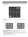
<Auto vane drive>
(a) The auto vane is driven by DC12V motor.
(b) Airflow direction is selected depends on the number of pulse were sended.
(c) Before start driving the auto vane, detect the standard position first, output the number of pulse to each airflow.
(d) The speed of the auto vane drive for both open and close are setted at 200 pulse/sec.
(d) Method of driving the auto vane.
1 Detecting the standard position :
Output 1448 (PCH-2~3),1498 (PCH-4~6)
2 Position setting :
Output the number of pulse indicated no below chart to the closing direction.
The number of pulse outputed after
directing the standard position
Close
Horizontal
Downward A
Downward B
Downward C
PCH-2~3
1448
247
435
624
813
PCH-4~6
1498
318
511
693
817
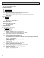
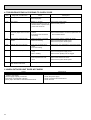
(4) Detecting abnormalities in the outdoor unit
After the compressor has been continuously operated for 3 minutes, if the difference between the indoor coil temperature
and room temperature is out of RANGE C for 1 minute, the indoor fan speed will turn to LOW. Five minutes later, if the difference is still out of RANGE C,the outdoor unit is functioning abnormally. Thus, the compressor stops and check code
“P8” appears on remote controler.
RANGE A : Indoor coil temperature is more than 5 degrees above room temperature.
RANGE B : Indoor coil temperature is within 5 degrees either way of room temperature.
RANGE C : Indoor coil temperature is more than 5 degrees below room tempetature.
Indoor coil temperature
minus room temperature.
(degree)
+5
RANGE A
0
RANGE B
-5
RANGE C
(5) Drain pump control (OPTION)
The drain pump works in COOL or DRY operation. When operation stops or changes to HEAT mode, the drain pump continues to operate for 3 more minutes. The drain pump does not work in check mode.
<Drain sensor>
When both the drain pump and unit are operating, the drain sensor detects the temperature. This temperature tells
whether the drain water level is above or under the drain sensor. If the drain water level rises above the drain sensor due
to a drain pump malfunction, the unit will stop operating in order to prevent drain from overflowing. The check code “P5” on
the remote controller will display this occurrence. When either of the following conditions are satisfied, the drain sensor is
determined to be under water.
● Though the drain sensor has been heated by the drain sensor heater for more than 40 seconds, its temperature rise is
less than 20 degrees.
● The drain sensor temperature is below 63°C.
30
2-2 DRY operation
<How to operate>
1 Press POWER ON/OFF button.
2 Press the a button to display “ e ”.
3 Press the i TEMP button to set the desired temperature.
NOTE: The set temperature changes 1°C when the
button is pressed one time.
Dry 19°C to 30°C.
FILTER
CHECK MODE
TEST RUN
or
4
<DRY operation time chart>
Operation starts by
POWER button
ON.
Room temperature
becomes equal to
set temperature.
Room temperature
rises above set
temperature.
Operation stops by
POWER button
OFF.
ON
Thermostat
OFF
LOW speed
Low speed
ON
Indoor fan
OFF
Initally 35degrees (SW5-3:OFF) or 20degrees (SW5-3:ON) discharge
(Changeable by remote controller setting)
Auto vane
close
close
3 minutes
Drain pump
(OPTIONAL)
ON
OFF
ON
Booster heater OFF
OFF
ON
Compressor
OFF
Minimum 3 minutes w1
w1 Even if the room temperature rises above the set temperature during this period, the compressor will not start until this period has ended.
(1) Compressor control
13-minute time delay
To prevent overload, the compressor will not start within 3 minutes after stop.
2The compressor runs when the room temperature is higher than the set temperature.
The compressor stops when the room temperature is equal to or lower than the set temperature.
3The compressor stops in check mode or during protective functions.
31
4The compressor will not start when the room temperature is below 18:.
The compressor start intermittent operation when the power is turned ON with room temperature above 18;. The compres
sor ON/OFF time depends on the themostat ON/OFF and the following room temperature.
After 3-minute compressor operation.
●If the room temperature thermistor reads above 28: with themostat ON, the compressor will operate for 6 more minutes
and then stop for 3 minutes.
●If the room temperature thermistor reads above 26: ~ 28: with themostat ON, the compressor will operate for 4 more min
utes and then stop for 3 minutes.
●If the room temperature thermistor reads above 24: ~ 26: with themostat ON, the compressor will operate for 2 more min
utes and then stop for 3 minutes.
●If the room temperature thermistor reads below 24: with themostat ON, the compressor will stop for 3 minutes.
●If the thermistat is OFF regaedless of room temperatere, the compressor will stop for 10 minutes.
5Coil frost protection
Coil frost protection in DRY operation is the same as in COOL operation.
6Coil frost protection
Coil frost protection does not operate in DRY operation.
(2) Indoor fan control
The indoor fan runs on LOW speed during compressor operation. The fan speed cannot be changed with the remote controller. Also, the indoor fan does not run during compressor OFF.
(3) Auto vane & drain pump controls
Same as in COOL operation.
(4) Detecting abnormalities in the outdoor unit
An abnormality in the outdoor unit can not be detected in DRY operation.
32
2-3 HEAT operation
<How to operate>
1 Press POWER ON/OFF button.
2 Press the a button to display “ g ”.
3 Press the i TEMP button to set the desired temperature.
NOTE: The set temperature changes 1°C when the
or
button is pressed one time.
Heating 17°C to 28°C
<Display in HEAT operation>
[DEFROST]
The [DEFROST] symbol is only displayed during the defrost
operation.
[STANDBY]
The [STANDBY] symbol is displayed from the heating operation
starts until the heated air begins to blow.
FILTER
CHECK MODE
TEST RUN
4
<HEAT operation time chart>
Operation starts by
POWER button
ON.
Room temperature
becomes equal to
set temperature.
Room temperature
rises above set
temperature.
Operation stops by
POWER button
OFF.
ON
Thermostat
OFF
Extra LOW
1
Extra LOW w 1
LOW
ON
Indoor fan
OFF
Horizontal
Drain pump
(OPTINAL)
Depends on remote
controller setting
Depends on remote
controller setting
close
Horizontal
close
Auto vane
w 1 Changeable by indoor
Jamper resistance
J1-7 and J1-8
LOW or HIGH
LOW or HIGH
OFF
ON
OFF
OFF during
ON
Booster heater OFF
Hot adjustment
{
themostat OFF
hot adjustment
defrosting
Hot adjustment
ON
Compressor
OFF
Minimum 3 minutes w 2
ON
Power ON lamp OFF
From POWER ON until
warm begins to blow
ON
STAND BY lamp OFF
w2 Even if the room temperature rises above the set temperature during this period, the compressor will not start until this period has ended.
33
(1) Compressor control
13-minute time delay
To prevent overload, the compressor will not start within 3 minutes after stop.
2The compressor runs when the room temperature is higher than the set temperature.
The compressor stops when the room temperature is equal to or lower than the set temperature.
3The compressor stops in check mode or during protective functions.
4Overheat protection.
<Start condition>
When the indoor coil thermistor reads 70: or above, the overheat protection will start.
<Overheat protection>
The compressor stops for 6 minutes, and then restarts.
If the start condition is satisfied again within 10 minutes of compressor operation, both the indoor and outdoor units stop,
displaying a check coe of “P6” on the remote controller.
<Termination conditions>
Overheat protection is terminated when the start condition is not satisfied again during the allowance (10-minute
compressor operation), when operation mode changes to other mode, or when thermostat turns OFF.
(2) Indoor fan control
(a) Normal control
(!)The indoor fan runs on EXTRA-LOW speed during the thermostat OFF.
EXTRA-LOW speed can be changed to LOW or HIGH speed by setting the Jumper resistance J1 and J1-8. If the
indoor coil temperature becomes more than 5 degrees below the room temperature during the thermostat OFF, the
indoor fan will stop. After, when the indoor coil temperature becomes within 5 degrees of room temperature, the
indoor fan will run on EXTRA-LOW speed.
(@)Hot adjustment
Hot adjustment is a warm-up for HEAT operation.
<Start conditions>
The hot adjustment works under any of the following conditions.
●HEAT operation starts.
●Defrosting ends.
●Thermostat turns ON.
<Hot adjustment>
Initially, the indoor fan runs on EXTRA-LOW speed. When 5 minutes have passed or the indoor coil temperature
exceeds 35:, the fan speed changes to LOW. Two minutes later, the hot adjustment ends. Then, the fan speed
depends on the remote controller setting.
(#)The indoor fan stops when the indoor coil temperature is within 5 degrees either way of room temperature.
($)To eliminate the remaining heat, the indoor fan runs for the first 1 minute after the booster is turned OFF.
34
(3) Auto vane control
(a) STOP mode (fixed operation)
( i ) The airflow direction at the start-up of HEAT operation is the same as that of the previous operation.
( ii ) The airflow direction can be charged by the remote controller setting.
horizontal
20°
40°
60°
SWING
In the following cases, airflow direction becomes horizontal regardless of the remote controller setting.
1 During the hot adjustment with fan speed at EXTRA-LOW
2 During defrosting with indoor fan OFF
3 During the thermostat OFF
(b) SWING mode
( i ) The vane motor turns ON when the SWING mode is selected.
The vane motor is continuously ON during SWING mode.
( ii ) In the following cases, the airflow direction is horizontal regardless of the remote controller setting.
1 During the hot adjustment with fan speed at EXTRA-LOW
2 During defrosting with indoor fan OFF
3 During thermostat OFF
(4) Booster heater control
When the room temperature is 3 degrees below from the set temperature, the booster heater will turn ON.
When the room temperature is equal to the set temperature, booster heater will turn OFF.
During the hot adjustment, the booster heater will not work.
< Overheat prevention >
When the indoor coil thermistor rises to 60: or above, the booster heater cannot work.
When the indoor coil thermistor falls to 55: or below, the booster heater can work.
(5) Detecting abnormalities in the outdoor unit
When the outdoor unit is determined to be abnormal by the following causes, the compressor will stop and the check code
“ P8 ” will appear on the remote controller display.
1 During compressor ON after hot adjustment
w1 (See the next page)
1 If the difference between the indoor coil temperature and room temperature is in the RANGE B, the indoor fan will
stop.
2 Within 20 minutes after entering RANGE B (except for the first 10 seconds),
a) If the temperature difference enters RANGE A, the hot adjustment stasrts,
b) If the temperature difference is still in RANGE B, the outdoor unit is deemed abnormal.
c) If the temperature difference enters RANGE C, defrosting starts.
Within 20 minutes after entering RANGE C,
●If the temperature difference does not return to RANGE B,the outdoor unit is deemed abnormal.
●If the temperature difference returns to RANGE B, the next 20 minutes is an allowance period. If the difference enter
RANGE A during the allowance, defrosting ends and the hot adjustment starts. If the difference does not enter
RANGE A during the allowance, the outdoor unit is deemed abnormal.
2 During compressor ON in hot adjustment
After 30 minutes of defrosting in hot adjustment, if the temperature difference is still in RANGE C, the outdoor unit is
determined to be abnormal.
3 During compressor OFF
After 20 minutes of thermostat OFF, if the indoor coil thermistor reads -25°C or below, the outdoor unit is determined to
be abnormal.
35
(6) Indoor coil thermistor abnormality detection
An abnormality can be detected during compressor ON, except for the following.
●For the first 30 minutes after the temperature difference between the indoor coil temperature and room temperature
enters the RANGE C.
●When the temperature difference enters the RANGE C until it moves to the RANGE B.
(7) Defrosting operation
After the outdoor unit starts the defrosting operation, when the temperature difference beetween the indoor coil temperature and room temperature gets out of RANGE A and into RANGE B, the indoor unit starts the defrosting mode. After the
outdoor unit stops the defrosting operation, when the temperature difference returns to the RANGE A, the indoor unit stops
the defrosting mode. While the indoor unit is in the defrosting mode, the indoor fan and the booster heater stop.
w1 RANGE A : Indoor coil temperature is more than 5 degrees above room temperataure.
RANGE B : Indoor coil temperature is within 5 degrees either way of room temperature.
RANGE C : Indoor coil temperature is more than 5 degrees below room temperature
Indoor coil temperature
minus room temperature
(degree)
+5
RANGE A
0
RANGE B
-5
36
RANGE C
2-4 AUTO operation (Automatic COOL/HEAT change over operation)
<How to operate>
1 Press POWER ON/OFF button.
2 Press the
button to display “
”
3 Press the
TEMP button to set the desired temperature.
NOTE: The set temperature changes 1°C when the
or
button is pressed one time.
Automatic 19 to 28°C
●“AUTOMATIC” works to change by itself the operation
mode either to cooling or heating according to the room
temperature.
FILTER
CHECK MODE
TEST RUN
4
(1) Initial mode
1 When AUTO operation starts after unit OFF.
● If the room temperature is higher than the set temperature, operation starts in COOL mode.
● If the room temperature is equal to or lower than the set temperature, operation starts HEAT mode.
2 When AUTO operation starts after COOL or HEAT operation, the previous mode continues.
(2) Mode change
1 HEAT mode changes to cool mode when 15 minutes have passed since the room temperature became 2 degrees
above the set temperature.
2 COOL mode changes to HEAT mode when 15 minutes have passed since the room temperature became 2 degrees
below the set temperature.
To:Set temperature (19
(degree)
28
When room temperature becomes 2 degrees above the set temperature,the operation mode can not be changed
for 15 minutes.
)
Mode change (HEAT
COOL)
To + 2
To + 1
To
To - 1
To - 2
15 minutes
Start
COOL mode
HEAT mode
Compressor
Mode change
(COOL HEAT)
15 minutes
Minimum 3 minutes
HEAT mode
ON
OFF
Minimum 3 minutes
(3) Temperature range
AUTO operation is available under the outside air temperatures as follows.
-9
0
10
20
30
40
46
(Outside air temperature)
-5
-8.5
Cooling range
Heating range
37
2-5 Auto vane control
<How to operate>
To change the air flow direction, press
FILTER
CHECK MODE
button.
NOTE: Vane angle can be change to upper angle by cutting off the J5-3.
(Jamper resistance of indoor units)
TEST RUN
4
1
Horizontal
2
20˚
3
40˚
4
60˚
5
swing
Changes by pressing the
Available in COOL operation with fan speed on HIGH or in
HEAT operation.
Unavailable in DRY operation.
If fan speed changes from LOW to HIGH during 20°
downward airflow in COOL mode, the direction
automatically changes to horizontal.
button.
(1) COOL/DRY operation
At the start-up of COOL or DRY operation, the airflow direction in automatically set to horizontal. After, it can be changed
to another direction with
button on the remote controller.
<Auto return>
When 40° or 60° airflow is set with fan speed in LOW, “AUTO RETURN” appears below the room temperature display.
One hour later the direction changes to horizontal degrees, automatically and “AUTO RETURN” disappears.
(2) HEAT operation
At the start-up of HEAT operation, airflow direction depends on the setting of the last operation.
After, it can be changed to another direction with
button. The airflow direction shifts to horizontal regardless of the
remote controller settings under any of the following conditions.
● Thermostat OFF
● Defrosting
● Indoor fan speed EXTRA-LOW in hot adjustment
38
2-6 TIMER operation
<Timer function>
AUTO STOP ·········The air conditioner stops after the set time lapses.
AUTO START ········The air conditioner starts after the set time lapses.
TIMER OFF ··········Timer is not active.
<How to operate>
1. Press POWER ON/OFF button.
FILTER
CHECK MODE
TEST RUN
2. Press “ ” button to select AUTO STOP or AUTO START.
3. Press “
” button to set desired time.
Time setting is in 1 hour units for up to 24 hours.
Each time HOURS button is pressed, set time increases by 1 hour.
When HOURS button is pressed and held, the set time increases
by 1 hour every 0.5 seconds.
4. To cancel the timer operation, press POWER ON/OFF button.
4
<Timer setting example>
OFF
This setting will stop the air conditioner in 8 hours.
With the lapse of time, time display changes in 1 hour units, showing remaining time.
2-7 Test run
<Before test run>
● After installing, wiring, and piping the indoor and outdoor units, check for refrigerant leakage, looseness in power supply or
contorol wiring, and mistaken polarity.
● Use a 500-volt megger to check the resistance between the power supply terminal block and ground to make sure that it is
at least 1.0MΩ.
Attention:
Do not use the air conditioner if resistance is less than 1.0MΩ.
Remote controller
FILTER
1
Turn on main switch,12 hours before proceeding to step 2 to allow
for crankcase heater operation.
2
Push the TEST RUN button twice and indication of TEST RUN will
be shown on the liquid crystal display.
3
Press the
button to display
, COOL/DRY(or HEAT)to
confirm that cool (or warm) air is blown out.
(At heating operation, there may be a short delay before warm air
begins to blow out.)
4
Push
properly.
5
Check the operation of outdoor unit fans.This unit controls the rotation speed and performance capacity of fans.ln some cases,it may
rotate at low speed as the condition of outside air requires and the
speed will be kept unless the performance has become deficient.
Therefore,when the condition of outside air demands,there may be
such cases as the fan stops or rotates reversely.
Please note that these symptoms are not mulfunction.
6
After the check is finished leave the test run mode, push the power
ON/OFF button.
It can also be stopped by pushing the timer MODE button.
CHECK MODE
TEST RUN
4
TEST RUN button
TEST RUN Display
Indoor coil temperature code Display
*The above figure shows the state of TEST
RUN at cooling operation.
button LOW/HIGH to check that the fan speed changes
●When a TEST RUN is started,the timer shall be set to 2 hours. The unit will automatically turn off after 2 hours.
39
(1) Indoor coil temperature code
During the test run, the indoor coil temperature code from 1 to 15 is displayed on the remote controller instead of room
temperature. The code should fall with the lapse of time in normal COOL operation, and should rise in normal HEAT
operation.
Code
Indoor coil
temperature
Code
Indoor coil
temperature
1
-40~1:
9
~45:
2
~10:
10
~50:
3
~15:
11
~55:
4
~20:
12
~60:
5
~25:
13
~70:
6
~30:
14
~90:
7
~35:
15
8
~40:
Thermistor
abnormality
(2) Trouble during test run
● If the unit malfunctions during the test run, refer to section 10 in this manual entitled “TROUBLESHOOTING.”
● When the optional program timer is connected to the conditioner, refer to its operating instructions.
2-8 Emergency operation
When the remote controller or microprocessor malfunctions but all other parts are normal, emergency operation is started
by setting the dipswitch SW3 on the indoor controller board.
<Before emergency operation>
1. Make sure the compressor and the indoor fan are operating normally.
2. Locate the defect with the self-diagnostic function. When the self-diagnostic function indicates “protective function is
working”, release the protective function before starting the emergency operation.
CAUTION: When the self-diagnostic function indicates a check code of “P5” (drain pump malfunction), DO NOT start
the emergency operation because the drain may overflow.
<How to operate>
1. For emergency cooling, set the dipswitch SW3-1 to ON and SW3-2 to OFF.
For emergency heating, set the dipswitch SW3-1,2 to ON.
Emergency
cooling
1
1 ON
2
Emergency
heating
1
2
1.2 ON
Normal
operation
1
2
1-2 OFF
Microcessor board
2. Turn ON the outdoor unit breaker and then ON the indoor unit breaker.
Emergency operation will now start.
3. During emergency operation, the indoor fan operates on high speed, but the swing louvers and the auto vanes do not
operate.
4. To stop emergency operation, turn OFF the indoor unit breaker.
NOTE: The remote controller POWER ON/OFF button can not start/stop emergency operations.
CAUTION: Do not use emergency cooling for more than 10 hours, as the indoor coil may freeze.
40
2-9 Interlock with ventilation system (LOSSNAY)
Mr. SLIM/LOSSNAY interlock operation is available by using the optional parts listed below.
(1) System organization
Relay box (PZ-12RB-E)
Relay box
Mr. SLIM
LOSSNAY
LOSSNAY
Power supply
Mr. SLIM
Power
supply
Remote
controller
LOSSNAY control switch (PZ-05SLB2-E)
Remote display
adapter
(PAC-SA88HA-E)
Remote
controller
LOSSNAY control switch
(PZ-05SLB2-E)
(2) LOSSNAY models connectable to Mr. SLIM are: LGH-15RS-E, LGH-50RS-E
LGH-25RS-E, LGH-80RS-E
LGH-35RS-E, LGH-100RS-E
(3) Reqired parts are:
● Relay box (PZ-12RB-E)…Contact capacity 10A
● Remote display adapter (PAC-SA88HA-E)…An optional part for Mr. SLIM
● LOSSNAY control switch (PZ-05SLB2-E)…For LOSSNAY individual operation
(4) Operation
1LOSSNAY turns ON/OFF according to Mr. SLIM ON/OFF
2While Mr. SLIM is OFF, LOSSNAY individual operation is available by using the LOSSNAY control switch.
When Mr. SLIM turns OFF with the LOSSNAY control switch at ON, LOSSNAY will continue to operate.
(5) Wiring.
1When the LOSSNAY control switch is used
2When the LOSSNAY control switch is not used:
Mr. SLIM
Indoor controller
board
Remote
controller
Power supply
for Mr. SLIM
220 240V AC
Relay box
(PZ-12RB-E)
LOSSNAY
Terminal block
Terminal block
A
Connector
CN51
B
L
N
HIGH
N
GRN
YLW
ORN
RED
BRN
ORN
LOW
RED
10m
Insulation
is needed
Relay box
(PZ-12RB-E)
A
B
Connecting wire
0.13mm 2 or over
Connecting wire
solid wire,
1.6 or 2.0
(field supplied)
YLW
8
ORN
L
RED
N
WHT
HIGH
HIGH
RED
WHT
N
WHT
Mr.SLIM
CN51
12V DC
Circuit
breaker
2
5
RED
DAMPER
7
6
N
4
L
N
Power supply
220 240V AC
ORN
DAMPER
WHT
3
1
Circuit breaker
(field supplied)
L
Power
supply
N
50Hz
220 240V
LOSSNAY
Terminal
block
N
L
ORN
LOW
LOW
PL
HIGH
N HIGH
N
DAMPER
DAMPER
DAMPER
LOSSNAY control switch
(PZ-05SLB 2-E)
RED
WHT
RED
ORN
WHT
NOTE: For further information, refer to the
LOSSNAY technical & service manual.
Junction box
(field supplied)
41
2-10 Dip switch functions
Each figure shows the initial factory setting.
1 On remote controller board
(1) SW17(Address selector)
1 2 3 4 5 6 7 8
ON
OFF
SW17-1~6) For address setting
SW17-7) When two remote controllers are used,this switch sets the controller function.
OFF:The remote controller is set as a main controller.
ON:The remote controller is set as a sub controller.
SW17-8) Switch for system back-up (This switch is unavailable for PLH-GKHA.Keep this switch at OFF.)
OFF:Without back-up
ON:With back-up
(2) SW18 (Function selector)
ON
OFF
1 2 3 4
SW18-1) Switch for timer
OFF:Single day
ON:Timer every day
SW18-2) Switch for filter sign
OFF:Filter sign absent
ON:Filter sign present
SW18-3) Switch for filter sign time setting.
OFF:100Hr ON:2500Hr
SW18-4) Not yet used.
2 On indoor controller board
PCH-2,2.5,3,4,5,6,GKH(S)A1
(1) J1 (Function selector Jumper resistors)
1
J1-4)
J1-5)
J1-6)
J1-7)
J1-8)
J1-9)
J1-10)
42
4
5
6
7
8
9
10
Switch for drain pump
Provided
:The drain pump works in only COOL operation.
Not Provided :The drain pump works in both COOL and HEAT operation.
Switch to change the temperature to start coil frost prevention
Provided
:1°(For all current models)
Not Provided :-3°(For previous special models)
Switch for set temperature adjustment in HEAT mode
During HEAT operation,warm air collects near the ceiling.When the indoor unit is installed near the ceiling,the
temperature read by room temperature thermistor differs from the actual living-space temperature by about 4
degrees. Therefore,the room temperature read by room temperature thermistor must be lowered by 4 degrees.
Provided
:4-degree adjustment
Not Provided :No adjustment
Switch for fan speed during thermostat OFF in HEAT operation
Provided
:EXTRA LOW
Not Provided :LOW
Switch for fan speed during thermostat OFF in HEAT operation
Provided
:EXTRA LOW or LOW(set with SW1-7)
Not Provided :LOW or HIGH(set with remote controller)
Switch for detecting abnormalities in the outdoor unit abnoamality detection
Provided
:When an abnormality occurs,it is detected.
Not Provided :Even if an abnormality occurs,it can not be detected.
Switch for auto restart function
Provided
:This function does not work
Not Provided :This function works.
(2) SW2 (Address selector)
1 2 3 4 5 6
Used insetting the unit-address for group control.
ON
For further information, refer to page 40.
OFF
(3) SW3 (Emergency operation switch)
Normal operation
1 2
ON
OFF
For emergency cooling
1 2
ON
OFF
For emergency heating
1 2
ON
OFF
(4) J5 (Model selector emergency heating)
2
3
4
J5-2) Provided
: For models with heat pump.
Not provided : For models without heat pump.
J5-3) Available
: Vane horizontal angle ...... Normal
Not available : Vane horizontal angle ...... Upper angle
J5-4) This jumper is unavailable for PCH-GKA, keep this.
Single control
Twin control
Triple control
SW6-1
OFF
ON (Twin No.1)
ON (Triple No.1)
SW6-2
OFF
ON (Twin No.2)
ON (Triple No.2)
SW6-3
OFF
OFF
ON (Triple No.3)
SW6-4
OFF
OFF
ON
(5) SW6 (Model selector)
1 2 3 4
ON
OFF
(6) SW7 (Model selector)
SW7-1,7-3,7-4) : Capacity setting
1 2 3 4
1 2 3 4
ON
OFF
PCH-2
ON
OFF
PCH-2.5
ON
OFF
PCH-3
ON
OFF
PCH-4
ON
OFF
PCH-5
ON
OFF
PCH-6
SW7-2) Voltage change
ON : 240V
OFF : 220V
(7) J9 (Model selector)
J9-1) Provided
J9-2) Provided
2
}
PCH-GKHA
3
43
2-11 INDOOR FAN CONTROL
Each figure shows the initial factory setting.
(1) Fan motor max. rotational frequncy for PCH-GKHA
(2) Indoor fan relay output
(a) During fan ON
The indoor fan relay turns ON. One second later, the phase control will start.
(a) During fan OFF
The phase control turns OFF. One second later, the indoor fan relay will turn OFF.
Service Ref.
PCH-2GKHA1
PCH-2.5GKHA1
PCH-3GKHA1
PCH-4GKHSA1
PCH-5GKHSA1
PCH-6GKHSA1
44
Voltage
(V)
220
230
240
220
230
240
220
230
240
220
250
240
220
230
240
220
230
240
100% rotational
frequency (rpm)
15Hz
1370
1380
1390
1350
1360
1370
1350
1360
1370
1150
1160
1170
1150
1170
1190
1160
1180
1200
3. OUTDOOR UNIT CONTROL
3-1 Outdoor fan control
The rotational frequency of outdoor fan is phase-controlled according to the outdoor coil temperature. This control allows the
cooling operation even with the low outside-air temperature and the heating operation even with the high outside-air temperature.
3-2 Outdoor unit control
The outdoor unit turns ON/OFF the cooling/heating operation according to orders given from the indoor unit.
3-3 Protective functions
1 If an reversed-phase, an open phase, or an indoor controller abnormality is detected, the outdoor unit will stop operation
and the check mode will start. (For the check mode details, see page 52.)
2 If a protective function works, the compressor will stop running. Three minutes later, the compressor will restart. If the protective function works again, the compressor will stop running and the check mode will start.
3 The protective function is memorized.
4 The memory is cleared when the POWER ON/OFF button on the remote controller is turned OFF. However, the check
mode dispaly continues until the outdoor unit receives the “operation ON” command from the indoor unit.
3-4 COOL/HEAT operation time chart
Operation starts by
P O W E R b u t t o n ON.
Room temperature
becomes equal to set
temperature.
Room temperature
becomes different from
set temperature.
Operation stops by
POWER button OFF.
ON
Thermostat
OFF
ON
Compressor
OFF
60 minutes
Crankcase heater
(with jumper wire
J3)
Crankcase heater
(without jumper
wire J3)
4-way valve
(COOL)
4-way valve
(HEAT)
60 minutes
ON
OFF
ON
60 minutes 60 minutes 60 minutes 60 minutes 60 minutes Repeats 60-minute
ON/OFF
OFF
ON
OFF
10 minutes
10 minutes 1
3 minutes
3 minutes
ON
OFF
ON
Bypass valve
OFF
ON
Outdoor fan
OFF
w1 If compressor restarts within 10 minutes, 4-way valve remains ON.
45
3-5 Defrosting in HEAT mode
<Defrosting time chart>
Defrosting
stops.
Defrosting
starts.
Indoor unit
ON
Indoor fan
OFF
Auto vane
35degrees(SW5-3 OFF)or 20degrees(SW5-3:ON)discharge direction
ON
OFF
Set direction
(Remote controller still displays set direction.)
Set direction
Outdoor unit
ON
4-way valve
OFF
Bypass valve
ON
OFF
Outdoor fan
ON
OFF
Compressor
ON
OFF
(1) Start conditions
A. When all of the following conditions are satisfied, defrosting will start. However, when the bypass valve turns OFF,
defrosting starts 10 minutes later.
(a) More than seven minutes have passed since the compressor start-up.
(b) The outdoor coil thermistor reads -5°C or below.
(c) The outdoor fan motor output step is 100%
(d) Total time of compressor operation exceeds 30 minutes, and the outdoor coil temperature has fallen by 8 degrees or
more in comparison with that of 10 minutes after the compressor start-up.
NOTE: The outdoor coil temperature of 10 minutes after the compressor start-up is memorized until the defrosting
operation has ended.
B. When all of the following conditions are satisfied, defrosting will start.
(a) ~ (c) The same as above (a) ~ (c) in item A
(d) Total time of compressor operation exceeds “defrost interval”.
Further information on the defrost interval is described in (3).
C. After the total time of compressor operation exceeds the defrost interval, the thermostat repeats ON/OFF three times.
Two minutes after the fourth “ON” of the thermostat, if the outdoor coil thermistor reads -5°C or below and the fan output output is 100%, defrosting will start.
NOTE: The count of the thermostat ON/OFF is cleared by the compressor-OFF command or defrosting start-up.
(2) During defrosting
● Even if the thermostat turns OFF, defrosting continues.
● The 4-way valve, bypass valve, outdoor fan, and indoor fan are OFF.
46
(3) Defrost interval
The defrost interval time is determined as follows.
● Initial defrost interval is 50 minutes.
● The defrost interval after defrosting depends on the preceding defrosting time as shown below.
Defrosting operation time
3 minutes or below
Next defrost interval
120 minutes
3 to 7 minutes
80 minutes
7 to 10 minutes
60 minutes
10 to 15 minutes
40 minutes
15 minutes (Maximum)
30 minutes
NOTE1:If the unit stops during defrosting , the next defrost interval will be 50 minutes.
NOTE2:If a protection function works for the first time during defrosting, the compressor will stop.
After a 3-minute time delay, defrosting will restart. In this case, a 3-minute time delay is included with the defrosting
time.
If the protection function works for the second time, the unit stops operation and displays the check code.
The next defrost interval will be 30 mimutes.
NOTE3:When the defrosting has ended, the total time of the compressor operation is cleard.
(4) Termination conditions
Defrosting finishes when any of the following conditions are satisfied.
1Defrosting has continued for 15 munites.
2Outdoor coil thermistor reads 22°C or above for the first 75 seconds after defrosting start-up.
3Outdoor coil thermistor reads 8°C or above after the 75-second defrosting.
4Power ON/OFF button is turned OFF during defrosting.
3-6 Actuators
(1) Bypass valve control
<Cooling mode>
1When the unit stops due to the coil frost prevention, the bypass valve turns ON. When one hour ahs passed since the
compressor stopped, the bypass valve returns to OFF.
2When the compressor operates with the bypass valve at ON for more than 30 minutes, the bypass valve turns OFF.
3When the compressor stops with the bypass valve at OFF, the bypass valve turns ON and remains ON for three minutes.
<Heating mode>
1When the unit starts for the first time after the circuit breaker has been turned ON, or when it starts after the compressor OFF of 30 minutes or more, if the outdoor coil thermistor reads 12°C or more, the bypass valve turns ON.
2When the high pressure switch (63H1) works, the bypass valve turns ON.
3When the bypass has been ON for 30 minutes:
● If the high pressure switch has already returned, the bypass valve turns to OFF.
● If not, the fan output step keeps 70 for three minutes. Meanwhile, if the high pressure switch returns, the bypass
valve turns OFF. Otherwise the normal fan control starts.
4When the operation mode changes or stops, the bypass valve turns ON and remains ON for three minutes.
<Defrosting operation>
1The bypass valve is OFF.
(2) Crankcase heater control
1With jumper wire J3
The crankcase heater is ON from when the power is turned ON until the compressor starts, and then turns ON one
hour after the compressor stops.
2Without jumper wire J3
The crankcase heater is ON from when the power is turned ON until the compressor starts, and repeats 1-hour ON
and 1-hour OFF.
47
3-7 Service functions
(1) Compulsory defrositng
1When all of the following conditions are satisfied, pressing SW2 starts the compulsory defrosting.
● During HEAT mode
● The compressor is ON.
● The outdoor coil temperature is being displayed by LED. (Outdoor controller board dip switch SW3-1 : OFF, SW3-2 :
ON)
● The outdoor coil thermistor reads 8°C or below.
2The operation state and the termination conditions of the compulsory defrosting are the same as those of the normal
defrosting. As an exception, the defrost interval after the defrosting completion is 50 minutes.
(2) Fixed fan-output
While the compressor is operating (exept during defrosting) and the fan output step is indicated by LED, pressing SW2
fixes the fan output. The fixed fan-output can be released when any of the following conditions are satisfied.
1SW2 is pressed again.
2SW3 setting is changed.
3The compressor stops.
4Defrosting operation starts.
(3) Function of switches on the outdoor controller board
SW1: Clears the check code memory (push-button switch)
SW2: Switches the output state indication and the check code display (push-button switch)
SW3-1,2: Switches the output state indication items (dip swtich)
For further information, refer to page 47.
(4) 100% fan output
Fan output is fixed to 100% by shorting the connector CN22. However, the fan stops during compressor OFF or defrosting.
Open-circuit of CN22 restarts the normal fan control.
(5) Time shorterning
Short circuit of the connector CN21 shortens the time as follows
1Fan control period: 30 seconds → 3 seconds
2Three-minutes time delay function : 3 minites → 3 seconds
3Max. time of defrosting : 15 minites → 15 seconds
4Defrost interval : 30 ~ 120 minutes → 3 ~ 12 seconds
5Compressor ON/OFF time for bypass valve ON/OFF : 30 minutes → 3 seconds
6Compressor ON time to start other functions : x minutes → x seconds
7Crankcase heater operation : 1 hour → 6 seconds
48
10
TROUBLESHOOTING
1.TROUBLES IN TEST RUN
Symptom
Cause
Check points
The display “CENTRALLY
CONTROLLED” on remote
controller dose not disappear.
1) Wrong address setting of remote controller/indoor controller board.
2) Timer adapter is connected to the
remote controller.
3) Singnal transmission error between
indoor unit and remote controller.
1) Check the address setting of remote controller
and indoor controller.
2) Make sure the timer adapter is used correctly.
3) 1 Turn another remote controller’s DIP SW177 ON to make it sub controller.
2 Connect the sub controller to the unit, and
turn circuit breaker ON.
● If the display “centrally controlled” disappears, replace the original remote controller.
● If the display remains the same, replace the
indoor controller board.
When remote controller
POWER button is turned
ON, the check code
“EO”appears.
1) Signal transmission error between
indoor unit and remote controller
1) 1 Connect a sub remote controller.
2 Turn circuit breaker ON.
If the display “centrally controlled” remains,
replace the indoor controller board.
3 If the display disappears, turn the remote
controller POWER button ON and check as
follows.
Remote controller
Sub remote controller
1 Operating Display
EO Display
2 Operating Display
Operating Display
3 No Display
EO Display
4 No Display
Operating Display
Malfunction
Malfunction of
indoor Unit
Malfunction of
Remote controller
Malfunction of
indoor Unit and
Remote Controller
Malfunction of
Remote controller
When remote controller
POWER button is turned
ON, operating display
appears, but disappears
soon.
1) Short circuit of indoor/outdoor connecting wire
2) Short circuit of transmission wire.
3) Short circuit of drain sensor heater circuit.
4) Wrong operation of remote controller
due to noise wave emitted by other
appliances.
1), 2) Check the wire
3) Measure the resistance of the drain sensor
connector CN50 1 ~ 3. Normal resistance
should be 82Ω.
4) Turn the circuit breaker OFF, and then turn
ON.
If the remote controller remains abnormal,
despite the above measures, replace the indoor
controller board.
Despite turning POWER
button ON, the remote
controller display does not
appear.
1) Damaged remote controller.
2) Short circuit of transmission wire.
3) Bad contact of indoor CN40.
4) CN40 is attached to a sub unit.
5) Damaged transformer.
6) Bad contact of CN40.
7) Blown fuse.
8) Circuit breaker OFF.
1) Measure the voltage between terminals of
remote controller. If no voltage, remove the
terminals and measure the voltage between
wires. If the voltage is between 6VDC and
12V, replace the remote controller.
2) ~ 8) Check each point.
If it is not defective, replace the indoor
controller board.
49
2. SELF DIAGNOSTIC FUNCTION WITH REMOTE CONTROLLER
2-1 When malfunction occurs during operation
When a malfunction occurs, the indoor and outdoor units stop and the malfunction is displayed on the LCD of the remote controller.
(1) ON the set temperature display part, “CHECK” appears, and the unit
CHECK mode
address and the check code are diplayed alternately at one-second
intervals. (Check mode)
Example
CHECK
Altenately
displayed
FILTER
CHECK
CHECK MODE
TEST RUN
°C
Unit address
°C
Check code
(2) When one remote controller controls several units in the group control, the LCD shows the unit address and check code of the first malfunctioning unit.
(3) To cancel the check mode, press the ON/OFF button. In remote
ON/OFF control, press the remote ON/OFF switch. In centralized
control, turn OFF the ON/OFF button of centralized controller.
4
NOTE: The latest check code is memorized, even if the check mode is cancelled by the way mentioned above. It takes
60 seconds maximum to display the memorized check code.
2-2 How to use the self diagnostic function for service
A. For normal control with one unit and one remote controller
(1) Pressing the
CHECK. button on the remote controller twice starts the self diagnostic function.
(2) During the self diagnostic function, “CHECK” appears at two positions on the remote controller display. Then, at least
10 seconds later, the unit address and the check code is alternately displayed at one-second intervals.
(3) Check and repair the unit according to the check code. (Refer to the next page.)
2-3 For group control using one remote controller
(1) Press the
TEMP. or
TEMP. button on the remote controller to advance or go back to the unit address.
Each time
TEMP. button is pressed, the unit address advances by one. Each time
TEMP. button is
pressed, the unit address goes back by one.
The check code and the unit address, appear alternately.
(2) The check code “U8” means no malfunction has occurred since installation.
The check code “EO” means the following conditions:
● The unit address displayed on the remote controller does not apply to any unit.
● Power is not supplied to the unit.
● Signal transmitting/receiving circuit is abnormal.
(3) Check and repair the unit according to the check code. (Refer to the next page.)
50
Check
Diagnosis of malfunction
Cause
Check points
code
EO
Signal transmitting/receiving During individual unit control
1) Check the transmission wire.
error
1) Bad contact of transmission
2) Check with another remote controller. If “EO” is
(Indoor controller does not
wire
still indicated, replace the indoor controller
respond to remote controller 2) Signal transmitting/receiving cirboard.
signal.)
cuit is abnormal.
If other check code appears. replace the original remote controller.
P1
Abnormality of room temper- 1) Bad contact of thermistor
ature thermistor (RT1)
2) Damaged thermistor
1) Check the thermistor.
2) Measure the resistance of the thermistor.
Normal resistance should be as follows.
0 C ···15kΩ
30 C·····4.3kΩ
10 C······9.6kΩ 40 C ·····3.0kΩ
20 C······6.3kΩ
If the resistance is normal, replace the indoor
controller board.
P2
Abnormality of indoor coil
thermistor (RT2)
P3
Signal transmission error
(Remote controller does not
respond to indoor controller
signal.)
1) Bad contact of transmission
1) Check the transmission wire.
wire
2) Check with another remote controller.
2) Signal transmitting/receiving cirIf “P3” is still indicated, replace the indoor
cuit is abnormal.
board.
3) Wrong operation due to noise
If other check code appears, replace the origiwave emitted by other applinal remote controller.
ances
3) Short-circuit between 1 and 2 of CN40 and
attach CN40 to the following units.
● Second unit in twin control
● Second and third units in triple control
● Sub units in group control
P4
Abnormality of drain sensor
1) Bad contact of transmission
wire
2) Damaged thermistor
1) Check the connector.
2) Measure the resistance of the thermistor 4 ~
5.
As for the normal resistance, refer to the case
of P1.
If the resistance is normal, replace the indoor controller board.
P5
Malfunction of drain pump
1) Malfunction of drain pump
2) Damaged drain sensor
1) Check the drain pump.
2) ● Check the drain sensor.
● Check the drain sensor heater. Normal resistance should be 82Ω.
If the resistance is normal, replace the indoor controller board.
P6
Coil frost protection is working.
1) Short cycle of air cycle
2) Dirty air filter
3) Damaged fan
4) Abnormal refrigerant
1)
2)
3)
4)
P7
System error
1) Wrong address-setting
1)
2) Signal transmitting/receiving cir- 2)
cuit of remote controller is
abnormal.
3) Wrong SW6-setting
3)
Check the address-setting.
Check with another remote controller. If check
code other than “P7” appears, replace the original remote controller.
Check SW6 setting.
P8
Abnormality in outdoor unit
1) Wrong wiring of indoor/outdoor
connecting wire
2) Reversed phase
3) Protection device is working
4) Damaged outdoor coil thermistor
Check the indoor/outdoor connecting wire.
Change the connection of electric wiring.
Check the protection device.
Measure the resistance of the outdoor coil thermistor. If the resistance is normal, replace the
outdoor controller board.
1)
2)
3)
4)
Clear obstructions from the air cycle.
Clean the air filter
Check the fan.
Check the refrigerant temperature.
51
3. SERVICE DATA INDICATION BY SWITCHES ON OUTDOOR CONTROLLER BOARD
Setting dip switchs SW2 and SW3 on the outdoor controller board enables LED to show the output state and check code.
Output state is shown by LED lighting, and check code by blinking.
SW1 : Turning SW1 ON clears the check code. If SW1 is turned ON while the check code is blinking , the indication
changes to output state indication.
NOTE : SW1 is usually available independant of SW3 setting. As an exception, when the check code shows a
reversed phase or an open phase during the power-on-reset state, SW1 is not available.
SW2 : SW2 is turned ON by pressing, and OFF by releasing.
When SW3-1 and SW3-2 are OFF, pressing SW2 changes indication between output state and check code
alternately.
When SW2 is turned On with SW3-1 OFF and SW3-2 ON, the compulsory defrosting starts.
SW3 : Output state indication items depend on the combination of SW3-1 ON/OFF and SW3-2 ON/OFF.
Changed alternately by pressing SW2.
Check code
Output state
Outdoor coil
temperature
(bit)
Fan Output
step
(bit)
Total time of
compressor
operation(Hr)
SW3-1
OFF
OFF
OFF
ON
ON
SW3-2
OFF
OFF
OFF
ON
ON
52
Lighting
LED
Blinking
LD1
Reversed phase
Compressor ON command
from indoor controller
1
1
256
LD2
Open phase
Heating operation command
from indoor controller
2
2
512
LD3
Outdoor coil thermistor is
abnormal
During 63H1 function
4
4
1024
LD4
63H2 function
Compressor ON
8
8
2048
LD5
51C function
Outdoor fan ON
16
16
4096
LD6
26C function
4-way valve ON
32
32
8192
LD7
Overheat protection
Bypass valve ON ❊
64
64
16384
LD8
Input circuit on controller
board is abnormal
Crankcase heater ON
128
128
32768
3-1 Outdoor coil temperature
To obtain data on the outdoor coil temperature, add the number of bits of lighting LEDs, and see the graph below to find
the temperature.
C
100
(Short 238 bits)
80
60
Temperature
40
20
0
-20
-40 (Open 8 bits)
0
50
100
150
200
255
Number of bits
3-2 Fan output step
To obtain data on the fan output step, add the number of bits of lighting LEDs, and see the graph below to find the fan
rotational frequency.
1PUH-2/4K type
2PUH-2.5/3/5/6K type
Type
<50Hz>
Fan rotational frequency (rpm)
Fan rotational frequency (rpm)
<50Hz>
800
600
400
200
0
50
100
150
200
Fan output step (bit)
250
Type
800
600
400
200
0
50
100
150
200
250
Fan output step (bit)
3-3 Total time of compressor operation
Compressor operation time is indicated in 256 hour units. To obtain the compressor operation time, add the hours of lighting LEDs. During the compressor operation time indication, SW2 is not available.
3-4 Check code indication
● When a protection function works for the first time during operation, the operation stops and restarts after the 3-minutes
time delay mode. When the protection function works again, the operation stops. (Check mode) When both SW3-1 and
SW3-2 are OFF, the check code is indicated.
● If the outdoor controller board receives the compressor ON command from the indoor controller board during check
mode the indication changes to output state indication.
● By pressing SW2 duirng normal operation. operation will continue.
● The latest check code is indicated.
53
4. TROUBLESHOOTING ACCORDING TO CHECK CODE
Blinking
Diagnosis of malfunction
LED
LD1 Reversed phase
Cause
Check point
Phases L1, L2, and L3 are con- Check the power supply connection.
nected improperly.
LD2
Open phase
LD3
Outdoor coil thermistor is
● Outdoor coil thermistor is
abnormal. (Open circuit or short
broken.
circuit)
● Thermistor was connected
incorrectly.
LD4
High pressure switch (63H2)
function
● 62H2 was badly connected.
● 63H2 was working.
● Check 63H2 and the outdoor fan motor.
● Check if refrigerant supply is low.
● Check if air cycle is short-cycled.
LD5
Thermal relay (51C) function
● 51C was connected incorrectly.
● 51C was working.
● Check 51C, the compressor, and power supply.
LD6
Thermal switch (26C) function.
● 26C was connected incorrectly.
● 26C is working.
● Check 26C.
● Check if refrigerant supply is low.
● Check if the capillary tube is clogged.
LD7
Over heat protection
● The thermistor is broken.
● Coil temperature is over
67°C.
● Measure the resistance of the thermistor.
● Check the outdoor fan motor.
● Check if air cycle is short-cycled.
LD8
Input circuit of outdoor controller board is abnormal.
● Pulse input is abnormal.
● Replace the outdoor controller board.
● Phase L2 is open.
● Check the power supply.
● Contact of protector, such as ● Check each protector.
thermal switch, opened when
power was turned on.
● Measure the resistance of the thermistor.
● Check the thermistor. If normal, replace the outdoor controller board.
5. WHEN OUTDOOR UNIT DOES NOT WORK
1)
2)
3)
4)
54
Cause
Indoor/outdoor connecting wires are poorly connected.
(Refer to next page.)
Power supply is poorly connected.
Connector or transformer is broken.
Fuse (6A) in the outdoor controller board is blown.
Check points
1) Check the connecting wires.
2) Check the power supply.
3) Check connectors and transformers.
4) Check the fuse.
6. WRONG WIRING ON SITE
6-1 Between remote controller and indoor unit
If the wire is disconnected between the remote controller and the indoor unit, nothing is displayed on the remote controller
when the POWER button is pressed. The beep sound will also not be heard.
6-2 Phenomenon due to wrong wiring between indoor and outdoor units
Wrong wiring
Mode Thermostat
Indoor
Outdoor
1
1
2
2
3
3
OFF
COOL
ON
OFF
HEAT
Indoor
Outdoor
1
1
2
2
3
3
Outdoor
1
1
2
2
3
3
Outdoor
1
1
2
2
3
3
OFF
Outdoor unit stops.
ON
Operation stops. 9 minutes later, check code “P8” appears on
remote controller display.
OFF
Operation stops.
ON
Operation stops. 27 minutes later, check code “P8” appears on
remote controller display.
OFF
Outdoor unit stops.
ON
Operation stops. 9 minutes later, check code “P8” appears on
remote controller display.
OFF
Operation stops.
ON
Operation stops. 27 minutes later, check code “P8” appears on
remote controller display.
OFF
Outdoor unit stops.
ON
Operation stops. 9 minutes later, check code “P8” appears on
remote controller display.
OFF
Operation stops.
ON
Operation stops, 27 minutes later, check code “P8” appears on
remote controller display.
OFF
Outdoor unit stops.
ON
Operation stops. 9 minutes later, check code “P8” appears on
remote controller display.
OFF
Operation stops.
ON
Operation stops. 27 minutes later, check “P8” appears on remote
controller display.
OFF
Operation stops.
ON
Operation stops. 9 minutes later, check code “P8” appears on
remote controller display.
OFF
Operation stops. 4-way valve turns OFF.
ON
27 minutes later, check code “P8” appears on remote controller
display.
COOL
COOL
COOL
HEAT
Indoor
Outdoor
1
1
2
2
3
3
COOL
HEAT
Disconnection between 1 and 1 or 2
and 2.
COOL
HEAT
Disconnection between 3 and 3.
COOL
4-Way valve turns ON. 9 minutes later, check code “P8” appears
on remote controller display.
Cooling operation. Several minutes later, check code “P8” appears
on remote controller display.
Normal operation.
HEAT
Indoor
Operation stops.
ON
HEAT
Indoor
Phenomenon
–
Normal operation.
OFF
Operation stops. 4-way valve turns ON.
ON
Operation stops. 27 minutes later check code “P8” appears on
remote controller display.
HEAT
55
7. OTHER TROUBLES AND CAUSES
Vanes do not work.
Vane motor does not work.
Vane motor is damaged.
Connector is poorly connected.
Vane motor is poorly assembled.
Indoor controller board is damaged.
Unit stops after 5 to
20 seconds operation
Air discharge display
is OFF and
button
does not operate.
In this case, remote
controller is normal.
Refer to check code on remote controller display.
See page 51.
Protection function is working.
Indoor controller board
deems the auto vanes
are not attached to the
unit.
Horizontal anlgle can
not be detected.
Indoor controller is
damaged.
Dip switch setting is
wrong.
Indoor controller is
damaged.
Vane motor is
damaged.
Auto vane is wired after
power is turned to ON.
Power ON/OFF button
is not available.
Beep sound is heard,
but display is turned
OFF.
Beep sound is not heard,
and display remains
OFF.
Vane motor is damaged.
Poorly connected
Disconnected
Indoor/outdoor connecting wire is connected
incorrectly.
Indoor/outdoor connecting wire shorts.
Compressor protector is
damaged.
Deicer is broken.
Remote controller is
damaged.
Transmission wire is
poorly connected
“CENTRALLY CONTROLLED” is displayed.
Transmission wire is
damaged.
Connector is poorly
connected.
Indoor terminal block is
poorly connected.
Remote controller terminal block is poorly
connected.
8. MR. SLIM/LOSSNAY INTERLOCK OPERATION
<Symptoms that are not malfunctions>
If any of the following symptoms occur, they are not malfunctions.
Symptom
Cause
LOSSNAY control switch does not work.
LOSSNAY control switch can not work during interlock operation.
LOSSNAY control switch is effective only while Mr. SLIM is not
operating.
LOSSNAY air speed can not be controlled in interlock operation.
LOSSNAY fan speed is fixed to HIGH during interlock operation.
LOSSNAY fan speed LOW/HIGH can be switched only during
LOSSNAY individual operation with the LOSSNAY contorl
switch.
For LOSSNAY, troubleshooting refer to the LOSSNAY technical & service manual.
56
11
DISASSEMBLY PROCEDURE
PCH-3GKHA1
OPERATING PROCEDURE
1. Removing the air intake grill
(1) Slide the intake grill holding knobs (at two locations) backward to open the intake grill.
(2) When the intake grill left open, push the stoppers on the
rear hinges (at two locations) to pull out the intake grill.
PHOTOS&ILLUSTRATIONS
Figure 1
Intake grill
slide
Intake grill
Holding knobs
Hinges
Pull out the intake grill
2. Removing the electrical box
(1) Remove the air intake grill.
(2) Remove the screw from the beam and remove the beam.
(3) Remove the screws from the electrical cover, and
remove the electrical cover.
(4) Disconnectors including CN6V and CN21.
(5) Remove the screws from the electrical box and pull out
the electrical box.
<Electrical parts in the electrical box>
Terminal block (for power supply)
Terminal block (for in/outdoor connecting wire)
Terminal block (for remote controller)
Fan motor capacitor
Indoor control board
Relay
Transformer
Figure 2
Beam
Slide to the left
Clamp
Screw(electrical cover)
Electrical cover
Screw(electrical box)
Photo 1
Fan motor
capacitor
Relay
Transformer
Indoor
control
board
Terminal
block
Terminal
(remote control)
block
(power suppy)
Terminal
block
(in/out conncting)
57
OPERATING PROCEDURE
3. Removing the fan motor
(1) Remove the intake grill.
(2) Disconnect the fan motor connector.
(3) Unscrew screws for removing the motor guard.
(4) Unscrew screws for removing the fan guard.
(5) Remove the screw for removing the motor support at both
left and right side.
(6) Loosen the set screws at the fan motor side of the connecting joint.
(7) Slide the fan motor to the left side and pull it out.
PHOTOS&ILLUSTRATIONS
Photo 2
Motor gurd
Screws
Motor
Set screws
Motor support
4. Removing the sirocco fan
(1) Remove the air intake grill.
(2) Remove 1 beam.
(3) Unscrew screws for removing the motor guard.
(4) Unscrew screws for removing the fan guard.
(5) Remove the lower casing while pressing the stoppers at
upper side of the casing.
(6) Loosen the set screws at the connecting joint.
(7) Remove the sirocco fan and shaft together by sliding the
shaft to the left.
Connecting joint
Photo 3
Fan guard
Motor guard
(Note)
Make sure that the upper side casing is snaped to the fan
plate securely with catch.
Sirocco fan
Motor
Casing
Bearing
Connecting joint
5. Removing the side panel
(1) Remove the air intake grill.
(2) Remove the screw from the side panel, and remove the
side panel by sliding the panel to the front.
Figure 2
Side panel
Sliding the pare
to the front
Screw
58
OPERATING PROCEDURE
6. Removing the vane motor
(1) Remove the air intake grill.
(2) Remove the left side panel.
(3) Remove the relay connector of vane motor.
(4) Remove the electrical box.
(5) Remove the screws of vane motor, then remove vane
motor.
(Note)
Connect the lead wires and connectors properly and place
them in the proper position so that the wires are not pinched
by other parts.
PHOTOS
Photo 4
Screw
Relay connector of
the pipe thermistor
Check
panel
Left side
panel
Photo 5
Hold
7. Removing the Indoor coil thermistor
(1) Remove the air intake grill.
(2) Remove the right side panel.
(3) Remove the relay connector of the pipe thermistor.
(4) Remove the screw, and remove the check panel.
(5) Extract the indoor coil thermistor from the holder.
<Caution for the installation>
There is a possibility for the short circuit when connector gets
wet by water through the thermistor lead wire.
Therefore, lead wire of the indoor coil thermistor should be
traped as shown in the photo 5.
Indoor coil thermistor
Photo 6
Trap
Screw
Relay connector of
the vane motor
Vane motor
7. Removing the Under panel
(1) Remove the air intake grill.
(2) Remove the beam.
(3) Remove the side panel (right and left).
(4) Unscrew the screws of the under panel, then remove the
under panel.
w Weight of the under panel : app. 2kg.
Photo 7
Screw
Under panel
59
OPERATING PROCEDURE
9. Removing the drain pan (option)
(1) Remove the air intake grill.
(2) Remove the beam.
(3) Remove the side panel (right and left).
(4) Remove the under panel. Remove the screws of the right
and left side drain pan.
(5) Remove the insulation in center of the drain pan, and
after removing the screw, remove the drain pan.
PHOTOS
Photo 8
(Note)
Please aware that there might be drain left in the drain pan
when you remove the drain pump (option).
Screw
10. Removing the guide vane
(1) Remove the intake grill.
(2) Remove the beam.
(3) Remove the side panel (right and left).
(4) Remove the under panel.
(5) Remove the drain pan.
(6) Remove the screw from the guide vane, then remove the
guide vane.
Drain pan
Screw
Photo 9
Drain pan
11. Removing the Auto vane
(1) Remove the intake grill.
(2) Remove the left side panel.
(3) Remove the left side box.
(4) Remove the under panel.
(5) Remove the screw from the auto vane.
(6) Slide the auto vane to the right side and pull the auto vane
out.
Screw
(Insulation)
Screw
Guide vane
Photo 10
Screw
Auto vane
60
OPERATING PROCEDURE
12. Removing the support heater.
(1) Remove the air intake grill.
(2) Remove the beam.
(3) Remove the side panel (right and left).
(4) Remove the relay connector for the pipe thermistor.
(5) Remove the under panel.
(6) Remove the drain pan.
(7) Remove the screw from the pipe cover, and remove the
pipe cover.
(8) Remove the screw from the pipe support, and remove the
pipe fixed support.
PHOTOS
Photo 11
Screws
Clamp
Service
panel
Connector
(heater)
Electrical
box
13. Removing the heat exchanger.
(1) Remove the air intake grill.
(2) Remove the beam.
(3) Remove the side panel (right and left).
(4) Disconnect the relay connector.
(5) Remove the under panel.
(6) Remove the drain pan.
(7) Unscrew the screw of the pipe cover, and remove the
pipe cover.
(8) Unscrew the screw of the pipe support, and remove the
pipe support.
(9) Unscrew the screw of the heat exchanger, and remove
the heat exchanger.
Remove the heat exchanger with care. Since this is quite
heavy, removing work should be done with more than 2
people.
wWeight of heat exchanger : App. 5.3kg
Photo 12
Pipe
support
Screws
Pipe cover
Screws
Heat
exchanger
61
12
PARTS LIST
STRUCTURAL PART
PCH-2GKHA
PCH-2GKHA1
2
19 13 15
4
12
16
28
10
24
11
5
23
17
14
7
18
8
1
9
62
6
27
3
20
26
25
Part numbers that are circled are not shown in the figure
Q'ty / set
No.
Parts No.
Parts Name
Specifications
PCH-2
Remarks
(Drawing No.)
GKHA, GKHA1
1
R01 17J 661 RIGHT SIDE PANEL
1
2
R01 17J 662 LEFT SIDE PANEL
1
3
R01 17J 669 UNDER PANEL
1
4
R01 17J 676 REAR PANEL
1
5
R01 17J 500 L.L. FILTER
1
6
R01 18J 500 L.L. FILTER
1
7
R01 17J 691 GRILLE ASSY
1
8
R01 18J 691 GRILLE ASSY
1
9
R01 17J 054 GRILLE CATCH
4
10 R01 17J 651 FRONT PANEL
1
11 R01 17J 085 GUIDE VANE ASSY-6R.
1
12 R01 18J 086 GUIDE VANE ASSY-6L.
1
13 R01 29J 223 VANE MOTOR
1
14 R01 17J 067 RIGHT SIDE BOX
1
15 R01 17J 068 LEFT SIDE BOX
1
16 R01 17J 002 AUTO VANE
1
17 R01 17J 061 GRILLE HINGE
4
18 R01 17J 808 RIGHT LEG
1
19 R01 17J 809 LEFT LEG
1
20 R01 17J 070 WIRELESS BOARD CASE
1
21 R01 17J 523 JOINT SOCKET
1
22 R01 17J 072 DRAIN HOSE COVER
1
23 R01 18J 665 SIDE PLATE-R.
1
24 R01 17J 666 SIDE PLATE-L.
1
25 R01 17J 668 SERVICE PANEL
1
Wiring RecomDiagram mended
Symbol Q'ty
Price
Unit Amount
MV
26
–
BEAM (GA)
2
(BG17H464H08)
27
–
REAR SUPPORT
1
(BG02H454H04)
28
–
VANE SUPPORT
1
(BG02R321G06)
63
STRUCTURAL PART
PCH-2.5GKHA/PCH-3GKHA
PCH-4GKHSA
PCH-2.5GKHA1/PCH-3GKHA1
PCH-4GKHSA1
16
11
14
13
12
27
2
18
15
23
5
10
4
24
17
8
1
9
64
6
3
7
19
26
25
22
Q'ty / set
No.
Parts No.
Parts Name
Specifications PCH-2.5/3 PCH-4
GKHA
GKHA1
1
2
3
4
5
R01 17J 661 RIGHT SIDE PANEL
1
R01 17J 500 L.L. FILTER
2
R01 29J 676 REAR PANEL
1
2
1
R01 35J 676 REAR PANEL
1
1
R01 36J 651 FRONT PANEL
R01 17J 691 GRILLE ASSY
2
2
7
R01 29J 669 UNDER PANEL
1
1
8
R01 17J 061 GRILLE HINGE
4
4
9
R01 17J 054 GRILLE CATCH
4
4
R01 17J 067 RIGHT SIDE BOX
1
11
R01 35J 067 RIGHT SIDE BOX
R01 17J 068 LEFT SIDE BOX
1
1
R01 35J 068 LEFT SIDE BOX
1
12 R01 17J 085 GUIDE VANE ASSY-6R.
1
1
13 R01 18J 086 GUIDE VANE ASSY-6L.
1
1
14 R01 29J 087 GUIDE VANE ASSY-6C.
1
1
15
16
R01 29J 002 AUTO VANE
1
R01 35J 002 AUTO VANE
R01 29J 223 VANE MOTOR
1
1
R01 35J 223 VANE MOTOR
MV
1
17 R01 17J 808 RIGHT LEG
1
1
18 R01 17J 809 LEFT LEG
1
1
19 R01 17J 070 WIRELESS BOARD CASE
1
1
20 R01 17J 523 JOINT SOCKET
1
1
21 R01 17J 072 DRAIN HOSECOVER
1
1
22
23
R01 18J 665 SIDE PLATE-R.
1
1
1
R01 35J 666 SIDE PLATE-L.
24 R01 17J 668 SERVICE PANEL
1
1
25
—
BEAM(GA)
2
2
26
—
REAR SUPPORT
1
1
27
—
VANE SUPPORT
—
VANE SUPPORT
MV
1
R01 35J 665 SIDE PLATE-R.
R01 18J 666 SIDE PLATE-L.
Unit Amount
1
6
10
Price
1
R01 35J 662 LEFT SIDE PANEL
R01 29J 651 FRONT PANEL
Wiring RecomDiagram mended
Symbol Q'ty
1
R01 35J 661 RIGHT SIDE PANEL
R01 17J 662 LEFT SIDE PANEL
GKHSA
GKHSA1
Remarks
(Drawing No.)
(BG02H454H08)
(BG02H454H04)
(BG02R321G06)
2
2
(BG02R805G04)
65
STRUCTURAL PART
PCH-5GKHSA
PCH-6GKHSA
PCH-5GKHSA1
PCH-6GKHSA1
20
14
16
12
29
13
11
2
17
25
10
4
24
6
15
18
26
8
19
1
9
66
7
5
3
21
28
27
Q'ty / set
No.
Parts No.
Parts Name
Specifications
PCH-5/6
Remarks
(Drawing No.)
GKHSA, GKHSA1
1 R01 35J 661 RIGHT SIDE PANEL
1
2 R01 35J 662 LEFT SIDE PANEL
1
3 R01 41J 669 UNDER PANEL
1
4 R01 41J 676 REAR PANEL
1
5 R01 17J 500 L.L. FILTER
2
6 R01 18J 500 L.L. FILTER
1
7 R01 17J 691 GRILLE ASSY
2
8 R01 18J 691 GRILLE ASSY
1
9 R01 17J 054 GRILLE CATCH
4
10 R01 41J 651 FRONT PANEL
1
11 R01 41J 085 GUIDE VANE ASSY-5R.
1
12 R01 42J 086 GUIDE VANE ASSY-5L.
1
13 R01 43J 087 GUIDE VANE ASSY-5C.
2
14 R01 35J 223 VANE MOTOR
1
15 R01 35J 067 RIGHT SIDE BOX
1
16 R01 35J 068 LEFT SIDE BOX
1
17 R01 41J 002 AUTO VANE
1
18 R01 17J 061 GRILLE HINGE
4
19 R01 17J 808 RIGHT LEG
1
20 R01 17J 809 LEFT LEG
1
21 R01 17J 070 WIRELESS BOARD CASE
1
22 R01 17J 523 JOINT SOCKET
1
23 R01 17J 072 DRAIN HOSE COVER
1
24 R01 35J 665 SIDE PLATE-R.
1
25 R01 35J 666 SIDE PLATE-L.
1
26 R01 17J 668 SERVICE PANEL
1
Wiring RecomDiagram mended
Symbol Q'ty
Price
Unit Amount
MV
27
—
BEAM(GA)
3
(BG17H464H08)
28
—
REAR SUPPORT
1
(BG02H454H04)
29
—
VANE SUPPORT
3
(BG02R805G04)
67
FAN AND HEATER PARTS
PCH-2GKHA
PCH-2GKHA1
13
10
6
8
4
9
5
2
17
12
7
3
1
4
5
16
14
15
11
Q'ty / set
No.
Parts No.
Parts Name
Specifications
PCH-2
GKHA, GKHA1
DO9B4P54MS
1
T7W 23J 762 FAN MOTOR
2
R01 17J 130 MOTOR LEG
1
3
R01 43E 126 PIECE (MOTOR)
1
4
R01 17J 110 CASING
2
5
R01 17J 114 SIROCCO FAN
2
6
R01 17J 202 INDOOR COIL THERMISTOR
7
T7W 23J 300 HEATER ELEMENT
80V 467W
3
8
R01 46K 700 THERMAL SWITCH
OFF:50: ON:35:
1
9
1
1
R01 18J 303 INSULATOR
3
R01 20J 303 INSULATOR
1
10 R01 P02 706 THERMAL FUSE
250V 96: 10A
1
11 R01 17J 529 DRAIN PAN ASSY
1
12 R01 18J 202 ROOM TEMPERATURE THERMISTOR
1
13 R01 26J 480 HEAT EXCHANGER
1
14 R01 17J 524 DRAIN PLUG
1
15 T7W 17J 675 FAN GUARD
1
16 T7W 18J 675 FAN GUARD
1
17 T7J 19J 675 FAN GUARD
1
68
Remarks
(Drawing No.)
Wiring RecomDiagram mended
Symbol Q'ty
MF
RT2
26H
FS1,2
RT1
Price
Unit Amount
FAN AND HEATER PARTS
PCH-2.5GKHA
PCH-2.5GKHA1
PCH-3GKHA
22
PCH-3GKHA1
11
15
10
13
5
1
2
14
9
4·18
12
6
8
17
21
7
19
16
3
20
Q'ty / set
No.
Parts No.
Parts Name
Specifications PCH-2.5 PCH-3
GKHA,GKHA1 GKHA,GKHA1
Remarks
(Drawing No.)
Wiring RecomDiagram mended
Symbol Q'ty
1
R01 29J 116 FAN JOINT
1
1
3
R01 29J 100 SHAFT (FAN)
1
1
4
R01 705 103 SLEEVE BEARING
1
1
5
R01 29J 130 MOTOR LEG
1
1
6
R01 29J 114 SIROCCO FAN
2
2
7
R01 33J 114 SIROCCO FAN
1
1
8
R01 17J 110 CASING
3
3
9
T7W 30J 300 HEATER ELEMENT
80V 700W
3
3
H
10 R01 46K 700 THERMAL SWITCH
OFF:50: ON:35:
1
1
26H
11 T7W 23J 706 THERMAL FUSE
110° 15A 250V
1
1
FS1,2
R01 20J 303 INSULATOR
1
1
R01 30J 303 INSULATOR
3
3
13 R01 17J 202 INDOOR COIL THERMISTOR
1
1
RT2
14 R01 18J 202 ROOM TEMPERATURE THERMISTOR
1
1
RT1
T7W 30J 762 FAN MOTOR
2
12
15
R01 29J 480
HEAT EXCHANGER
DC9C4P70MS
Unit Amount
MF
1
1
Price
1
1
R01 33J 480 HEAT EXCHANGER
16 R01 29J 529 DRAIN PAN ASSY
1
1
17 R01 17J 524 DRAIN PLUG
1
1
18 R01 29J 145 BEARING SUPPORT
1
1
19 T7W 20J 675 FAN GUARD
1
1
20 T7W 21J 675 FAN GUARD
2
2
21 T7W 18J 675 FAN GUARD
1
1
22 R01 43E 126 PIECE (MOTOR)
1
1
69
FAN AND HEATER PARTS
PCH-4GKHSA
PCH-4GKHSA1
13
15
12
22
9
5
1
2
10
11
4·18
14
6
17
8
7
21
19
16
3
20
Q'ty / set
No.
Parts No.
Parts Name
Specifications
PCH-4
GKHSA, GKHSA1
D10B4P90MS
Remarks
(Drawing No.)
Wiring RecomDiagram mended
Symbol Q'ty
MF
1
T7W 39J 762 FAN MOTOR
2
R01 29J 116 FAN JOINT
1
3
R01 29J 100 SHAFT
1
4
R01 705 103 SLEEVE BEARING
1
5
R01 35J 130 MOTOR LEG
1
6
R01 35J 114 SIROCCO FAN
2
7
R01 39J 114 SIROCCO FAN
1
8
R01 35J 110 CASING
3
9
R01 17J 202 INDOOR COIL THERMISTOR
1
RT2
10 R01 18J 202 ROOM TEMPERATURE THERMISTOR
1
RT1
H
1
11 T7W 39J 300 HEATER ELEMENT
80V 900W
3
12 R01 46K 700 THERMAL SWITCH
OFF:50: ON:35:
1
26H
13 T7W 23J 706 THERMAL FUSE
110° 15A 250V
1
FS1,2
14
R01 20J 303 INSULATOR
1
R01 36J 303 INSULATOR
3
15 R01 37J 480 HEAT EXCHANGER
1
16 R01 35J 529 DRAIN PAN ASSY
1
17 R01 17J 524 DRAIN PLUG
1
18 R01 35J 145 BEARING SUPPORT
1
19 T7W 22J 675 FAN GUARD
1
20 T7W 23J 675 FAN GUARD
2
21 T7W 24J 675 FAN GUARD
1
22 R01 43E 126 PIECE (MOTOR)
1
70
Price
Unit Amount
FAN AND HEATER PARTS
PCH-5GKHSA
PCH-5GKHSA1
25
PCH-6GKHSA
PCH-6GKHSA1
6
16
14
13
17
10
11
5
24
1
2
3
12
15
19
4·20
21
9
7
18
23
22
8
Q'ty / set
No.
Parts No.
Parts Name
Specifications PCH-5
PCH-6
GKHSA
GKHSA1
GKHSA
GKHSA1
1
1
D10B4P150MS
Remarks
(Drawing No.)
Wiring RecomDiagram mended
Symbol Q'ty
T7W 43J 762 FAN MOTOR
2
R01 29J 116 FAN JOINT
1
1
3
R01 29J 100 SHAFT
1
1
4
R01 705 103 SLEEVE BEARING
1
1
5
R01 41J 130 MOTOR LEG
1
1
6
R01 41J 114 SIROCCO FAN
1
1
7
R01 39J 114 SIROCCO FAN
1
1
8
R01 35J 114 SIROCCO FAN
2
2
9
R01 35J 110 CASING
4
4
10 R01 17J 202 INDOOR COIL THERMISTOR
1
1
RT2
11 R01 18J 202 ROOM TEMPERATURE THERMISTOR
1
1
RT1
12 T7W 43J 300 HEATER ELEMENT
80V 1000W
3
3
H
13 R01 46K 700 THERMAL SWITCH
OFF:50: ON:35:
1
1
26H
14 T7W 23J 706 THERMAL FUSE
110° 15A 250V
1
1
FS1
15 R01 20J 303 INSULATOR
1
1
16 R01 36J 303 INSULATOR
6
6
R01 41J 480 HEAT EXCHANGER
Unit Amount
MF
1
17
Price
1
1
R01 45J 480 HEAT EXCHANGER
18 R01 41J 529 DRAIN PAN ASSY
1
1
19 R01 17J 524 DRAIN PLUG
1
1
20 R01 35J 145 BEARING SUPPORT
1
1
21 T7W 25J 675 FAN GUARD
1
1
22 T7W 23J 675 FAN GUARD
2
2
23 T7W 24J 675 FAN GUARD
1
1
24 T7W 26J 675 FAN GUARD
1
1
25 R01 43E 126 PIECE (MOTOR)
1
1
71
ELECTRICAL PARTS
PCH-2GKHA
PCH-2GKHA1
PCH-2.5GKHA
PCH-2.5GKHA1
PCH-3GKHA
PCH-3GKHA1
PCH-4GKHSA
PCH-4GKHSA1
PCH-5GKHSA
PCH-5GKHSA1
PCH-6GKHSA
PCH-6GKHSA1
5
12
4
3
2
1
6
7
10
8
11
9
Q'ty / set
No.
Parts No.
Parts Name
Specifications
2 2.5/3
4
5/6
GKHA GKHA GKHSA GKHSA
GKHA1 GKHA1 GKHSA1 GKHSA1
1
T7W 71J 310 CONTROLLER BOARD
2
T7W 520 239 FUSE
3
T7W 23J 260 TRANSFORMER
4
-
250V 6.3A
CONTROL BOX
3MF. 440V
T7W 39J 255 RUN CAPACITOR
4MF. 440V
T7W 43J 255 RUN CAPACITOR
6MF. 440V
6
T7W 521 716 TERMINAL BLOCK
3P (L,N,
7
T7W 517 716 TERMINAL BLOCK
8
T7W 512 716 TERMINAL BLOCK
5
-
1
1
1
I.B
1
1
1
1
F1,2
1
1
1
1
1
1
1
1
1
)
C
1
C
1
1
1
1
C
3P (1,2,3)
1
1
1
1
TB2
2P (1,2)
1
1
1
1
TB4
(BG02A804G12)
1
BOX COVER
1
1
1
1
1
1
11 R01 08K 305 REMOTE CONTROLLER CORD
1
1
1
1
1
1
1
1
72
JC-1A DC12V
TB5
(BG02A804G13)
(BG02A804G14)
1
10 T7W 14K 200 REMOTE CONTROLLER 10m
12 R01 71G 215 RELAY
T
(BG00N015G14)
1
9
Wiring RecomDiagram mended
Symbol Q'ty
1
1
R01 30L 255 CAPACITOR
Remarks
(Drawing No.)
R.B
Price
Unit Amount
OPTIONAL PARTS
13
1. REFRIGERANT PIPES
Service Ref. : PCH-2GKHA1/PCH-2.5GKHA1/PCH-3GKHA1
Part No.
Pipe length
PAC-05FFS-E
PAC-07FFS-E
PAC-10FFS-E
PAC-15FFS-E
5m
7m
10m
15m
Pipe size O.D.
Liquid : {9.52
Connection method
Indoor unit : Flared
Gas : {15.88
Outdoor unit : Flared
Service Ref. : PCH-4GKHSA1/PCH-5GKHSA1/PCH-6GKHSA1
Part No.
Pipe length
PAC-SC51PI-E
PAC-SC52PI-E
PAC-SC53PI-E
PAC-SC54PI-E
5m
7m
10m
15m
Pipe size O.D.
Connection method
Liquid : {9.52
Indoor unit : Flared
Gas : {19.05
Outdoor unit : Flared
Note 1. How to connect refrigerant pipes.
Factory supplied optional refrigerant pipings contain refrigerant at the above atmospheric pressures. As long as connection takes no more than 5 minutes, no air will enter, and there will be no need for air purging.
Remove the blind caps and make the connections within 5 minutes. After the connections for the indoor and outdoor
units are made, open the stop valve on the outdoor unit to allow refrigerant gas to flow.
If piping length exceeds 5m, an additional charge of refrigerant in needed.
Note 2. The following main parts are cntained in the optional refrigerant piping kit.
Heat insulating cover, vinyl tapes, nipples, sleeve and flange (for wall hole), connecting cables.
2. TIMER
Part No.
Model name
PAC-SC32PTA
Program timer (when set back function)
3. CENTRALIZED REMOTE CONTROLLER
Allows individual or combined control of up to 16 units. When using this controller, a program timer adapter (PAC825AD) is also needed.
Part No.
PAC-805RC
4. PROGRAM TIMER ADAPTER
This part is needed when a centralized remote controller (PAC-805RC) is used.
Part No.
PAC-825AD
5. TIMER ADAPTER
This adapter is needed for system control and for operation via external contacts.
Part No.
PAC-SA89TA-E
6. MULTIPLE REMOTE CONTROLLER ADAPTER
This adapter is needed for remote indication (operation/check).
Part No.
PAC-SA88HA-E
Optional parts connection is described in the service technical guide No.OCT01.
73
7.DRAIN PUMP
Part No.
PAC-SE85DM-E
PAC-SE86DM-E
Applied Service Ref.
PCH-2/2.5/3GKHA1
PCH-4/5/6GKHSA1
Motor
Casing
(Inverted corn shape)
Rotating blabe
(Inverted triangle plate)
Drain water
Flow of drain water
Suction port
8.HIGH PERFORMANCE FILTER
74
Part No.
PAC-SE80KF-E
PAC-SE81KF-E
PAC-SE82KF-E
Applicable Service Ref.
PCH-2GKHA1
PCH-2.5/3/4GK(H)SA1
PCH-5/6GKHSA1
HEAD OFFICE MITSUBISHI DENKI BLDG.MARUNOUCHI TOKYO100 TELEX J24532 CABLE MELCO TOKYO
cCopyright 1997 MITSUBISHI ELECTRIC ENGINEERING CO.,LTD.
Issued in Jun. 1997. No. OC135 140
New publication, effective Jun. 1997
Specifications subject to change without notice.