1
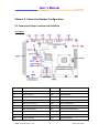
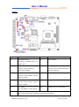
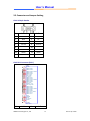
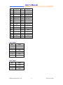
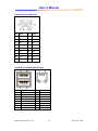
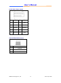
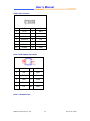
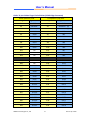
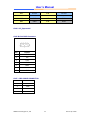
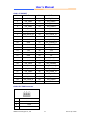
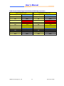
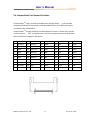
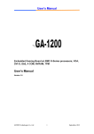
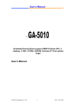
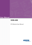
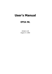
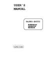
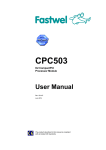
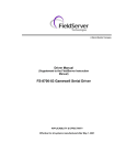
User’s Manual Embedded Gaming Board w/ AMD G-Series processors, VGA, DVI-I, GbE, 4 COM, NVRAM, TPM User’s Manual AEWIN Technologies Co., Ltd 1 Ver.1.5 Apr. 2014 User’s Manual © Copyright 2010. All Rights Reserved Manual Edition 1.0, September, 2012 This document contains proprietary information protected by copyright. All rights are reserved; no part of this manual may be reproduced, copied, translated or transmitted in any form or by any means without prior written permission of the manufacturer. The content of this document is intended to be accurate and reliable; the original manufacturer assumes no responsibility for any inaccuracies that may be contained in this manual. The original manufacturer reserves the right to make improvements to the products described in this manual at any time without prior notice. Trademarks IBM, EGA, VGA, XT/AT, OS/2 and PS/2 are registered trademarks of International business Machine Corporation Award is a trademark of Award Software International, Inc Intel is a trademark of Intel RTL is a trademark of Realtek VIA is a trademark of VIA Technologies, Inc Microsoft, Windows, Windows NT and MS-DOS are either trademarks or registered trademarks of Microsoft Corporation All other product names mentioned herein are used for identification purpose only and may be trademarks and/or registered trademarks of their respective companies Limitation of Liability While reasonable efforts have been made to ensure the accuracy of this document, the manufacturer and distributor assume no liability resulting from errors or omissions in this document, or from the use of the information contained herein. For more information on GA-1210 or other AEWIN products, please visit our website http://www.aewin.com.tw. For technical supports or free catalog, please send your inquiry to [email protected] AEWIN Technologies Co., Ltd 2 Ver.1.5 Apr. 2014 User’s Manual Revision History Rev.1.0 Original copy Rev1.1 Wording correction. Rev1.2 Include Jumper setting, JP11, JP12, JP13 Rev1.3 OS support update Rev.1.4 Display support setup Rev.1.5 Display support BIOS setup & update AEWIN Technologies Co., Ltd 3 Ver.1.5 Apr. 2014 User’s Manual Table of Contents Chapter 1. General Information ..................................................................................... 5 1.1 Introducing ....................................................................................................... 5 1.2 Specification ..................................................................................................... 5 1.3 Order Information ............................................................................................ 8 1.4 Packaging.......................................................................................................... 8 1.5 Precautions ...................................................................................................... 9 1.6 Board Placement ............................................................................................ 10 1.7 Board / System Dimension ............................................................................. 12 Chapter 2. Connector/Jumper Configuration .............................................................. 14 2.1 Connector/Jumper Location and Definition .................................................. 14 2.2 Connector and Jumper Setting ...................................................................... 16 2.3 CompactFlash Card Socket Pin Define ........................................................... 25 Chapter 3. BIOS Setup .................................................................................................. 26 3.1 Quick Setup .................................................................................................... 26 3.2 Entering the CMOS Setup Program ................................................................ 27 3.3 Menu Options ................................................................................................ 28 3.4 Advanced Menu ............................................................................................. 29 3.5 Chipset Menu ................................................................................................. 36 3.6 Boot Menu ..................................................................................................... 39 3.8 Exit.................................................................................................................. 41 Appendix A: System Resources .................................................................................... 42 Appendix B: Development Kit (optional) ..................................................................... 45 AEWIN Technologies Co., Ltd 4 Ver.1.5 Apr. 2014 User’s Manual Chapter 1. General Information 1.1 Introducing GA-1210, an All-In-One Gaming System / Board with the powerful AMD Fusion computing/ graphics capabilities, VGA + DVI-I display interfaces, complete COMs, NVRAM, Gaming I/Os, diversify security options, on-board audio power amplifier, … and more, which offers the best cost/performance you can ever find from the market. Even more with both linux and Windows Embedded Compact 7 low cost operating systems supports you optimize your system overall expenses deeper. Fan-less system design cope with selected AMD T16R or T40R low power APU (on request ) provide you more system reliabilities. Easy unplugable 72-pin golden finger best suit for all gaming kits and machines refurbish market. 1.2 Specification ■ System CPU AMD® T52R Single Core 1.5GHz BIOS AMI® BIOS Chipset AMD® A50M chipset System Memory 1 x DDR3-1066/1333* SODIMM socket support up to 4GB * T52R SKU support DDR3-1333 memory Watchdog Timer 255 levels timer interval, (1sec. to 255min.), setup by software. ■ Display Video Chipset AMD® T52R w/ ATI® Radeon™ HD6310 - Microsoft® DirectX® 11 - OpenGL 4.0 - OpenCL 1.0 - UVD (Universal Video Decoder) 3.0; Full bitstream decoding of H.264/MPEG-4 AVC, VC-1, DivX, Xvid, MPEG2, as well as Blu-ray 3D Video Interface T52R SKU: 2560 x 1600 resolution is supported on dual monitors 1 x DVI-I 1 x VGA ■ Audio Audio Chipset HDA AEWIN Technologies Co., Ltd 5 Ver.1.5 Apr. 2014 User’s Manual Power amp. 6W Stereo power amp. Audio Interface 2x amplified speaker out through golden finger ■ Ethernet Ethernet Interface One Gigabit Ethernet ■ Storage SSD 1 x CF socket Or 2GB NANDrive (PATA interface) (optional) HDD Two SATA connectors ■ Security Physical Security Onboard Storage (optional) Software Security TPM 1.2 (optional) FPGA A3P125-FG144 ■ Gaming NVRAM On-board battery-less backup MRAM 32KB or optional 512KB MRAM Timers Programmable timer with timeout interrupt Digital I/O 31 x ESD Protected Input 26 x current sink output (ULN2803) ■ Expansion Expansion slot PCI-E x4 (PCI-E x16 slot) ■ System I/O COM 4 x COM ․COM1 support Full RS-232 (external DB9) ․COM2 support simple RS-232/ RS-485 (external DB9) ․COM3 support simple RS-232 (internal pin header) or cctalk (jumper select) ․COM4 support simple RS-232 (internal pin header) USB 6 x USB2.0 - 2 x USB 2.0 port at rear I/O - 4 x USB 2.0 (pin header) ■ Power Supply Voltage DC 5V & DC12V input from 20-pin Golden finger ■ Software O/S Microsoft ® Windows ® WES7 / WEC7 and Linux Ubuntu 10/11 support ■ Mechanical and Environment Environmental Operating Temperature: 0 – 60 ºC (32 ºF – 140 ºF) Storage Temperature: -20 – 85 ºC (-4 ºF – 185 ºF) Relative Humidity: 10-85 % RH, non-condensing AEWIN Technologies Co., Ltd 6 Ver.1.5 Apr. 2014 User’s Manual Compliant FCC/CE Class A Dimension 170mm (L) x 200mm (W) (8.7” L x 11.6” W) ■ Applications Main Application Video slot machines Fruit machines Video lottery terminals Amusement game machines Betting terminal of multiplayer table game or roulette AEWIN Technologies Co., Ltd 7 Ver.1.5 Apr. 2014 User’s Manual 1.3 Order Information GA-1210A AMD T52R Single Core 1.5GHz based Gaming Board with VGA, DVI-I, 1x GbE, 4x COM, USB, SATA, CF, 32KB MVRAM, PCIe slot GA-1210B AMD T52R Single Core 1.5GHz based Gaming Board with VGA, DVI-D, 1x GbE, 4x COM, USB, SATA, CF, 32KB MVRAM, PCIe slot Optional DK-GA1210-01 Development Kit R217AA Gaming I/O testing board 46L-G00027-00 72 pin golden finger cable of GA-1210 (for CN13) 46L-JAM002-00 20 pin golden finger power cable of GA-1210 (for CN20) 46L-IUSB01-00 Dual port USB cable (for CN7, CN8) 46L-SATA07-00 SATA cable (for CN15, CN16) 46L-IPOW65-00 4 pin SATA Power cable (for CN17) 46L-POW002-00 GF to ATX power cable w/ fool-proof * Note: All specifications are subject to change without prior notice 1.4 Packaging Please make sure that the following items have been included in the package before installation. 1. GA-1210 board 2. Quick Installation Guide (Optional) 3. Cables (Optional) 4. CD-ROM that contains the following folders: (1) Manual (2) Driver If any item of above is missing or damaged, please contact your dealer or retailer from whom you purchased the GA-1210. Keep the box and carton when you probably ship or store GA-1210 in near future. After you unpack the goods, inspect and make sure the packaging is intact. Do not plug the power adapter to the appliance of GA-1210 if you already find it appears damaged. Note: Keep the GA-1210 in the original packaging until you start installation. AEWIN Technologies Co., Ltd 8 Ver.1.5 Apr. 2014 User’s Manual 1.5 Precautions Please make sure you properly ground yourself before handling the GA-1210 board or other system components. Electrostatic discharge can be easily damage the GA-1210 board. Do not remove the anti-static packing until you are ready to install the GA-1210 board. Ground yourself before removing any system component from it protective anti-static packaging. To ground yourself, grasp the expansion slot covers or other unpainted parts of the computer chassis. Handle the GA-1210 board by its edges and avoid touching the components on it. AEWIN Technologies Co., Ltd 9 Ver.1.5 Apr. 2014 User’s Manual 1.6 Board Placement PCI-e x16 slot CF or 2GB DDR3 CPU NANDrive SATA SO-DIMM +5V & +12V 72 Pins DC in Golden finger (optional) GbE VGA AEWIN Technologies Co., Ltd DVI-I USB 10 COM1 & 2 COM3 & 4 Ver.1.5 Apr. 2014 User’s Manual Display Combination Support There are two display interface existed on the board, one is VGA, the other one is DVI-I. Through BIOS setting as mentioned at following table, board could support variety display output. BIOS IGD(CRT+DVI) IGD(CRT+CRT) IGD(CRT) VGA only VGA VGA VGA DVI-D only DVI No display No display DVI-A only No display DVI-A No display DVI-D+VGA DVI VGA DVI VGA DVI VGA VGA+DVI-A VGA + DVI-A VGA + DVI-A VGA + DVI-VGA Display Word in Black : No display Word in Green : function Word in Red : Tearing display Note : Once loss display, please reboot system and enter BIOS menu for display setting confirmation. Please check BIOS setting of display that mentioned at above table according to exactly display monitors connected. Note : For two VGA display, DVI-I include VGA display function(DVI-A), customer can have VGA output from DVI-I connector by setup bios and DVI-to-VGA cable or adapter. AEWIN Technologies Co., Ltd 11 Ver.1.5 Apr. 2014 User’s Manual 1.7 Board / System Dimension AEWIN Technologies Co., Ltd 12 Ver.1.5 Apr. 2014 User’s Manual Golden Finger DVI-I GbE USB VGA COM 3 COM4 COM 1 COM2 AEWIN Technologies Co., Ltd 13 Ver.1.5 Apr. 2014 User’s Manual Chapter 2. Connector/Jumper Configuration 2.1 Connector/Jumper Location and Definition Connector: Connector Define Connector Define CN1 VGA Connector CN11 FPGA DOWNLOAD PIN CN2 DVI-I Connector CN12 FPGA RESERVED CN3 COM 3 (SIM232&CCTALK) CN13 GOLDEN-FINGER1 CN4 COM 4 (SIM232) CN14 PCI_EXPRESS_X4 (x16 slot) CN5 COM 1 & 2 Connector CN15 SATA 1 CONNECTOR CN6 RJ45&USB 0/1 CN16 SATA 2 CONNECTOR CN7 USB 4/5 PIN HEADER CN17 SATA POWER CONNECTOR CN8 USB 2/3 PIN HEADER CN18 CF Socket CN9 SYSTEM FAN CONNECTOR CN19 CPU FAN CONNECTOR CN10 LPC PIN HEADER CN20 GOLDEN-FINGER2 AEWIN Technologies Co., Ltd 14 Ver.1.5 Apr. 2014 User’s Manual Jumper: Connector Define Connector Define JP1 COM2 MODE SELECT JP6 FPGA RESERVED JP7 AUDIO ON/OFF (1-2: RS232 ; 3-4: RS485 4-Wire ; 5-6: RS485 2-Wire) JP2 COM2 MODE SELECT JP3 (1-3short 2-4short: RS232 ; 3-5 (1-3short 2-4short: Audio ON; 3-5short short4-6 short: RS485) 4-6short: Audio OFF) COM3 MODE SELECT JP8 NANDrive_WP_N(1-2:ON 2-3:OFF) JP9 RESET JP10 EEPROM_WP_N (1-2:ON 2-3OFF) (1-3short 2-4short: SIM232; 3-5short 4-6short: CCTALK) JP4 COM2 MODE SELECT (1-3short 2-4short : RS232 ; 3-5short 4-6short : RS485) JP5 Clear CMOS (1-2: Hold CMOS; 2-3: Clear CMOS) JP11, 12, 13 Golden finger Power (1-2:+5V ; 2-3:+12) Note : Please setup jumper according to external I/O voltage usage. AEWIN Technologies Co., Ltd 15 Ver.1.5 Apr. 2014 User’s Manual 2.2 Connector and Jumper Setting CN1: VGA pin header Pin Define Pin Define 1 RED 2 GREEN 3 BLUE 4 NC 5 Ground 6 Ground 7 Ground 8 Ground 9 +5V 10 Ground 11 NC 12 SDA 13 HSYNC 14 VSYNC 15 SCL CN2: DVI Connector (DVI-I) CN3A M1 CASE1 CK1 CK2 CK3 CK4 CK5 CK6 CK7 CK8 CK9 CK10 CK11 CK12 CK13 CK14 CK15 CK16 CK17 CK18 CK19 CK20 CK21 CK22 CK23 CK24 TMDS Data2TMDS Data2+ TMDS Data2/4 Shield TMDS Data4TMDS Data4+ DDC Clock DDC Data A VSY NC TMDS Data1TMDS Data1+ TMDS Data1/3 Shield TMDS Data3TMDS Data3+ +5V Power GND(f or +5V) Hot Plug Detct TMDS Data0TMDS Data0+ TMDS Data0/5 Shield TMDS Data5TMDS Data5+ TMDS Clock Shield TMDS Clock+ TMDS Clock- C1 C2 C3 C4 C5 RED GREEN BLUE A HSY NC AGND M2 CASE2 DUAL DVI-I Pin Define Pin AEWIN Technologies Co., Ltd Define 16 Ver.1.5 Apr. 2014 User’s Manual M1 CASE GND M2 CASE GND CK1 DP0_TX0_N CK2 DP0_TX0_P CK3 GND CK4 - CK5 - CK6 DP0_AUX_P CK7 DP0_AUX_N CK8 - CK9 DP0_TX1_N CK10 DP0_TX1_P CK11 GND CK12 - CK13 - CK14 +5V CK15 GND CK16 DVID_HPD CK17 DP0_TX2_N CK18 DP0_TX2_P CK19 GND CK20 - CK21 - CK22 GND CK23 DP0_TX3_N CK24 DP0_TX3_P C1 Red C2 Green C3 Blue C4 Hsync C5 AGND CN3 : COM3 Pin Define 1 +12V 2 CCTALK 3 GND 4 SOUT 5 SIN 6 GND CN4 : COM4 Pin Define 1 SOUT 2 SIN 3 GND AEWIN Technologies Co., Ltd 17 Ver.1.5 Apr. 2014 User’s Manual CN5:COM1 and COM2 Jack Pin Signal Pin Signal A1 DCD B1 DCD A2 RXD B2 RXD A3 TXD B3 TXD A4 DTR B4 DTR A5 Ground B5 Ground A6 DSR B6 DSR A7 RTS B7 RTS A8 CTS B8 CTS A9 R1 B9 R1 CN6:USB and 100/10 LAN RJ45 Jack Pin 1 2 3 4 5 6 7 8 Signal 5VUSB0 USBDT0USBDT0+ Ground 5VUSB0 USBDT1USBDT1+ Ground AEWIN Technologies Co., Ltd Pin Signal 1 2 3 4 5 6 7 8 TX+ TXN/C Ground Ground N/C RX+ RX- 18 Ver.1.5 Apr. 2014 User’s Manual CN7 & CN8: USB pin header Pin Define Pin Define 1 +5V 2 +5V 3 P0DATA- 4 P1DATA- 5 P0DATA+ 6 P1DATA+ 7 GND 8 GND 9 Reserved 10 GND CN9: SYSTEM FAN Connector Pin Define 1 Ground 2 +12V 3 NC AEWIN Technologies Co., Ltd 19 Ver.1.5 Apr. 2014 User’s Manual CN10: LPC Connector Pin Define Pin Define 1 +3.3V 2 AD 0 3 AD 1 4 AD 2 5 AD 3 6 Frame# 7 PCIERST# 8 +5V 9 CLOCK 10 PME# 11 GND 12 13 SERIRQ 14 LDRQ CN11: FPGA Update Pin Header CN17 1 3 5 7 9 2 6 8 10 Pin Header 2*5(2.54mm) Pin Define Pin Define 1 TCK 2 GND 3 TDO 4 NC 5 TMS 6 VJTAG 7 VPUMP 8 TRST 9 TDI 10 GND CN12 : FPGA Reserved AEWIN Technologies Co., Ltd 20 Ver.1.5 Apr. 2014 User’s Manual CN13: 72-pin Golden Finger Pin Definition (PCB & Edge Connector) Solder (Bottom) Side Component (Top) Side Golden Finger Pin# Signal Name Golden Finger Pin# Signal Name B1 GND A1 GND B2 SPEAKER - A2 SPEAKER + (R) B3 SPEAKER - A3 SPEAKER + (L) B4 IN19 A4 IN0 B5 IN20 A5 IN1 B6 IN21 A6 IN2 B7 IN22 A7 IN3 B8 IN23 A8 IN4 B9 IN24 A9 IN5 B10 IN25 A10 IN6 B11 Nc A11 IN7 B12 Nc A12 IN8 B13 Nc A13 IN9 B14 A14 B15 Nc A15 IN11 B16 Nc A16 IN12 B17 IN26 A17 IN13 B18 IN27 A18 IN14 B19 IN28 A19 IN15 B20 IN29 A20 IN16 B21 IN30 A21 IN17 B22 IN31 A22 IN18 B23 OUT12 A23 OUT0 B24 OUT13 A24 OUT1 B25 OUT14 A25 OUT2 B26 OUT15 A26 OUT3 B27 OUT16 A27 OUT4 B28 OUT17 A28 OUT5 B29 OUT18 A29 OUT6 B30 OUT19 A30 OUT7 B31 OUT20 A31 OUT8 B32 OUT21 A32 OUT9 AEWIN Technologies Co., Ltd 21 Ver.1.5 Apr. 2014 User’s Manual B33 OUT22 A33 OUT10 B34 OUT23 A34 OUT11 (ULN2803) B35 GND A35 GND B36 GND A36 GND CN14 : PCI_Expressx16 CN15 & CN16 SATA Connector Pin Define 1 GND 2 TXP 3 TXN 4 GND 5 RXN 6 RXP 7 GND CN17 : SATA POWER CONNECTOR Pin Define 1 +12V 2 GND 3 GND 4 +5V AEWIN Technologies Co., Ltd 22 Ver.1.5 Apr. 2014 User’s Manual CN18 : CF SOCKET Pin Define Pin Define 1 GND 26 CF_CD-1 2 IDE_PDD3 27 IDE_PDD11 3 IDE_PDD4 28 IDE_PDD12 4 IDE_PDD5 29 IDE_PDD13 5 IDE_PDD6 30 IDE_PDD14 6 IDE_PDD7 31 IDE_PDD15 7 IDE_PDCS1_N 32 IDE_PDCS3_N 8 GND 33 GND 9 GND 34 IDE_PDIOR_N 10 GND 35 IDE_PDIOW_N 11 GND 36 CF_PIN36 12 GND 37 IDE_IRQ 13 +5V 38 +5V 14 GND 39 GND 15 GND 40 NC 16 GND 41 IDE_RST_N 17 GND 42 IDE_PDIORDY 18 IDE_PDA2 43 IDE_PDDREQ 19 IDE_PDA1 44 IDE_PDDACK_N 20 IDE_PDA0 45 IDE_ACTP_N 21 IDE_PDD0 46 IDE_PDIAG_N 22 IDE_PDD1 47 IDE_PDD8 23 IDE_PDD2 48 IDE_PDD9 24 IDE_CS16_N 49 IDE_PDD10 25 NC 50 GND CN19: CPU FAN Connector Pin Define 1 Ground 2 +12V 3 NC AEWIN Technologies Co., Ltd 23 Ver.1.5 Apr. 2014 User’s Manual CN20: 20-pin Golden Finger Pin Definition (PCB & Edge Connector) Solder (Bottom) Side Component (Top) Side Golden Finger Pin# Signal Name Golden Finger Pin# Signal Name B1 GND A1 GND B2 GND A2 GND B3 +5V A3 +5V B4 +5V A4 +5V B5 +12V A5 +12V B6 +12V + R A6 +12V + R B7 OUT11 (MOSFET) A7 OUT11 (MOSFET) B8 A8 B9 GND A9 GND B10 GND A10 GND AEWIN Technologies Co., Ltd 24 Ver.1.5 Apr. 2014 User’s Manual 2.3 CompactFlash Card Socket Pin Define CompactFlashTM card is a small removable mass storage device. It can provide complete PCMCIA-ATA functionality and compatibility plus True IDE functionality compatible with ATA/ATAPI-4. CompactFlashTM storage products are solid state form factor, it means they contain no moving parts. Thus, it provides users with much greater protection of the data than conventional magnetic disk device. Pin Assignment Pin 1 Ground 2 Assignment Pin Assignment Pin 11 Ground 21 D00 D03 12 Ground 22 3 D04 13 VCC/+5V 4 D05 5 Pin Assignment 31 D15 41 RESET D01 32 CS 42 ORDY 23 D02 33 NC 43 DREG 14 Ground 24 WP 34 IOR 44 DACK D06 15 Ground 25 NC 35 IOW 45 LED 6 D07 16 Ground 26 NC 36 WE 46 BVD 7 CS 17 Ground 27 D11 37 RDY/BSY 47 D08 8 Ground 18 A02 28 D12 38 VCC/+5V 48 D09 9 Ground 19 A01 29 D13 39 SCSE 49 D10 10 Ground 20 A00 30 D14 40 NC 50 Ground AEWIN Technologies Co., Ltd 25 Assignment Ver.1.5 Apr. 2014 User’s Manual Chapter 3. BIOS Setup The ROM chip of your GA-1210 board is configured with a customized Basic Input/Output System (BIOS) from AMI BIOS. The BIOS is a set of permanently recorded program routines that give the system its fundamental operational characteristics. It also tests the computer and determines how the computer reacts to instructions that are part of programs. The BIOS is made up of code and programs that provide the device-level control for the major I/O devices in the system. It contains a set of routines (called POST, for Power-On Self Test) that check out the system when you turn it on. The BIOS also includes CMOS Setup program, so no disk-based setup program is required CMOS RAM stores information for: Date and time Memory capacity of the appliance Type of display adapter installed Number and type of disk drives The CMOS memory is maintained by battery installed on the GA-1210 board. By using the battery, all memory in CMOS can be retained when the system power switch is turned off. The system BIOS also supports easy way to reload the CMOS data when you replace the battery of the battery power lose. 3.1 Quick Setup In most cases, you can quickly configure the system by choosing the following main menu options: 1. Choose “Exit” “Load Optimal Defaults” from the main menu. This loads the setup default values from the BIOS Features Setup and Chipset Features Setup screens. 2. Choose “Main” & “Advanced” from the main menu. This option lets you configure the date and time, hard disk type, floppy disk drive type, primary display and more. 3. In the main menu, press F10 (“Save Changes and Exit”) to save your changes and reboot the system. AEWIN Technologies Co., Ltd 26 Ver.1.5 Apr. 2014 User’s Manual 3.2 Entering the CMOS Setup Program Use the CMOS Setup program to modify the system parameters to reflect the options installed in your system and to customize your system. For example, you should run the Setup program after you: Received an error code at startup Install another disk drive Use your system after not having used it for a long time Find the original setup missing Replace the battery Change to a different type of CPU Run the AMI Flash program to update the system BIOS Run the CMOS Setup program after you turn on the system. On-screen instructions explain how to use the program. Enter the CMOS Setup program’s main menu as follows: 1. Turn on or reboot the system. After the BIOS performs a series of diagnostic checks, the following message appears: “Press DEL to enter SETUP” 2. Press the <DEL> key to enter CMOS Setup program. The main menu appears: AEWIN Technologies Co., Ltd 27 Ver.1.5 Apr. 2014 User’s Manual Main: For changing the basic system configurations. Advanced: For changing the advanced system settings. Chipset: For changing the chipset settings. Boot: For changing the system boot configurations. Security: Use this menu to set User and Supervisor Passwords. Save&Exit: For selecting the exit options and loading default settings. In the main menu, press <F4> (“Save Changes and Exit”) to save your changes and reboot the system. Press <ESC> (“Exit”) to ignores your changes and exits the program. 3. Choose a setup option with the arrow keys and press <Enter>. See the following sections for a brief description of each setup option. 3.3 Menu Options The main menu options of the CMOS Setup program are described in the following and the following sections of this chapter. BIOS Information: Displays the auto-detected BIOS information. BIOS Vendor: Core Version: Compliancy: Project Version: Build Date and Time: Memory Information: Displays the auto-detected system memory. Total Memory: System Date [Day mm/dd/yyyy]: This item allows you to set the system date. SystemTime: [hour:min:sec]: This item allows you to set the system time. Access Level: This item allows you to set the authority to access system. AEWIN Technologies Co., Ltd 28 Ver.1.5 Apr. 2014 User’s Manual 3.4 Advanced Menu The Advanced menu items allow you to change the settings for the CPU and other system devices. Use the Advanced Setup option as follows: 1. Choose “Advanced” from the main menu. The following screen appears: 2. Use the arrow keys to move between fields. Modify the selected field using the PgUP/PgDN/+/- keys. Some fields let you enter numeric values directly. 3. After you have finished with the Advanced setup, press the <ESC> key to return to the main menu. AEWIN Technologies Co., Ltd 29 Ver.1.5 Apr. 2014 User’s Manual 3.4.1 Trusted Computing This sub menu allows you to set or change the configurations for the TPM function. Configuration TPM State: [Disabled] This item allows you to enable or disable security device. [Note]: Your computer will reboot during restart in order to change state of the device. Pending operation: [None] Current Status Information This information shows current status of TPM with following items. TPM Enabled Status: [Disabled] TPM Active Status: [Deactivated] TPM Owner Status: [UnOwned] AEWIN Technologies Co., Ltd 30 Ver.1.5 Apr. 2014 User’s Manual 3.4.2 CPU Information This sub menu shows the CPU-related information which is automatically detected by BIOS. CPU Information This information shows CPU information which using in the system. CPU information includes messages like processor type, power consumption under running frequency, operating speed as well as cache size. AEWIN Technologies Co., Ltd 31 Ver.1.5 Apr. 2014 User’s Manual 3.4.3 IDE Configuration This sub menu shows the IDE/SATA device information which is automatically detected by BIOS. IDE Configuration AEWIN Technologies Co., Ltd 32 Ver.1.5 Apr. 2014 User’s Manual 3.4.4 USB Configuration This sub-menu allows you to set the parameters to support USB devices you are going to use. Mass storage will be detected automatically by system. The menu also allows you to enable/disable legacy USB device and EHCI hand-off. AEWIN Technologies Co., Ltd 33 Ver.1.5 Apr. 2014 User’s Manual 3.4.5 Platform Function Display Mode, this item allows user change on board display method. (Note) This menu allows you to setup watch-dog, the timer can be set in second or minute mode. Note : For Display output types, please refer to page 34 (Display Combination Support) for more detail. AEWIN Technologies Co., Ltd 34 Ver.1.5 Apr. 2014 User’s Manual 3.4.6 Super IO Configuration Super IO function provides 4 ports IO for various control. Those ports can be configured respectively. AEWIN Technologies Co., Ltd 35 Ver.1.5 Apr. 2014 User’s Manual 3.5 Chipset Menu Use the Chipset Setup option as follows: 1. Choose “Chipset” from the main menu. The following screen appears. 2. Move between items and select values by using the arrow keys. Modify the selected field the PgUP/PgDN keys. For information on the various options, press <F1> key. 3. After you have finished with the Chipset Setup, press the <ESC> key to return to the main menu. AEWIN Technologies Co., Ltd 36 Ver.1.5 Apr. 2014 User’s Manual 3.5.1 North Bridge It allows you to configure the parameter of NorthBridge, includes clock, timing, VGA frame buffer and etc.. AEWIN Technologies Co., Ltd 37 Ver.1.5 Apr. 2014 User’s Manual 3.5.2 South Bridge It allows you to configure the parameter of SoughBridge, includes LAN, Audio and etc… AEWIN Technologies Co., Ltd 38 Ver.1.5 Apr. 2014 User’s Manual 3.6 Boot Menu Use the Boot Setup option as follows: 1. Choose “Boot” from the main menu. The following screen appears: 2. Move between items and select values by using the arrow keys. Modify the selected fields using the PnUP/PgDN Keys. For information on the various options, press <F1> key. 3. After you have finished with the Boot setup, press the <ESC> key to return to the main menu. AEWIN Technologies Co., Ltd 39 Ver.1.5 Apr. 2014 User’s Manual 3.7 Security Menu Use the Security Setup option as follows: 1. Choose “Security” from the main menu. The following screen appears: 2. Move between items and select values by using the arrow keys. Modify the selected fields using the PgUP/PgDN keys. Please press the <F1> key for information on the various options. 3. After you have finished with the Security setup, press the <ESC> key to return to the main menu. AEWIN Technologies Co., Ltd 40 Ver.1.5 Apr. 2014 User’s Manual 3.8 Exit The item allows you to save or discard your changes to the BIOS items, and load the optimal defaults or failsafe defaults for the BIOS items. Use the Exit option as follows: 1. Choose “Exit” from the main menu, the following screen appears. 2. Move between items and select values by using the arrow keys. Modify the selected fields using the PgUP/PgDN keys. For information on the various options, please press <F1> key. 3. Please press the <ESC> key to return the main menu after finishing with the Exit Options. AEWIN Technologies Co., Ltd 41 Ver.1.5 Apr. 2014 User’s Manual Appendix A: System Resources Interrupt Controller: The GA-1210 is a fully PC compatible appliance. If you would like to use extra add-on cards, please make sure that the IRQs do not conflict. Any remaining IRQs then may be assigned to this PCI Bus. You are able to use Microsoft’s Diagnostic (MDS.EXE) utility included in Windows directory to see their map. IRQ Assignment IRQ0 ISA/Timer IRQ1 ISA/Keyboard IRQ2 ISA/Interrupt re-routing from IRQ8 ~ IRQ15 IRQ3 ISA/COM2 IRQ4 ISA/COM1 IRQ5 ISA/Free IRQ6 ISA/FDD Controller IRQ7 PCI/PCI-PCI Bridge IRQ8 ISA/RTC IRQ9 ISA/Free IRQ10 PCI/IDE Controller IRQ11 PCI/VGA Adapter IRQ12 ISA/Mouse IRQ13 ISA/Coprocessor IRQ14 ISA/IDE Controller IRQ15 ISA/IDE Controller DMA Channel Assignment: Channel 4 is by default used to cascade to two controllers Channel Assignment DMA0 ISA/Free DMA1 ISA/Free DMA2 ISA/FDD Controller DMA3 ISA/Free DMA4 ISA/Cascade DMA5 ISA/Free DMA6 ISA/Free DMA7 ISA/Free AEWIN Technologies Co., Ltd 42 Ver.1.5 Apr. 2014 User’s Manual Memory Map: The following table indicates memory of GA-1210. The address ranges specify the runtime code length. Memory below 1 Mb (1 Mb ~ 635 KB) Address Range Type Owner A0000 ~ AFFFF ISA VGA Adapter B0000 ~ BFFFF ISA VGA Adapter C0000 ~ CE3FF ISA Adapter ROM F0000 ~ FFFFF ISA System BIOS Memory above 1 Mb (1 Mb ~ 1826816 KB) System Address Range Type Owner C0000000~CFFFFFF7 PCI VGA Adapter D0000000~D00FFFFF PCI PCI-PCI Bridge FEB00000~FEB3FFFF PCI VGA Adapter FEB49000~FEB49FFF PCI USB Controller FEB4C000~FEB4CFFF PCI USB Controller FEB4E000~FEB4EFFF PCI USB Controller FEB4F000~FEB4F3FF PCI IDE Controller FFFF0000~FFFFFFFF PCI Ethernet Controller Memory Map Start High Start Low Size High Size Type 00000000 00000000 00000000 0009EC00 Available 00000000 0009EC00 00000000 00001400 Reserved 00000000 000E0000 00000000 00020000 Reserved 00000000 00100000 00000000 6F804000 Available 00000000 6F904000 00000000 00101000 NVS Space 00000000 6FA05000 00000000 00008000 ACPI Space 00000000 6FA0D000 00000000 00001000 NVS Space 00000000 6FA0E000 00000000 0005C000 Reserved 00000000 6FA6A000 00000000 0001E000 NVS Space 00000000 6FA88000 00000000 00058000 Reserved 00000000 6FAE0000 00000000 00007000 NVS Space 00000000 6FAE7000 00000000 00419000 Available 00000000 FEC00000 00000000 00001000 Reserved AEWIN Technologies Co., Ltd 43 Ver.1.5 Apr. 2014 User’s Manual 00000000 FEC10000 00000000 00001000 Reserved 00000000 FED00000 00000000 00001000 Reserved 00000000 FED61000 00000000 00010000 Reserved 00000000 FED80000 00000000 00010000 Reserved 00000000 FEF00000 00000000 01100000 Reserved I/O Map: The addresses shown in the table are typical locations I/O Port Assignment 170 ~ 177 ISA/IDE Controller 1F0 ~ 1F7 ISA/IDE Controller 2E8 ~ 2EF ISA/COM4 2F8 ~ 2FF ISA/COM2 376 ~ ISA/IDE Controller 3B0 ~ 3BB ISA/VGA Adapter 3C0 ~ 3DF ISA/VGA Adapter 3E8 ~ 3EF ISA/COM3 3F6 ~ ISA/IDE Controller 3F8 ~ 3FF ISA/COM1 E000 ~ EFFF PCI/PCI-PCI Bridge F000 ~ F0FE PCI/VGA Adapter F100 ~ F10E PCI/IDE Controller F110 ~ F112 PCI/IDE Controller F120 ~ F126 PCI/IDE Controller F130 ~ F132 PCI/IDE Controller F140 ~ F146 PCI/IDE Controller AEWIN Technologies Co., Ltd 44 Ver.1.5 Apr. 2014 User’s Manual Appendix B: Development Kit (optional) The GA-1210 offers R217A Gaming I/O testing board and some cables for development use. DK-GA1210-01 Item & Description Gaming I/O testing board 72 pin golden finger cable 20 pin golden finger power cable SATA cable 35cm 4 pin SATA power cable 25cm Dual port USB cable 25cm GF to ATX power cable w/ fool-proof R217A-01 Part No. R217A-01 46L-G00027-00 46L-JAM002-01 46L-SATA07-00 Qty 1 1 1 1 46L-IPOW65-00 46L-IUSB01-00 46L-POW002-00 1 1 1 46L-G00027-00 46L-SATA07-00 46L-JAM002-01 46L-IPOW65-00 AEWIN Technologies Co., Ltd 46L-IUSB01-00 45 Ver.1.5 Apr. 2014 User’s Manual 46L-POW002-00 AEWIN Technologies Co., Ltd 46 Ver.1.5 Apr. 2014