Transcript
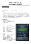
TOYO Voltage Detector
Installation Manual
A. Introduction
TOYO Voltage Detector is using capacitive circuit in series to generate voltage between two ends of the
circuit’s impedance, and then using neon light as indication. When the main line is electrified, the neon
indicator will light up.
v
Main Line (R/S/T)
main line voltage = V
capacitance = C1C2......Cn
Voltage Detector
C=
C1
Indicator
Push button switch
C2
I
1
1
1
1
+
+ LLL
C1 C 2
Cn
charging current=i
VD impedance=r
Varister
Cn
V
i=
r2 +
Neon
light
U
r
VD voltage=U
1
ωC
2
ω 2C 2 r 2 ≈ 0
i=
ωCV
ω C 2r 2 + 1
2
i ≈ ωCV
Therefore, VD voltage U = r × i = 2πfCV ⋅ r
<Equivilent Circuit Diagram>
B. Attention
1. When installing the VD, the main line (busbar) must be directly mounted on the VD.
DO NOT use wire to connect main line (busbar) and VD.
main line (R/S/T)
main line (R/S/T)
2. For VD of only 1 busbar fixing hole, the thickness of -shaped busbar fixer should be >6mm galvanized
iron. For VD of 2 busbar fixing holes, the thickness of -shaped busbar fixer should be >6mm galvanized
iron.
3. For VD of only 1 fixing hole at its bottom, there are 2 elliptic holes for extra fixing to prevent VD from
moving while installation or happening of short circuit. Each VD should be fixed with 2 extra 5/32” screws
to prevent moving.
4. Regardless of the current rating, the size of main line busbar should be at least ≥50x5mm and with
conductivity ≥98%.
總 公 司: 台北市內湖區行愛路 68 號 6 樓
台中辦事處: 台中市文心路四段 200 號 10 樓之2
電
話: (02)8791-8588 傳 真:(02)8791-9588 電
話: (04)2296-9388 傳 真:(04)2296-9386
高雄辦事處: 高雄市民生一路56號15樓之6
電 子 郵 件: [email protected]
網
址: www.toyotech.com.tw
電
話: (07)227-2133 傳 真:(07)227-2173
