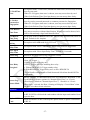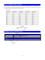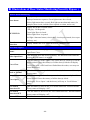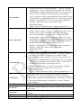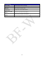
1
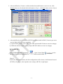
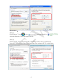
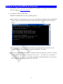
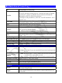
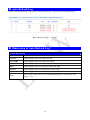
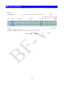
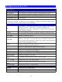
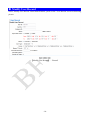
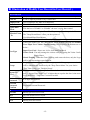
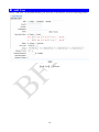
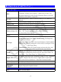
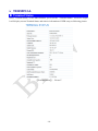
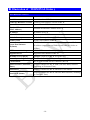
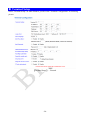
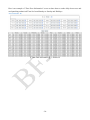
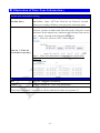
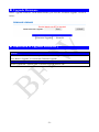
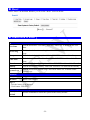
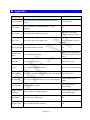
BF-W Web User Manual For 1.00.00: Jul-18th-2012 (HW1.0) BF-W Series Web Ver 1.0 Build Date Jul-17th-2012 【Contents】 -WEB Configuration- ...................................................................................................................1 WEB Logon .........................................................................................................................1 Preparation ...........................................................................................................................1 How to search BF-W............................................................................................................1 How to log on to BF-W web browser ..................................................................................5 TERMINAL STATUS ......................................................................................................................7 Illustration of Terminal Status:..........................................................................................8 USER ADMINISTRATION ................................................................................................................................... 9 Access Log...........................................................................................................................9 Illustration of Access Log: ..............................................................................................10 Auto Refresh Log............................................................................................................... 11 Illustration of Auto Refresh Log: .................................................................................... 11 View User List ...................................................................................................................12 Illustration of User List: ..................................................................................................13 Modify User Record...........................................................................................................14 Illustration of Modify User Record in User Record: ......................................................15 Add User ............................................................................................................................16 Illustration of Add New User: .........................................................................................17 TERMINAL .................................................................................................................................................... 18 Terminal Status...................................................................................................................18 Illustration of TERMINAL Status: ...............................................................................19 Terminal Setup ...................................................................................................................20 Illustration of Terminal Configuration: ...........................................................................21 Password Setup ..................................................................................................................23 Illustration of WEB Logon Setting/ Entrance Password: ...............................................24 System Log ........................................................................................................................26 Illustration of System Log: .............................................................................................26 Clock Setup ........................................................................................................................27 Illustration of System Clock Setup: ................................................................................27 ACCESS CONTROL .................................................................................................................................. 28 Time Set .............................................................................................................................28 Illustration of Time Set: ..................................................................................................28 Time Zone Setup ................................................................................................................29 Illustration of Time Zone List: ........................................................................................29 Illustration of Time Zone Information: ...........................................................................31 Group List ..........................................................................................................................32 Illustration of Group List: ...............................................................................................32 Illustration of Group Information: ..................................................................................33 Holiday Setup.....................................................................................................................34 Illustration of Holiday Setup:..........................................................................................34 Door Setup .........................................................................................................................35 Illustration of Door Setting: ............................................................................................36 Set up BF-50 with card list ................................................................................................38 Illustrations of BF-50 Card: ............................................................................................38 Remote Control ..................................................................................................................39 Illustrations of Door Status Monitoring/Security Bypass: ..............................................40 Event Handle......................................................................................................................41 Illustration of Event Handle:...........................................................................................43 TOOLS ................................................................................................................................................................. 47 IP Camera...........................................................................................................................47 Illustration IP Camera: ....................................................................................................47 BACKUP ...........................................................................................................................48 Illustration of Backup: ....................................................................................................48 RESTORE ..........................................................................................................................49 Illustration Restore:.........................................................................................................49 Reboot ................................................................................................................................50 Illustration of Reboot: .....................................................................................................50 Upgrade Firmware .............................................................................................................51 Illustration of Upgrade Firmware: ..................................................................................51 Reset...................................................................................................................................52 Illustration of Reset:........................................................................................................52 Appendix............................................................................................................. Appendix 1 Copyright @ 2011. All Rights Reserved. Document Version: 1.0《2011-05-24》 All trademarks and trade names are the properties of their respective owners. -WEB Configuration- WEB Logon BF-W contains a HTTP server, thus BF-W can link and connect through Web Browser, and then conduct setting. Preparation Before conducting BF-W setting, please assure the following: ● PC has connected to BF-W, and PC and BF-W are situated in the same WAN with power supplied. ● If the default IP address (192.168.0.66 ) is occupied by else device, then it is a must to shut down that device first till the setting is over, and then allocate new IP address to BF-W. How to search BF-W 1、After installation of BF-W and network cable is completed, use BF-W’s SEMAC Searsh to search all BF-W in a certain LAN, or download SEMAC Searsh tool from CHIYU homepage. Desktop icon as below: 2、Click SEMAC Searsh Picture icon, will display a window, as shown: -1- 3、While the SEMAC Searsh window shows up, it will display all BF-W in LAN, and show its Terminal ID, Model Name, IP Address, Subnet Mark, Gateway, Mac Address, Software IP. Select particular BF-W, then its related information will appear below the window, as shown: 4、The showed information of BF-W can be revised directly in the window, the part can be modified: IP Address, Subnet Mask, Gateway, Software IP, Software Port, Terminal ID. After modification completed ( MAC Address can not modify ),click Alter then it will display the modified information, as shown: -2- 5、After modification, if want to confirm whether the modification is correct or not, click Refresh button to refresh and check information ( Fig-1 ), click Exit button to leave.(Fig-2) 6、After modification, the IP address of BF-W has matched with its WAN, if want to get access into the Web of BF-W, has two methods: (1) Open SEMAC Searsh, select and double click particular BF-W, then to enter its webpage. (2) While the internet explorer opened, input BF-W IP address to enter its webpage WINDOWS XP: 《Step 1》 Click WINDOWS XP my computer , Open Control Panel left side, please turn to traditional overview and select network link on the 《Step 2》 Click LAN, then select content, the link configuration will be shown, click Internet Protocol (TCP/IP) as left figure, then input the same setting as BF-W, as right figure: -3- WINDOWS 7: 《Step 1》 Click Windows 7 icon, select click Alter Interface Card on the upper-left side. , open and search for , 《Step 2》 Click LAN link, select content, then the LAN settings will be shown, click Internet Protocol(TCP/IPv4), as left figure, click and input same setting as BF-W, as right figure. -4- How to log on to BF-W web browser 1、Start Web browser ( ig: WIN 7 IE ), input BF-W IP Address, for example: use the default BF-W IP Address: http://192.168.0.66 2、If connection failed, should check: ■ If BF-W installed and its power supplied properly ■ To examine the LAN connection, can use start toolsExecuteInput cmd open MS-DOS, Input “ ping” to test BF-W connection, input command: ping 192.168.0.66, as shown below: ■ If no response received, it explains the link has troubles either the connection is not proper or the PC’s IP address can not match with BF-W’s IP address ■ Set the PC’s IP address with BF-W’s IP address with same segment, if the PC uses fixed IP address, the address must be ranged in: 192.168.0.1 ~ 192.168.0.65 or 192.168.0.67 ~ 192.168.0.254 , thus it can be compatible with BF-W’s default IP address: 192.168.0.66, the “ Subnet Mask’s setting must be: 255.255.255.0 -5- 3、If the connection with BF-W is successful, then it will display a message window for User name and Password, the default for user name and Password is: admin/admin, as shown below: 4、While the user name and password entered, a Web setting interface of BF-W will be showed, enter it will then display a “ Quick Setup “ page. -6- Terminal Status When installation has completed and connected with BF-W, a Terminal Status window ”as below will pop up: 【Terminal Status】- Picture1 -7- Illustration of Terminal Status: Browse the Function Menu Bar at the left side of the Main Window by IE Browser ▼ USER ADMINISTRATION Switch to the “Access Log “ screen. Access Log Instant Access to records Display View User List Switch to the “User List” screen to Modify, Delete, Deactivate and Activate the data. Add User Switch to the “User RECORD” screen and “Add New User”. ▼ Auto Refresh Log Terminal Switch to the “Terminal Status” screen Terminal Setup Switch to the “Terminal Setup” screen. Password Setup Switch to the “WEB Logon Setting “ and “ Entrance Password” screen. System Log Switch to the “System Log“ screen. Clock Setup Switch to the “SYSTEM CLOCK SETUP “ screen. ▼ Terminal Status Access Control Switch to the “Time Set“ screen. Time Zone Setup Switch to the “Time Zone List“ screen. Group List Switch to the “Group List“ screen. Holiday Setup Switch to the “Holiday Setup“ screen. Door Setup Switch to the “Door Setting“ screen. Remote Control Switch to the “Door Status Monitoring“ and “Security Bypass” screen. Event Handle Switch to the “Event Handle“ screen. Multiple Badge Set up multiple badge combination for access control purpose. 2~3 user per set, up to 10 combination set support. ▼ Time Set Tools IP Camera 1. Set up IP address, type, username and password for the IP Camera. 2. Display snapshot picture captured from the IP Camera (only latest one) Backup Switch to the “Backup personnel data, terminal data “ screen. Restore Switch to the “Restore personnel data, terminal data “ screen. Reboot Switch to the “Reboot System“ screen. Upgrade Firmware Switch to the “Firmware Upgrade“ screen. Reset 1. Delete User Data. Access Logs. Group Time Zone. Time Set. Holiday. System Logs 2. Switch to the “Factory Default“ screen. ▼ BUTTON Refresh Refresh the WEB Status. -8- User Administration Access Log Select “Access Log” on the Main Window, you’ll see the “Access Log” screen as following picture: 【Access Log】- Picture2 -9- Illustration of Access Log: Serial Number of Access Logs User ID will be showed for the user who has access the door. By clicking “User ID” will direct current screen to “User Record ”page to “Modify User Record” ( picture 4). Should it be not connected, it means the User ID information of the User ID has been deleted. * The figure in the parentheses( ) after the “User ID” means the user’s level as 1~10. A Name registered for the User to get IN/OUT. When the registered User Name information without “Name”, this column will be blank. Date A Date allowed for the User to get IN/OUT. Time A Time allowed for the User to get IN/OUT. IN: Access by WEBPASS IN/OUT OUT: Access by Wiegand Reader ※ APB level will be shown followed the IN/OU Door No. It stands for the Door Number Controlled By BF-W Show up the relative IN/OUT records automatically as Anti-Duress, Fire Note Alarm......etc. The First Page Back to the 1st IN/OUT records page. The Former 10 Pages Forwarding 10 pages from the current IN/OUT records page. 1 2 3…N Page Change to any IN/OUT records page assigned. The Latter 10 Pages Backwards 10 pages from the current IN/OUT records page. The Last Page Fly to the last IN/OUT records page directly. Query and Export 1. User:Check the user, can search the user records, and export the file out Type 2. Event:Check the Event, can search the Event records, and export the file out 1. Single:Can only query / export a single user's access to records or 5 User ID or Card records of the event within an event Number 2. All:Can query / export all of the Access record or record of events StartDate/End Date Select the date by “Drop Down Menu”. ▼ No. Enter user ID to query Searchable/Export Card No Enter Card No to query Searchable/Export Event Button Click event Enter Event type query 5 maximum query event types. ▼ User ID Search Export Set the Search Requirement Click button to Search access records to demonstrate Requirement. Set the Export Requirement Click button to Export requirement TEXT or Excel file. - 10 - Auto Refresh Log Select “Auto Refresh Log” will see the “Auto Refresh Log” screen as the following picture: 【Auto Refresh Log】- Picture3 Illustration of Auto Refresh Log: ▼ Auto Refresh Log Serial Number. No. User ID Instant Display Access records User ID. User Name Instant Display Access records User Name. Date Instant Display Access records user enter/out date. Time Instant Display Access records user enter/out Time. IN/OUT Instant Display Access records user IN/OUT Log Door Instant Display Door Note. Show up the relative IN/OUT records automatically as Anti-Duress, Fire Alarm......etc. - 11 - View User List Select ”View User List” on the Main Window, you’ll see the “User List ” screen as following picture: 【User List】- Picture4 - 12 - Illustration of User List: ▼ ▼ ▼ Search User By “User ID” Select “User ID” and enter “User ID” in the textbox to search. By “Card No.” Select “Card No.” and enter “Card No.” in the textbox to search. By “User Name” Select “User Name.” and enter “User Name” in the textbox to search. By “Employee ID” Select “Employee ID” and enter “Employee ID” in the textbox to search Click button ”GO” Start to search. Steps : 1. Enter your “User ID”, “Card No or ” or “User Name” or “Employee ID” in the “blank textbox”. 2. Click button “GO” to search certain user from database. User List Serial Number. Tick the box before the “Serial Number” and Click the button of “Activate” , “Deactivate” or “Delete” to manage the No. authorization of “Activate” , “Deactivate” or “Delete” for selected users, multi-selection is allowed. User ID User’s ID. Click the “User ID” to enter the “Modify User Record” page Employee ID Display “Employee ID” for user User Name Display “User Name” for user Types of the system User. Whenever “User Type” is set up in the screen of “Modify User Record”, User Type this page will display Normal User, Super User, Visitor, Guard Touring and Defense Card according to the setup. Display user’s authorization status. Green Light means the user’s authority Active is activated, otherwise it is not activated. F When user’s Fingerprint has registered, green light lit. P When user’s Personal Password registered, green light lit. C When user’s card registered, green light lit. Verification mode Display user’s verification mode: (F: Fingerprint/P: Password/C: Card) Bypass Level Display the user’s Time Zone level of Bypass from L1~L10. The First page Back to the 1st page of “User List”. The Former 10 Forwarding 10 pages from the current “User List” page. pages 1 2 3…N page Change to any “User List” page assigned. The Latter 10 Backwards 10 pages from the current “User List” page. pages The Last Page Fly to the last “User List” page directly. Button Activate Activate the User’s authorization. Deactivate Deactivate the User’s authorization. Delete Delete the User’s information registered. - 13 - Modify User Record Select "Modify User Record" on the Main Window, you'll see the " User Record" screen as following picture: 【Modify User Record】- Picture5 - 14 - Illustration of Modify User Record in User Record: Only the digit from 1~20000 is allowed, whenever over 20000 not accepted. Card No It can be input by manual or by Card Reader. Employee ID User’s employee ID. Max at 10 characters. Name Expire Date Check User’s Name, max. 31 characters allowed. ▼ User Record User ID Tick the box of “Enable” or “Disable” the user’s expiry date control. Effective From ~ To When “Enable” the “Expire Date Check”, you must enter the period of dates. The” Drop Down Menu” offers you the options of Year/Month/Date/Hour/Minute. Status Tick the box of “Activate” or “Deactivate” for a authorization to the user. Card Types of the User. The "Drop Down Menu" will list out cards for Normal User/ Super User/ Visitor/ Guard Touring. The Respective definitions are as below : User Type Super User Card : Super user is free from Anti Pass Back Visitor Card : You may manage the visitors easily by setting the Visitor Card's Expiry Dates. Guard Touring : When the Guard Touring card senses the door, only the Logs will be kept but no door-open function. Group Each user can be assigned to 4 different groups. All the group names existed will be automatically listed out by the "Drop Down Menu "for your choice. "Free Time Group "is a "Default Group". Bypass TZ Level The Bypass Time Zone Level” of each user is from L1~L10. Whenever the user’s “Bypass Time Zone Level” is higher than or equal to the door’s time zone level, the door’s “ Time Zone” becomes invalid. 4~8 digits are required. Reconfirm Personal Password. ▼ Personal Password Personal Password Confirm Button Previous Modify previous user record. Save Save the modified user record. Delete Delete existing user record. Next Modify next user record. - 15 - Add User Select “Add User” on the Main Window, you’ll see the “User Record” screen as following picture: 【Add User】- Picture6 - 16 - ▼ Illustration of Add New User: User RECORD REG Single: Only one user can be registered each time. Continuous: It allows you to register 1~20000 users in a time. You may input required q’ty in the text box of Amount. However, only the continuous serial number is supported. User ID Only the digit from 1~20000 is allowed, whenever over 20000 not accepted. Card No It can be input by manual or by Card Reader. Employee ID Employee ID for user, max at 10 characters (English) Name User’s Name, max. 31 characters allowed. Expire Date Check Tick the box of “Enable” or “Disable” the user’s expiry date control. When “Enable” the “Expire Date Check”, you must enter the period of Effective From ~ TO dates. The” Drop Down Menu” offers you the options of Year/Month/Date/Hour/Minute. Status Tick the box of “Activate” or “Deactivate” for a authorization to the user. Card Types of the User. The "Drop Down Menu" will list out cards for Normal User, Super User, Visitor, Guard Touring. The Respective definitions are as below : User Type Super User Card : Super user is free from limitation of Anti Pass Back Visitor Card : You may manage the visitors easily by setting the Visitor Card's Expiry Dates. Guard Touring : When the Guard Touring card senses the door, only the Logs will be kept but no door-open function. Group Each user can be assigned to 4 different groups. All the group names existed will be automatically listed out by the "Drop Down Menu "for your choice. "Free Time Group "is a "Default Group". Bypass TZ Level The Bypass Time Zone Level” of each user is from L1~L10. Whenever the user’s “Bypass Time Zone Level” is higher than or equal to the door’s time zone level, the door’s “ Time Zone” becomes invalid. Personal Password 4~8 digits are required. Personal Confirm Fingerprint Template Button Save Reconfirm Personal Password. ▼ Registry fingerprint templates amount Save User RECORDS. - 17 - TERMINAL Terminal Status Select ”Terminal Status” on the Main Window, you’ll see the “Terminal Status ” screen for Logon. It will display current Terminal Status and relative information of WEB setup as following picture: 【Terminal Status】- Picture7 - 18 - Illustration of TERMINAL Status: Model Number of BF-W Serial No. Serial Number of BF-W Firmware/Hardware Version Firmware and Hardware Version of BF-W System Time Terminal ID (MAC Address) IP Address System Time of BF-W Subnet Mask Subnet mask of BF-W Default Gateway Default Gateway address of BF-W Primary DNS Primary DNS address of BF-W ▼ TERMINAL STATUS Product Name Listen Port/Software IP(Status) Terminal ID and MAC address of BF-W IP address of BF-W BF-W and software communication Port number and Software IP address (status between WebPass and software: Online or Offline) WEB communication port BF-W WEB communication port number Registered User Registered user numbers of BF-W Available User Capacity Available Capacity of BF-W to register user. Access/System Log Count The Sum from access and system logs of BF-W Control Mode BF-W control mode will be Controller (WG34) Anti-Pass-Back (Tolerance Timer) Enable or Disable the BF-W APB (Anti Pass Back) function (including its Tolerance Time). Anti-Duress Enable or Disable the BF-W function of Anti Duress. Next BF-W (Status) Enable or Disable the BF-W Anti Pass Back function ( including its Tolerance Time) - 19 - Terminal Setup Select "Terminal Setup" on Main Window, you'll see the "Terminal Configuration "as following picture: 【Terminal Setup】- Picture8 - 20 - Illustration of Terminal Configuration: ▼ ▼ ▼ ▼ ▼ ▼ ▼ ▼ Terminal Configuration For setting the Terminal ID of BF-W. Default =1, max. 65535, not allowed to Terminal ID duplicated. IP Address For setting the IP Address of BF-W. Subnet Mask For setting the Subnet Mask of BF-W. Gateway For setting the Default Gateway of BF-W. DNS Server For setting the DNS Server IP Address of BF-W. Default DNS Server IP IP Address Address is 168.95.1.1. Software TCP Port Setting TCP port number for software and BF-W terminal. Default is 2000. (for Software) Software IP For setting the Software IP to communicate with BF-W. Default IP is 0.0.0.0. Web Language When you choose ” English”, Web page will be switched to “English” type English interface. When you choose ” Chs”, WEB page will be switched to “Simplified Chinese” Chs mode interface . When you choose ” Others”, the WEB page will be switched to “Traditional Others Chinese” mode interface or other language by requested. Anti Pass Back Enable Tick this circle to enable the “APB”(Anti Pass Pack) function. Disable Tick this circle to disable the “APB”(Anti Pass Pack) function. Set up the restored time back to original setting after the “APB” triggered. The Tolerance unit of time is “minute” and the max. Value is “65535”. If value is “0”, then it Timer will never be restored until you disable the “APB” by manual. Anti Duress Enable Tick this circle to enable the “ Anti Duress ” function. Disable Tick this circle to disable the “ Anti Duress ”function. Password Set your password of “Anti Duress”, default value is 9, max. 3 digits. WEB Management Port HTTP Port Set your WEB port number for BF-W communication, default value is 80. Next BF-W (for APB only) Set your IP address for Next BF-W, but only available for the structure of IP Address multiple of BF-W. Whenever this IP for next BF-W is set up, all the levels settings of original BF-W will be copied to next BF-W. Fast Registry Card Mode Enable Tick this circle to enable the “ Fast Registry card mode” Disable Tick this circle to disable the “ Fast Registry card mode” - 21 - Sound to verify card mode Enable Tick to enable “Sound to verify card” Disable Tick to disable “Sound to verify card” Security Level Default is “Auto Normal” ( Recommend not to change) ▼ Illegal FP Access Record Enable Illegal fingerprint access log will be recorded Disable Illegal fingerprint access log will NOT be recorded Fingerprint Auto Adjustment Scan twice for one fingerprint ( two fingerprint templates for one finger will be saved) Disable Scan once for one fingerprint (one fingerprint template will be saved) ▼ Enable Button Save Save the Terminal Configuration Settings - 22 - Password Setup Select ”Password Setup” on the left side of the Main Window, you’ll see the “WEB Logon Setting/Entrance Password ”screen, referring to the following picture: 【WEB Logon Setting/Entrance Password】- Picture9 - 23 - ▼ Illustration of WEB Logon Setting/ Entrance Password: WEB Logon Setting Administrator User Name Input the required Administrator’s logon user name for WEB management, max. 47 characters, default value: “admin”. Administrator Password Input the required Administrator’s logon password for WEB management, max. 35 digits, default value: “admin”. Operator User Name Input the required Operator’s logon user name for WEB management, max. 47 characters, default value: “user”. Operator Password Input the required Operator’s logon password for WEB management, max. 35 digits, default value: “user”. User Name Input the required User’s logon user name for WEB management, max. 47 characters, default value: “user0”. User Password Input the required User’s logon user name for WEB management, max. 35 digits, default value: “user0”. ▼ The Administrator, Operator and User have their respective authorizations, referring to the following “Authorization Table”. Button Save Save all the WEB Logon Settings. - 24 - Authorizations Table (● = Access Permission ) WEB Function Administrator User Name: admin Password: admin Operator User Name: user Password: user User User Name: user0 Password: User0 Upgrade Firmware ● Password Setup ● Terminal Setup ● Door Setup ● Event Handle ● Reboot ● Clock Setup ● Reset ● Upgrade Firmware ● Password Setup ● Terminal Setup ● User Data ● ● Time Set ● ● Time Zone Setup ● ● Group List ● ● Holiday Setup ● ● Lift Setup ● ● Multi Badge Group ● ● Remote Control ● ● Access Log ● ● ● View User List ● ● ● Terminal Status ● ● ● System Log ● ● ● IP Camera ● ● ● - 25 - System Log Select ”System Log” to see the “System Log ”screen as following picture: 【System Log】- Picture10 Illustration of System Log: Serial Number of the log. Date Date of the log Time Time of the log Description Description of the System Operation records. Export TXT Export TXT File ▼ System Log No. Export XLS File Export XLS ※Max. logs capacity : 1536 entries for checking authorized person(s) only, no logs export provided. - 26 - Clock Setup Select "Clock Setup" on the left side of the Main Window, you'll see the "System Clock Setup" screen, referring to the following picture: 【System Clock Setup】- Picture11 ▼ Illustration of System Clock Setup: Time Server Disable Tick this circle to shut up the Time Server network connection. Enable Tick this circle to start the Time Server network connection. Time Zone The “Drop Down Menu” offers you all the Time Zones available up to your option, default time zone : (GMT)England. “SAVE” button Save the Time Server Settings and adjust the time. When enable the “Time Server”, please key in the IP address or http:// of the “Time Server”. Then select the required Time Zone and Save it to connect the “Time Server” for a time adjustment. New Date New Time SAVE The date of networked PC computer. You may adjust the date to your requirement as the format of “mm/dd/yyyy”. The date of networked PC computer. You may adjust the time to your requirement as the format of “hh:mm:ss”. Save the configuration of this page and upgrade the date/time for the networked PC computer. - 27 - ACCESS CONTROL Time Set Select and Click “ Time Set ” on the left side of the Main Window, you’ll see the “Time Set” screen, referring to the following picture: 【Time Set】- Picture12 ▼ Illustration of Time Set: Time Set List Time Set List It will display all the configured time set(s). The System Default Time sets are : 00:00~00:00 and 00:00~23:59. Time Set Select your time set serial number. The “Drop Down Menu” offers you all the options for your choice, max. 255 time sets allowed. System built-in values are “000” and “001”. Input a time set period, for example : 8:00am to 17:00pm as one period, then From ~ To ▼ It is the same way to the others. Button DELETE Delete an existing “Time Set”. SET Add a new “Time Set”. - 28 - Time Zone Setup Select and Click "Time Zone Setup" on the left side of the Main Window, you'll see the "Time Zone List" screen referring to the following picture: 【Time Zone Setup】- Picture13 ▼ Illustration of Time Zone List: Time Zone List Display all the Time Zone(s) existing. Click the Time Zone name(indicated as the Time Zone Name example) to enter its Time Zone Information Screen. Time Zone ID Select your Time Zone Serial Number from the “Drop Down Menu”, system built-in numbers as “000” and “001”, max. 120 Time Zones allowed. Time Zone Name Click the name of Time Zone ( for example : 2, as below picture) to enter the ”Time Zone Information” screen for modification. Button DELETE Delete an existing Time Zone. SET Enter the Time Zone Information screen. ▼ Time Zone List - 29 - Here is an example of “Time Zone Information” screen to show how to set the daily door access and card punching authorized Time Set from Monday to Sunday and Holidays: 【Time Zone Information】- Picture14 - 30 - Illustration of Time Zone Information: ▼ Time Zone Information Setting The “Drop Down Menu ”offers you options from Monday to Sunday and Holiday. Steps : “SET” the “Time Set” on “Time Set” screen Weekday (Day) Select your weekday Choose your time set(s) of the time zones. Each day from Monday ~Sunday and Holiday is allowed 16 time sets. However, you have to make some Time Sets on the “Time Set” screen in advance for the options here, otherwise only 2 default Time sets for your choice, referring to the following illustration: Step 1 : “Time Set” screen to “SET” some time sets Time Set 1 ~ Time Set 16 (16 time set per day) Step 2 : “Time Zone Information” screen for more options than original 2 default time sets Save the“ Time Zone Information”. Cancel Cancel or Modify the “Time Zone Information”. ▼ Button Save When the “ Time Zone Setup “ completed, please click the “Time Zone Name ”to enter its “Time Zone Information ”screen and see the list with all of its time sets as picture 13. - 31 - Group List Select and Click ”Group List ” on the left side of the Main Window, you’ll see the “Group List ” screen referring to the following picture: 【Group List】- Picture15 ▼ Illustration of Group List: Group List Group List Group ID Display all the Groups configured. Click the Group’s name to enter its “Group Information ” Select your “Group ID” by serial number, default values : 000、001. The ”Drop Down Menu ”offers you all the serial number of Group ID as options, max. 255 groups allowed. Delete a Group ID. SET Enter the “Group Information” screen. ▼ Button DELETE - 32 - This is a screen to configure the door(s) of a Group ID, referring to the following picture: 【Group Information】- Picture16 ▼ Illustration of Group Information: Allowed Door Door Tick the box of Door , then the user(s) of this Group can access Door within the “Time Zone ID”, otherwise prohibited. Tim Zone ID The“ Drop Down Menu ”displays all the “Time Zones” configured in the “ Time Zone Setup ”for your choice. Save the “Group Information”. CANCEL Cancel or Modify the “Group Information” ▼ Button SAVE - 33 - Holiday Setup Select and Click ”Holiday Setup” on the left side of the Main Window, you’ll see the “Holiday setup” screen referring to the following picture: 【Holiday setup】- Picture17 Illustration of Holiday Setup: ▼ Holiday Setup Select a month from the “Drop Down Menu”. Month Select a date from the “Drop Down Menu”. DELETE Delete a Holiday. ▼ Date Button SET Add a new Holiday. - 34 - Door Setup Select and Click ”Door Setup” on the left side of the Main Window, you’ll see the “Door Setting” screen as below: 【Door Setting】- Picture18 - 35 - ▼ Illustration of Door Setting: Door Setting Set First Admin FP Time Zone for door (default for IN/OUT is 000 Deactivate). All users can only access at door with their own Card, Fingerprint L9 First Admin or Personal Password when Fist Admin user has identified by BF-W at the FP Time Zone door. When L9 bypass time zone is chosen, user can access door 1 by Card only. When Lock Release Time zone has chosen, user can access door freely. Set Multiple Badge FP Time Zone for door (default is 000 Deactivate). Multiple Badge combination should be firstly configured with 2~3 user L8 Multiple accounts before set up Multiple Badge FP Time Zone. (No verification order Badge FP Time needed to the multiple badge group members) Zone When L8~L9 bypass time zone is chosen, user may access door by card. When Lock Release Time Zone has chosen, user can access door freely. Set Multiple Badge FP Time Zone for door (default is 000 Deactivate). Multiple Badge combination should be firstly configured with 2~3 user L7 Multiple accounts before set up Multiple Badge FP Time Zone. (No verification order Badge Time needed to the multiple badge group members) Zone When L7~L9 bypass time zone is chosen, user may access door by card. When Lock Release Time Zone has chosen, user can access door freely. Set up door with L6 Time Zone (default 000 Deactivate). All user should access door with their own card +fingerprint+ Admin password (without L6 Card+FP+ Admin Password order). Time Zone When L6~L9 bypass time zone is chosen, user may access door by card. When Lock Release Time Zone has chosen, user can access door freely. Set up door with L5 Time Zone (default 000 Deactivate). All user can access L5 FP+Admin door with their own fingerprint and input admin password without order. Password Time When L5~L9 bypass time zone is chosen, user may access door by card. Zone When Lock Release Time Zone has chosen, user can access door freely. Set up door with L4 Time Zone (Default 000 Deactivate). All user can access L4 door by card+personal password or by card+fingerprint. (Terminal will Card+Personal indicate the identification procedure: press * for 1:1 verification mode, or password or input personal password) without identification order. Card+Fingerpri When L4~L9 bypass time zone is chosen, user may access door by card. nt Time Zone When Lock Release Time Zone has chosen, user can access door freely. Set up door with L3 Time Zone (Default 000 Deactivate). All user may access L3 Password or door by input personal password or identify fingerprint. Fingerprint When L3~L9 bypass time zone is chosen, user may access door by card. Time Zone When Lock Release Time Zone has chosen, user can access door freely. - 36 - L2 Card Time Zone L1 Card or Password or Fingerprint Lock Release Time Zone Exit Button Time Zone Anti Pass Back In/Out Door Close Delay Time Door Open Delay Time Access Log Door Relay Energized Access Log / Sensor Mode Set up door with APB mode by 0~255 level Set up door with “Door Close Delay” alarm time, default is 10 seconds Set up door with “Door Open Delay Time”, default is 10 seconds. Record or not record access log (Default is record) Selection for door relay trigger mode: None: No Trigger 1 Relay: Trigger door relay only 2 Relay: Trigger all relays including door relay : a. Without BF20/BF-50: Trigger another relay b. With BF20/BF50: Trigger Relay no.2 to drive BF20/BF-50 (Event Handle configuration to Hard Alarm and Soft Alarm should NOT be duplicated) Set up “Ignored” or “Recorded”the Access Log (default as “Recorded”) / Set up the Mode of Sensor, options for “Normal Open/Close” or “Circuit Short/Open” (default as “Normal Open/Close”). Should it is “Circuit Short/Open ” selected, the Door 1 Setting will display “Circuit Short” when the door is in short circuit or broken. ▼ Button Set BF-50 Card Set up door with L2 Time Zone (Default 000 Deactivate). All user may access door by scan card. When L2~L9 bypass time zone is chosen, user may access door by card. When Lock Release Time Zone has chosen, user can access door freely. Set up door with L1 Time Zone (Default 001 Anytime). All user may access door by card or personal password or common password or fingerprint. When L2~L9 bypass time zone is chosen, user may access door by card. When Lock Release Time Zone has chosen, user can access door freely. When door set up with Lock Release Time Zone (Default 000 Deactivate). All user may access door without identification. When First card is chosen, lock will be released only a legal card identified first. Set up door with Exit Button Time Zone. Support only Out direction (inside of door). Default is 001 Anytime Update BF-50 Card Input 50 set of card numbers to BF-50. When main controller is disconnected to BF-50, BF-50 will check the card number with the input card number list to open the door. Input card number to BF-50 then tap the update button to update card numbers to BF-50 - 37 - Set up BF-50 with card list Select” Door Setup” to configure “BF-50 Card” with card list. Support up to 50 card IDs can be recorded to BF-50. When system disconnected will still secure door will be opened open by the legal cards that have programmed in to the BF-50 Card list. 【BF-50 Card】- Picture18-1 Illustrations of BF-50 Card: ▼ BF-50 Setting NO Enter BF-50 User Card ▼ Card No Button Set Total from 1~50 card number can be set Save data - 38 - Remote Control Select” Remote Control” to configure “Door Status Monitoring/Security Bypass ” status as below: 【Door Status Monitoring】- Picture19 - 39 - Illustrations of Door Status Monitoring/Security Bypass: ▼ Door Status Monitoring Display the updated status of Door 1 and Door 2. No light displayed means no response; Green light means door closed; Door Status Yellow light means door opened; Red light means abnormal status (for example, short circuit, intruded, door opened overtime, and so on.) BF-W/BF-50 Display whether the “Fire Alarm Detection ”enabled or not. ▼ Fire Alarm Detection Security Bypass Display BF-W/BF-50 update status. LED gray : No Response Green light: Door is closed Yellow light: Door is opened Red light: Abnormal status (circuit short, circuit open, intrude, door open too long ..etc) Status There are three “Security Bypass Status”of the doors: Normal/Force Open/Force Close. Pulse Open Door Click button to open the door(s) remotely. The function works when the Security Bypass status is in normal. Force Close Click this button to make a force close on the door(s) remotely for all the door(s) ticked. Hence the status(s) of all the door(s) ticked will display Force Close even a valid card have flashed thru the reader, user may not access the door(s). Back to Normal Click this button to restore all the ticked door(s) back to normal Security Bypass status. Force Open Click this button to make a force open on the door(s) remotely for all the door(s) ticked. Hence the state(s) of all the door(s) ticked will display “Force Open “ and the door(s) will stay at “Lock Release ” status. Fire Alarm Detection ON Click this button to activate the “Fire Alarm Detection” function and the door(s) status will display “ON”. Fire Alarm Detection OFF Click this button to deactivate the “Fire Alarm Detection” function and the door(s) status will display “off”. Alarm OFF Click this button to deactivate the Alarm triggered. - 40 - Event Handle Select” Event Handle” to configure “Event Handle” mode: 【Event Handle】- Picture20 - 41 - - 42 - ▼ Illustration of Event Handle: Event Type 1. Unregistered User 2. 1. Deactivated User 2. 1. Not Allowed Door 2. 1. Time Zone Violation 2. It will be listed in the “Drop Down Menu”. When it’s selected and the user unregistered, one unregistered record will be shown on the “ Access Log ”screen (referring to the sample as below); if the event level equal to or higher than the “Alarm Trigger Level”, the Relay will be triggered and the E-mail will alert when “ E-mail Alerts ”is configured and one alert e-mail will be sent out. When the “Latched Time : 0”, the alert can only be lifted/stopped by clicking “ Alarm OFF ”button on the “Door Status Monitoring/Security Bypass” screen of “Remote Control” function, default level = 0, referring to the below picture : It will be listed in the “Drop Down Menu”. When it’s selected and the user card has been deactivated then a Deactivated status will be recorded to Access Log screen. If Event Handle level is equaled to or higher than the “Alarm Trigger Level”, the Relay will be triggered then sent and alert E-mail to the account which has been configured. When the “Latched Time : 0”, the alert can only be lifted/stopped by clicking “ Alarm OFF ”button on the “Door Status Monitoring/Security Bypass” screen of “Remote Control” function, default level = 0. It will be listed in the “Drop Down Menu”. When it’s selected and the user’s “Group” setting is different than the Door’s group settings, then a“Disallowed door” message will be recorded on the “Access Log ”screen; if the event handle level is equaled to or higher than the“Alarm Trigger Level”, the Relay will be triggered and an E-mail will be sent out if any email account has been configured. When the “Latched Time : 0”, the alert can only be stopped by clicking “ Alarm OFF ”button on the “Door Status Monitoring/Security Bypass” screen of “Remote Control” function, default level = 0. It will be listed in the “Drop Down Menu. When it’s selected and the user’s Time Zone Group setting is different from the Door Group Time Zone settings, one Open Time Error message will be recorded on the Access Log ”screen; If the event handle level is equaled to or higher than the“ Alarm Trigger Level”, the Relay will be triggered and an E-mail will be sent out to the account which has been configured When the “Latched Time : 0”, the alert can only be stopped by clicking Alarm OFF button on the “Door Status Monitoring/Security Bypass” screen of “Remote Control” function, default level = 0. - 43 - 1. Expired User 2. 1. Anti Pass Back Violation 2. 1. Door open too long 2. 1. Tamper Switch Breakdown 2. It will be listed in the “Drop Down Menu”. When it’s selected and the user’s “Expiry Date” overdue one “EXPIRED ”message will be recorded on the Access Log ”screen. If the event handle level is equaled to or higher than the“ Alarm Trigger Level, the relay will be triggered and an E-mail will sent to an email account which has been pre-configured. When the “Latched Time : 0”, the alert can only be stopped by clicking “ Alarm OFF ”button on the “Door Status Monitoring/Security Bypass” screen of “Remote Control” function, default level = 0. It will be listed in the “Drop Down Menu”. When it’s selected and the doors with “Anti Pass Back Level ”configuration, one “Anti_PB Rej ”message will be recorded on the Access Log ”screen. If the event handle level is equaled to or higher than the“ Alarm Trigger Level”, the Relay will be triggered and an alert E-mail will be alert to an account which has been pre-configured. When the “Latched Time : 0”, the alert can only be stopped by clicking “ Alarm OFF ”button on the “Door Status Monitoring/Security Bypass” screen of “Remote Control” function, default level = 0. * Only 1 Door (2 way) is supported It will be listed in the “Drop Down Menu”. When it’s selected and the door closes over the time set after the user’s card flashed, one “Open too long ”message will be recorded on the Access Log ”screen. If the event handle level is equaled to or higher than the“ Alarm Trigger Level”, the Relay will be triggered and an alert E-mail will be alert to an account which has been pre-configured. When the “Latched Time : 0”, the alert can only be lifted/stopped by clicking “ Alarm OFF ”button on the “Door Status Monitoring/Security Bypass” screen of “Remote Control” function, default level = 0. It will be listed in the “Drop Down Menu”. When it’s selected and the device is opened forcibly, one “CASE OPENED”message will be shown on the Access Log ”screen. if the event level equals to or higher than the“ Alarm Trigger Level”, the Relay will be triggered and the E-mail will alert when “ E-mail Alerts ”is configured and one alert e-mail will be sent out. When the “Latched Time : 0”, the alert can only be stopped by clicking “ Alarm OFF ”button on the “Door Status Monitoring/Security Bypass” screen of “Remote Control” function, default level = 0. - 44 - 1. Door Intruded Duress Alarm On Fire Alarm On Latched Time Hard Alarm Soft Alarm 1 Soft Alarm 2 E-Mail Alarm IP Camera It will be listed in the “Drop Down Menu”. When it’s selected and the door is accessed forcibly and abnormally, one “ DOOR INTRUDED ” message will be shown on the Access Log ”screen ; if the event level equals to or higher than the“ Alarm Trigger Level”, the Relay will be triggered and the E-mail will alert when “ E-mail Alerts ”is configured and one alert e-mail will be sent out. 2. When the “Latched Time : 0”, the alert can only be stopped by clicking “ Alarm OFF ”button on the “Door Status Monitoring/Security Bypass” screen of “Remote Control” function, default level = 4. 1. It will be listed in the “Drop Down Menu”. When it’s selected and the “Duress Alarm ”of a door is triggered by the user ( note : you have to key in the “Anti Duress Password” then press “ENT ”before flashing users card) then an “ANTI DURESS” message will be shown on the Access Log ”screen; if the event level equals to or higher than the“ Alarm Trigger Level”, the Relay will be triggered and the E-mail will alert when “ E-mail Alerts ”is configured and one alert e-mail will be sent out. 2. When the “Latched Time : 0”, the alert can only be stopped by clicking “ Alarm OFF ”button on the “Door Status Monitoring/Security Bypass” screen of “Remote Control” function, default level = 4. 1. It will be listed in the “Drop Down Menu”. When it’s selected and if the “Fire Alarm ”is triggered, one “FIRE ALARM” message will be shown on the Access Log ”screen; if the event level equals to or higher than the“ Alarm Trigger Level”, the Relay will be triggered and the E-mail will alert when “ E-mail Alerts ”is configured and one alert e-mail will be sent out. 2. When the “Latched Time : 0”, the alert can only be stopped by clicking “ Alarm OFF ”button on the “Door Status Monitoring/Security Bypass” screen of “Remote Control” function, default level = 5. The “Latched Time” can be set up to 65535 seconds. When the “Latched Time : 0”, means the latched status will never be restored until the alert be stopped by manually clicking “ Alarm OFF ”button on the “Door Status Monitoring/Security Bypass” screen of “Remote Control” function. Set up event handle type for BF-W I/O relay trigger BF-50 relay 2 will be triggered by certain event types that configured to the system BF-50 relay 3 will be triggered by certain event types that configured to system Select event types to trigger email alert Select event types to trigger IP Camera to take photo - 45 - ▼ E-mail Alarm Device Name SMTP Mail Server Mail from SMTP Server Identification Alarm to 1st E-mail Address Carbon copy to E-mail Address “Set”( button ) Enter the device name for alarming. Enter the Mail Server address of sending Alarm E-mail. Enter location of senders email Set mail server User id and Password Enter the 1st one Alarm E-mail address. Enter the 2nd one Alarm E-mail address. Save the configured information. - 46 - Tools IP Camera Select”IP Camera” on the Main Window, you’ll see the “IP Camera” screen as the following example: 【IP Camera】- Picture22 Illustration IP Camera: Enter the IP address of IP Camera to be lined. PORT Enter the PORT IP Camera number, default is 80 Type Select Enter IP Camera Type,with VIVOTEK IP7133/7330/7131 and ACTi TCM/ACM series,SoftWell WE1612H can select,default VIVOTEK ▼ IP Camera IP Camera IP7133/7330 ID Enter IP Camera Logon Password Enter IP Camera Password Door Display Picture entrances and exits latest sensor Set(Button) Save all the configurations. Refresh(Button) Refresh the WEB page of IP Camera. - 47 - BACKUP Select” Backup” on the Main Window, you’ll see the“ Backup System ” screen as below: 【BACKUP】- Picture23 ▼ Illustration of Backup: Backup Database (database.cfg) Backup Project Terminal Setup, Password Setup, Time Set, Time Zone Setup Group List, Holiday Setup, Dorr Setup. User Data(userdata.cfg) Backup Project User ID, Card No, Name, Expire Date Check, Status, User Type, Group, Bypass TZ Level, Personal Password. Backup Project User ID, Card No, Name, User Type, Group. ※UserData.cfg 、UserList.txt two different backup User List (userlist.txt) - 48 - RESTORE Select” Restore” on the Main Window, you’ll see the“ Restore System” screen as below: 【Restore】- Picture24 ▼ Illustration Restore: Restore Database (database.cfg) Restore Project Terminal Setup, Password Setup, Time Set, Time Zone Setup Group List, Holiday Setup, Dorr Setup. User Data(userdata.cfg) Restore Project User ID, Card No, Name, Expire Date Check, Status, User Type, Group, Bypass TZ Level, Personal Password. Restore Project User ID, Card No, Name, User Type, Group. ※UserData.cfg and UserList.txt are two different backup mode User List (userlist.txt) - 49 - Reboot Select”Reboot” on the Main Window, you'll see the“Reboot System” screen as below: 【Reboot】-25 Illustration of Reboot: ▼ Button Reboot Reboot the BF-W, similar to warm start a computer - 50 - Upgrade Firmware Select “Upgrade Firmware” on the Main Window, you’ll see the “Firmware Upgrade” screen as below: 【Firmware Upgrade】- Picture26 Illustration of Upgrade Firmware: ▼ Steps Press Button “BROWSE” to search your Firmware to be Upgraded. Press Button “Upgrade” to execute the Firmware Upgrade. ▼ Note Please Upgrade the “System Code” First then Upgrade “WEB Code”. - 51 - Reset Select “Reset” on the Main Window, you’ll see the “Reset” screen as below: 【Reset】- Picture27 ▼ Illustration of Reset: Data Reset User Data Tick the box before “User Data” and Click “DELETE” to delete all the User Data. Access Log Tick the box before “Access Log” and Click “DELETE” to delete all the Access Logs. Group Tick the box before “Group” and Click “DELETE” to delete all the Group. Time Zone Tick the box before “Time Zone” and Click “DELETE” to delete all the Time Zone. Time Set Tick the box before “Time Set” and Click “DELETE” to delete all the Time Set. Holiday Tick the box before “Holiday” and Click “DELETE” to delete all the Holiday System Logs Tick the box before “System Logs” and Click “DELETE” to delete all the System Logs ▼ Button SELECT ALL Tick the box to select all boxes in a time Delete ticked item(s) DELETE Steps: 1. Tick the item(s) to be deleted. 2. Click button “DELETE”. ▼ Reset System to Factory Default Factory Execute command to restore the system to the factory default Default - 52 - Appendix Event name Event status How to revive Door open delay Door open time over the default time (with door sensor) Close the door Door closed Door closed after “Door open delay” event triggered. N/A Pulse Open Pulse open door from remote site Tap“Back to Normal” button to turn to normal Pulse close door from remote site Tap “Back to Normal”button to turn to normal Pulse Close Back to Normal Door status back to normal N/A Identification failure User identification failed Check access method for user is to conform to door’s policy Unregister Card is not registered Register the card Inactive User authority and data invalid Active user’s authorization APB violation APB policy violated when APB function is activated Check APB level Not Allowed User Group is not allowed to access a certain door Check setting of user Group Door intruded Door intruded illegally Check door sensor funcationality Tamper switch Tamper switch is being triggered breakdown Check tamper switch on the terminal status Push Button Open door by push button N/A Normal Close Door closed after door opened N/A Appendix 1 Anti-Duress Anti-Duress event triggered. (User requires to input N/A Anti-duress password then scan card) Fire Alarm Fire alarm triggered Security defense Security On(Based on software) Security off Security off (Based on software) Check fire alarm signal is being triggered. Release the fire alarm signal. Apply software or scan security type card to release the security status N/A Tamper switch Tamper switch closed after tamper switch close breakdown N/A Illegal time zone Check time zone for door Access door with card out of time zone Lock release Unlock time zone start time zone start Check lock release time zone. Change the time zone to be none to release the status Lock release time zone end Unlock time zone end N/A Warm start Tap Reboot to warm start terminal (power on status), N/A system display with Warm start message Cold start Power on after power breakdown. System log displays “System power on”. N/A Backup battery Backup battery is being used when power off Check power status Normal power on Power on after power breakdown (with backup battery) N/A BF50 on line BF-50 On line N/A BF50 off line BF-50 Off line Check RS485 or BF50 status Door sensor circuit short Door sensor circuit short Check door sensor circuit Appendix 2 Door sensor circuit open Door sensor circuit open Check door sensor circuit Password invalid Password error when user input Check password Emergency open Tap Emergency open button remotely Tap All door then click Back to normal Emergency close Tap Emergency close button remotely Tap all door then click Back to normal Fire alarm detection on Fire alarm detection is activated from remote site N/A Fire alarm detection off Fire alarm detection off from remote site N/A Force open Tap Force open button from remote site N/A Alarm relay is triggered when a certain event Manually alarm tolerance time set to “0”. Alarm relay will be off release when Alarm off is selected. N/A Event trigger tolerance time set to other than”0”, alarm relay will be triggered. N/A IP confliction over two terminals Modify IP for one terminal Keypad invalid System allows password to be input for 3 times or keypad will be blocked Check password Keypad valid Keypad will be valid again when 30 seconds N/A BF-W on line SEMAC detected a connection of BF-W N/A SEMAC detected disconnection of BF-W Check network status or a Sub-controller mode has granted Auto alarm off IP Conflict BF-W off line Appendix 3