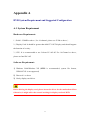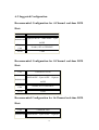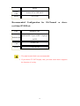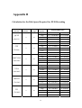
1
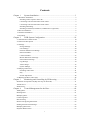
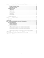
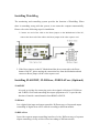
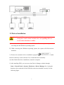
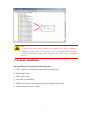
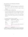
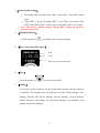
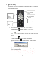
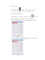
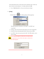
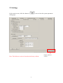
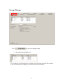
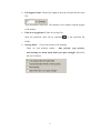
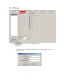
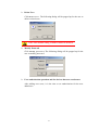
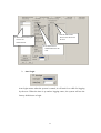
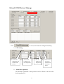
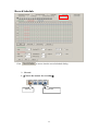
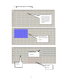
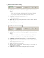
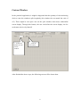
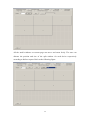
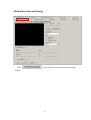
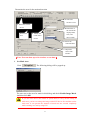
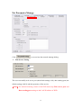
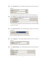
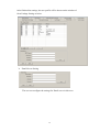
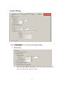
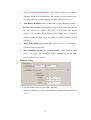
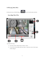
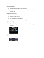
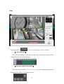
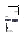
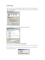
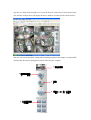
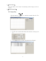
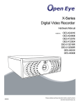
User Manual Contents Chapter 1 System Installation.................................................................................3 1.1 Hardware Installation ..........................................................................................................3 Installing Video Capture Card to PC.................................................................................3 Connecting GX-104 with Video/Audio Cable ..................................................................3 Connecting GX-108 with Video/Audio Cable ..................................................................4 Installing WatchDog..........................................................................................................5 Installing J2-485NET, J2-DIOxxx, J2-RELAYxxx (Optional) .........................................5 1.2 Driver Installation ...............................................................................................................6 1.3 Software Installation ...........................................................................................................7 1.4 Uninstall ..............................................................................................................................9 Chapter 2 DVR System Configuration.................................................................10 2.1 Introduction of Main Screen .............................................................................................10 2.2 Functions Description .......................................................................................................12 2.3 Settings..............................................................................................................................17 Storage Manage...............................................................................................................18 User Manage ...................................................................................................................20 Extend-COM Devices Manage .......................................................................................23 Record Schedule .............................................................................................................24 Custom Window .............................................................................................................27 Motion Detection and Image...........................................................................................30 Net Parameter Manage....................................................................................................32 Log Manage ....................................................................................................................34 Alert Linkage ..................................................................................................................35 System Manage ...............................................................................................................39 2.4 Playing Video Files ...........................................................................................................41 Searching Video Files......................................................................................................41 Play .................................................................................................................................43 Screen Adjustment ..........................................................................................................46 2.5 Backup and Print Video Files............................................................................................48 Chapter 3 Monitoring and Controlling by IE Browsing.......................................51 Resolution for Dynamic IP (Skip this step for Fixed IP) ........................................................51 Virtual Server ..........................................................................................................................52 IE Browsing ............................................................................................................................54 Chapter 4 Central Management for the Host........................................................60 Adding Host ............................................................................................................................61 Deleting Host ..........................................................................................................................61 Modifying Host .......................................................................................................................62 Connecting Host......................................................................................................................63 Disconnecting..........................................................................................................................64 Remote Configuring Parameters .............................................................................................65 Sending the Real-time Message ..............................................................................................65 Modifying Host Time..............................................................................................................66 Playback Remote Files............................................................................................................67 1 Chapter 5 Remote Control Mode with Central Monitor.......................................68 5.1 Remote Multi-Screen Monitor ..........................................................................................68 Multiple Split-Window Switch .......................................................................................69 Remote Pan-tilt Control ..................................................................................................69 5.2 E-Map Monitoring ............................................................................................................70 Adding Layer ..................................................................................................................70 Opening Layer.................................................................................................................71 Deleting Layer.................................................................................................................71 Modifying Layer .............................................................................................................72 Closing Layer..................................................................................................................72 Editing E-Map.................................................................................................................72 5.3 E-Map Configuration ........................................................................................................75 Chapter 6 Channel Control ...................................................................................76 Start Preview ...........................................................................................................................76 Stop Preview ...........................................................................................................................76 Appendix A ..................................................................................................................77 DVR System Requirement and Suggested Configuration ...........................................77 A.1 System Requirement ........................................................................................................77 Hardware Requirement: ..................................................................................................77 Software Requirement:....................................................................................................77 A.2 Suggested Configuration ..................................................................................................78 Recommended Configuration for 4-Channel real-time DVR Host:................................78 Recommended Configuration for 8-Channel real-time DVR Host:................................78 Recommended Configuration for 16-Channel real-time DVR Host:..............................78 Recommended Configuration for 20-Channel or above real-time DVR Host: ...............79 Appendix B ..................................................................................................................80 Calculation for the Disk Space Required for DVR Recording ....................................80 Appendix C Q & A.................................................................................................82 2 Chapter 1 System Installation 1.1 Hardware Installation Installing Video Capture Card to PC 1. Turn off the power of the computer. 2. Open the cover of the computer. 3. Insert one or several video capture card into the PCI slots and fasten them with screws. 4. Close the cover of the computer. 5. Turn on the computer. In general, after powering on the computer, Windows (the operating system) will find out the hardware of multi-image controller automatically and prompts you to install. Please cancel this window and click Driver Installation. If the hardware is not detected, it might be that the card is not inserted well or the card is damaged. Please reinsert the card or contact with the dealer. Connecting GX-104 with Video/Audio Cable 3 Connecting GX-108 with Video/Audio Cable 4 Installing WatchDog The monitoring and controlling system provides the function of WatchDog. When there is something wrong with the system, it can restart the computer automatically. Please refer to the following steps for installation. 1. Connect one end of the cable to the Reset jumper on the Motherboard of the PC; connect the other end of the cable to the Reset jumper of the video capture card. 2. If the Reset jumper on the PC Motherboard has been connected to the Reset button of the PC, please unplug the connection line from the Motherboard and connect to Reset jumper on the video capture card. Installing J2-485NET, J2-DIOxxx, J2-RELAYxxx (Optional) J2-485NET It is used as a bridge for connecting series alert signals collection of J2-DIOxxx and J2-RELAYxxx and controlling the output equipment to PC. It provides the function of interface transformation from RS485 to RS232. J2-DIOxxx It is a digital alert input and output controller. Different ways of input and output controlling of digital alert will be offered according to different models. J2-RELAYxxx It provides separate output controlling interface of relay. Different ways of separate output controlling of relay will be offered according to different models. 5 1.2 Driver Installation Note: If your DVR computer has been installed other image compression card, please remove them and delete the corresponding driver to avoid software/hardware conflict. 1) Insert the video capture card into the PCI slot. Power on your computer for accessing into the Windows operating system. 2) While accessing into Windows operating system, the system will find out new hardware. 3) Execute the automatic driver installation program under the driver directory on the software CD, or install the driver manually. 4) After finished the driver installation, restart the computer. 5) After installing DVR, you can access into Device Manager window through Start---Control Panel---System---Hardware---Device Manager for viewing the hardware driver and check if the DVR driver has been installed correctly. See the following figure. 6 Driver for Video Capture Note: If the drivers have been installed successfully, the Device Manager window would be shown as the above. The corresponding drivers used currently for different usage will be displayed with “Saa713xPCI Card WDM Driver”. 1.3 Software Installation The installation CD contains the following items: 1、Video Capture Card (depends on the model you purchase) 2、BNC Image Cable 3、BNC Audio Cable 4、One cable for WatchDog 5、DVR System and Central Monitoring & Controlling Software CD 6、Smedia GX Series User’s Guide 7 Please install software system by following the steps listed below: 1、 DVR System Software DVR system software is installed in the host with the video capture card. The software installation is simple. Execute SDVRSetup.exe under DVR system software directory and follow the onscreen instruction to complete the software installation. 2、 Central Monitoring and Controlling Software The central monitoring and controlling software is installed in the host of central monitoring and controlling software on LAN. The standard version of central monitoring and controlling software provides the capability of managing 32 packages of DVR controlling system (512 camera screens). Before installing, please make sure your computer configuration can satisfy the minimum requests listed below: The minimum requests for the computer configuration: Operating System: Win2000 Professional,Win XP Central Processor: Pentium 4,2.6G,800MHz FSB RAM: 2 * 256 Dual DDR400 DRAM Hard Disk: 200GB Display Card: NVIDIA Geforce4 MMX400 64MB, resolution 1024 * 768 Note: TVOUT display card must support the function of overlay. Network: 100M, TCP / IP It is easy to install the software. Simply execute CMSSetup.exe under the DVR software directory and follow the onscreen prompts to finish the software installation. 8 1.4 Uninstall Uninstalling software is a contrary procedure for installing software. Re-execute the installation program and choose uninstall. Or remove the program by using Add or Remove Program under Control Panel. Note: When you use installation program to uninstall the program, please notice that the directories created by users will not be deleted automatically. These directories must be deleted manually. 9 Chapter 2 DVR System Configuration 2.1 Introduction of Main Screen 4 2 Cam 3 Alarm Rec Timer Rec 5 6 7 10 8 1 9 10 Item Name Description 1 Selection of split-screen Select the number of the screen for (depends on model) monitoring,1,4,6,9,10,13,16,25,32, or choose user-defined split-screen or full screen. 2 Name of the camera Display the name of the camera 3 Record status of the Alarm REC means recording when alarm occurs; Timer camera REC means reserved recording. When choosing Alarm REC and Timer REC at the same time, it will be Timer REC when there is no alarm occurs; and be Alarm REC when an alarm occurs. 4 Minimum button A button for minimizing the screen. 5 Date, time, hard disk Display current time, date and remaining hard disk space. space 6 Play Play the video file. 7 Setup Configure the execution parameters and operation function of the system. 8 Pan-tilt Control Control the movement of pan-tilt, adjustment of camera, and the default point of pan-tilt operation. 9 Exit Click this button to choose the functions of login, logout, exit or system lock. 10 District movement It means the movement detection alert happened on this detection alert area. Note: 1. This manual takes 16 video files as the examples, so the split screens are 16 only at most. 2. The preset resolution for each camera is 320*240. 11 2.2 Functions Description 1、【Selections for Split Screen】 ¾ You can set up to 16 screens(1,4,6,9,10,13,16 and full screen) ¾ Full Screen Click the button of . It can hide setting area and allows you to monitor with full screen. Right click your mouse on the screen to return to original screen size. ¾ Largest Single Screen If you move your mouse to the screen and double-click left mouse button, you can enlarge the screen to the most without any reason at any time. If you want to enlarge other screens, you have to double-click left mouse button to return to the default screen. ¾ Split screen will display automatically: Access into the setting page to configure the parameter of channel-switching first. ¾ Function of right mouse button Click the right mouse button, FullScreen SnapShot will be shown on the screen. There are two selections, FullScreen and SnapShot for you to choose. 2、【Device Name】 Each camera can be changed for your necessity. Open the tab of “Motion Detection And Image” in the Setting page for modifying name of the device. 12 3、【Status for Recording】 ¾ Recording modes include Timer REC, Alarm REC, Time REC+Alarm REC. ¾ Timer REC is green and Alarm REC is red. When you choose Time REC+Alarm REC mode, it will be green Timer REC if there is no alarm. Note: The factory default setting is Alarm REC. Adjust the mode by yourself if necessary. 4 、【Minimized Button】 Click the button of to minimize the execution program. 5 、【Date, Time, Hard Disk Space】 Date Time Remaining Space for Hard Disk 6 、【Play】 Click the button of to search recorded file. 7 、【Setting】 It is used to set the parameters for the system and execution, and the functions of operation. The settings can be divided into ten items: Storage Manage, User Manage, Extend-COM Device Manage, Record Manage, Custom Window, Motion Detection And Image, Net Parameter Manage, Log Manage, Alert Manage and System Manage. 13 8 、【Pan-tilt Control】 It controls the movement of the Pan-tilt, the adjustment of device’s lens and the operation of pan-tilt preset. Control the zoom, focus, light of the device Adjust the speed of pan-tile movement Control the pan-tilt moving up/down/left/right. Auto means to cruise automatically Preset Adjustment Buttons ¾ Setting Preset(take Lilin speed dome as a exsample :) Click the button of Click and the numbers of the preset. up, down, left or right to jump to the specified preset. Click the button of to access into the Preset settings. And click the button of to set the first preset. See the following dialog. Type the name for the preset and click OK. For other presets, please follow the same procedure. P.S. Each brand of speed dome with different protocol design, please refer to its user manual of device what you purchased for operation. 14 ¾ Shift to other Preset Click the button of to display the numbers of the preset. Click any one of them to jump to the specified preset. ¾ Set Auto-Cruise and Auto-Scan After finished the preset setting, Click the button of to access into the interface of auto-plane. Refer to the following figures. ¾ Activate Auto-Plane scan: This function needs the support of pan-tilt. ¾ Activate Decoder to cruise automatically. Refer to the following figure. 15 Use the drop-down menu to select the preset for automatic cruise. Set the stay time of the preset (the minimum is 3 seconds) and then click OK. ¾ Press “Clear Preset Pos” to clear previous all preset settings. 9 、【Exit】 Click the button of . The following dialog will be popped up. The modes that users can choose are “Re-Entry”, “Exit DVR” and “Lock DVR”. ¾ Re-Entry: Choose this mode and click OK. The user must re-login DVR. ¾ Exit DVR: Choose this mode and click OK. The user can exit DVR. ¾ Lock DVR: Choose this mode and click OK. The DVR and the screen will be locked. Note: When the program is locked, the user cannot execute any operation any more till the lock status is released. See the following figure. 16 2.3 Settings On the main screen, click the button of setting page. to access into the system parameter Note: The Software version is based on the factory edition. 17 Display software version Storage Manage Click ¾ to open user manage dialog. Select the Storage Disk Area The one that is checked means the recording will be held by this disk. The one that is not checked means recording job will not be held with such disk. 18 ¾ File length of time: Choose the length of the time recorded for the video file. Type the number in this box. The shortest is five minutes; and the longest is 90 minutes. ¾ Path of saving picture: Folder for saving files Store the playback video file by snapshot to the specified file folder. ¾ Storage mode: Choose the mode for file deleting There are four deletion modes – time priority, type priority, non-cleaning and alarm when disk is not space enough? offered for the user to choose. 19 User Manage Click ¾ to access into User Manage dialog. Add User Click A dd U ser . The following dialog will be popped up for the user to add new users. 20 ¾ Delete User Click D el ete U s er . The following dialog will be popped up for the user to delete existed users. Note: The default setting of admin cannot be deleted. ¾ Modify Password Click Modify pa sswo rd . The following dialog will be popped up for the user to modify password. ¾ User authorization operation and the devices that user can browse After adding new users, it is the time to set authorization for the new added user. 21 3. Set the authorized 1. Select the user that you devices for the user to browse. want to set authorization. 2. Set the items of authorization for the user. ¾ Auto Login Auto login means when the system is started, it will wait for a while for logging by the user. When the time is up and no logging enters, the system will use the factory default user to login. 22 Extend-COM Devices Manage Click ¾ to access into hardware management dialog. PTZ Setting 1. Choose the default pan-tilt model of the factory. ¾ 2. Choose the COM port for PC and pan-tilt. 3. Set the address for the pan-tilt. 4. Set the baud rate of the transmission for the job series. Alarm Box (Optional) The detailed explanation of the operation will be offered to the user after he/she purchased it. 23 Record Schedule Click to access into the record schedule dialog. ¾ Record 1.【Choose the camera for recording】 Selected Non-selected 24 2. 【Choose the time of recording】 1. Click the left mouse button and drag the mouse on the time schedule to choose the preferred time section. 2. The selected time section will be shown in blue. 4. Timer+Alarm Record 3. Timer Record 5. Alarm Record 25 3.【Timer Recorder Parameters Setting】 ¾ Quality: There are six levels of the image quality for the user to choose, such as: NTSC: 160x120, 320x240, 640x240, 640x480, 720x240, and 720x480 PAL: 176x144, 352x288, 640x288, 640x576, 720x288, 720x576 ¾ FrameRate: The adjustable range is from 1 to 30. The default setting is 1. ¾ Image Size: There are several selections for the user to choose, such as: Highest, High, Normal, Low and Lowest. ¾ Audio: Check this box to record audio. 4. 【Alarm Recorder Parameters Setting】 ¾ Quality: There are six levels of the image quality for the user to choose, such as: NTSC: 160x120, 320x240, 640x240, 640x480, 720x240, and 720x480 PAL: 176x144, 352x288, 640x288, 640x576, 720x288, 720x576 ¾ FrameRate: The adjustable range is from 1 to 30. The default setting is 1. ¾ Image Size: There are several selections for the user to choose, such as: Highest, High, Normal, Low and Lowest. ¾ Audio: Check this box to record audio. ¾ Duration: Set the duration of the alarm. The longest is 90 seconds. The default setting is 30 seconds. PreRecord: Set the time before recording. The longest is 30 seconds. ¾ 26 Custom Window In the practical application, it might be happened that the quantity of the monitoring devices cause the windows split irregularly (the windows do not match the ratio of 4:3). There might be one space area on the split windows that causes unbeautiful screen display. Through this feature, the user can define the screen display size for each camera device by himself. 1.Select the 2.Click the number for the custom window. New button. After finished the above steps, the following screen will be shown then. 27 All the small windows on current page can move and zoom freely. The user can allocate the position and size of the split window for each device respectively according to his/her request. Refer to the following figure. 28 Press to save the customized split windows with a name. Now, the buttons on the main screen will be changed as the following: Go to main screen and click the button of custom window . Choose 5 split that defined in .DVR will display the windows according to the window setting you choose. 29 Motion Detection and Image Click to access into the motion detection and image dialog. 30 Determine the area for the motion detection 3. Select the sensitive level 1. Select the camera device 2.Draw the area 5. Determine if the record file displays date, time, and device name 4. Modify the name of the device 6. Select the video standard 7. Adjust the color of the window 【Note: You can draw up to 16 windows at one time.】 ¾ Set Mask Area Click . The following dialog will be popped up. The user can set the area for mask in this dialog and check Enable Image Mask. And then click OK. If you use PTZ device (PT camera or speed dome) to carry out the setting of mask area, you have to enlarge the image on the PTZ device first and then set the mask area. It can prevent the situation of mask area not covered completely while zooming in or out by using PTZ. 31 Net Parameter Manage Click ¾ to access into the network manage dialog. Web Server Setting The user can modify web server port (the default setting is 80), data sending port (the default setting is 8001) and the open time of the service. 【Note】For remote browsing, router of the DVR must map Web server port and Data sending port settings to the LAN IP address of DVR. 32 ¾ Limit the Traffic of the Network for DVR The user can limit the number of people (up to 32) for browsing DVR at the same time, the maximum bandwidth for the system while browsing in LAN, and the maximum bandwidth for the system while browsing in Internet. ¾ IP Filter 1. Click Add to set the range for the IP address. 2. Choose Exclude IP-Address in list or Exclude IP-Address out of list. 3. Check the box of 4. Click to open the IP address filter function. to check users who have logged in. 33 Log Manage Click ¾ to access into Log Manage dialog. According to personal requirement, the user can inquire or check System Log, Operation Log, Login Log and Alarm Log. 34 Alert Linkage Click ¾ to access into Alert Linkage dialog. Alert Linkage Setting Click . The following dialog will be popped up. 35 The user can carry out the setting of alert linkage by following Step1 to Step4. Select the Alert Linkage: Click “Record”. The available linkage parameters will be shown on the box of Linkage Device. The user can choose one of the devices for carrying out alert linkage recording. After clicking “Snapshot”, the available linkage parameters will be shown on the box of Linkage Device. The user can choose”Snapshot one picture” or “Snapshot picture number” certain period. At most, the number of the pictures that “Snapshot picture number” can be set is 30. Click Wave file. The available linkage parameters will be shown as follows: The user can load the sound file with WAV format by himself. Click “Output Control”. The available linkage parameters will be shown Note: This function only appear when a alarm box or module connects with DVR system. 36 Click “Pan-tilt Preset”. The available linkage parameters will be shown as follows: The user can choose which PTZ will be motion linked with pan-tilt preset. Click “Email”. The available linkage parameters will be shown as follows: The user can fill in destination of the email, the subject of the email and the content of the email. Click “Zoom in Preview”. The available linkage parameters will be shown as follows: The user can choose which window to be zoomed in. Click “Telephone”. The available linkage parameters will be shown as follows: Click “Phone Message”. The available linkage parameters will be shown as follows: 37 After finished the settings, the user profile will be shown on the window of Alert Linkage Setting as below. ¾ Email Server Setting The user can configure the settings for Email server in this area. 38 System Manage Click ¾ to access into system manage dialog. DVR Setting 1. Auto run with windows start-up: Execute the program automatically after accessing into the computer system. 39 2. Allow User to Access Windows: The default setting of re-entering Windows for the user is not allowed. The window will be restarted if the user closes the monitoring/managing software without permission. 3. Auto Reboot Windows:Set a certain time to restart Windows system. 4. Preview tour(seconds): Check the box of preview tour(seconds) and set the time interval for window shift with 3~120 seconds (the default setting is 15 seconds). DVR software will display next set of split windows when the time is up according to current number of split windows. 5. Make Water-Mark for record file: Check this box to prevent the rewritten of the recorded file. 6. Show SnapShot picture on preview-window: After capturing the picture, the system will display the picture automatically on the right corner of the preview-window. ¾ Windows Setting 1. Set the modification of system date and time. 2. Set the modification of network IP address, subnet mask, gateway and so on. 40 2.4 Playing Video Files On the main screen, click the button of to access into the player interface. Searching Video Files 4 5 2 1 3 1.【Camera device】 ¾ Select the Camera number that you want to search ¾ If you click on the number that you want to search, the color of the button will be changed. 41 2.【Time Indication】 ¾ It can indicate the time that the data was stored. ¾ When you click these buttons, you can clearly know the range for the recording time. 3.【Storage Time Indication】 This function can indicate the type and time of the recording. ¾ Green means Timer Record ¾ Red means Motion Detection Record ¾ Long bar without any color means no recording 4.【Date Selection】 ¾ If there is recording files existed, the color of that date will be changed as the following. 5.【Time Selection】 ¾ Precise time configuration can be set with minute. 42 Play Click the button of ¾ to access into the searching screen of video files. 【Camera Selection】 If you click the number of camera device, the color of the represented one will be changed. Refer to the following figure. ¾ 【Setting the Split-Window Mode】 The split-window modes (1、4、6、9、10、13、16) will be adjusted automatically according to the number of the camera devices. 43 Number of the Selected Split-Window Devices ¾ 1 Full Screen 1-4 4 Split-Window 1-6 6 Split-Window 1-9 9 Split-Window 1-10 10 Split-Window 1-13 13 Split-Window 1-16 16 Split-Window 【Play】 You can use Fast Speed Play, Slow Speed Play, and Time to control the speed of video playing. Play Go to the end point of the selected date Go to the start point of the selected date Play forward Play backward Play the next picture Play the previous picture 44 Slow / Fast Fast Speed includes the times of 1,2,3,4 and 8. Slow Speed includes 1/2,1/4 and 1/8 .The times for the fast play will be different according to the split-window setting. Number of devices that the The highest times for play the fast play simultaneously 1 8 times 2 4 times 3 2 times 4 2 times 5 or above 1 time Play the audio ¾ 【Recording File Saved as AVI for Playing】 After saved the recording file with AVI format, a plug-in object will be created automatically. Before playing AVI file for the first time, you have to install such plug-in first. 45 Screen Adjustment Click the button of on the top-right side of the window to adjust the brightness, contrast, softness, flip, rotation of the image and retrieve factory default setting. ¾ 【Functions】 【Brightness】This function is used to adjust the brightness of the image 【Contrast】This function is used to adjust the contrast of the image 【Softness】This function is used to soften sharpened image 【Flip】This function is used to flip image 【Rotate】This function is used to rotate the image with 90,180 and 270 degree 【Reset to Default Setting】This function is used to retrieve the default settings for all the parameters. 46 ¾ 【Zoom In Partially】 Use the right mouse button to frame the area that you want to zoom in. The area inside the frame will be enlarged immediately. The following is a zoom-in image within green frame of the above figure. 47 2.5 Backup and Print Video Files ¾ 【Convert AVI】 Click the button of . The Convert AVI window will appear. Choose the preferred channel and determine the time and date for the convert. Then, click “Search”. The result will be shown as the following. Use the mouse to select the one that you want to convert and click 48 to transfer the selected file into right frame. See the figure below for reference. Click the button of . The system will prompt you to choose the position of the convert. After choosing a proper one, the AVI file convert will be carried out and save to the folder path you appoint. 49 Click the converted AVI file. It will be played directly as shown below ¾ 【Print】 Click the button of . The software will search the default printer and print current image played on the window. ¾ 【Snapshot】 Click the button of . The captured image will be saved under the folder that created in Storage Manage setting page. ¾ 【Lock】 Click the button of . The video image played on the window will be displayed with single window but not split-window. Click once again , the video image will be back to original display image. ¾ 【Zoom In Gradually】 Click the button of . Certain part of the image that you want to browse will be enlarged gradually. 50 Chapter 3 Monitoring and Controlling by IE Browsing To experiment the remote control through Internet, please refer to the following procedure. Resolution for Dynamic IP (Skip this step for Fixed IP) Each time, a temporary public IP will be assigned to ADSL for accessing Internet through dial-in. For such public IP is dynamic, it will bring certain trouble to remote monitoring. At this time, the user can apply dynamic function variation name and download software for client for such function. There are many websites which offer dynamic function variation such as www.comext.cn, www.oray.net, etc. With such name, the user does not need to memorize or inquire the dynamic IP address all the time. The application for the name of dynamic function variation, name for the dynamic function variation and the judging procedure for the IP address of DVR server will be explained detail in the websites. We take www.comexe.cn as an example. The general steps are listed as below: 1)Apply the name for the dynamic function variation, e.g., xddns.dns0755.net 2)Download the software for the client of the dynamic function variation , 3)Execute and set the software of client in DVR computer (please type in the functional variation that you applied, ID and password) 4)In DOS prompt of the system, please ping if the name of the functional variation bind with public IP. If the IP displayed on the screen is the same as your public IP, it means that the bind operation is successful. Public IP 51 Virtual Server The internal computers in LAN do not have public IP address but have private IP such as 192.168.0.2. Such IP cannot be used to access into Internet directly. At present, ADSL is very popular. Most of the companies or individuals can browse Internet through the following steps. Way 1: Telephone Line—ADSL adapter--router--hub--computer (for the network security of DVR system, it is recommended to use router as the firewall) Way 2: Telephone Line --ADSL adapter -- computer If you use Way 1 for connecting Internet, it is necessary for you to adjust router settings to manage hard disk recording for the remote computer. With configuring virtual server, all the data passing from the communication port (default is 8001) of hard disk recording will be transferred to the computer through the router. Thus, the external network can be browsed through the IP address of the router and managed remotely by Internet. Also, the port number, 80 must be virtual. As to the settings for router, please refer to the user’s manual for detail information. Now, we take TP-LINK router as an example and explain the way to set virtual server briefly: press Internet Explorer on the desktop of the Window; op3n IE browser and type 192.168.0.1, Later you will see the following dialog. Type the username and password to access into the main page of the router. Set transportation for the port 80 and 8001 (suppose the internal IP address for hard disk recorder is 192.168.0.200) and save the settings. Next, restart the router. 52 Note: The port number used for virtual IP must the same as set in Network Manage. Refer to the following figure. 53 IE Browsing First, you have to set activation plug-in manually. Open the IE browser and go to Tool – Internet Options. In the Internet Options window, select the tab of Security. See the figure below. Click Custom Level... The following dialog will be popped up. Check all the boxes for ActiveX controls and plug-ins. In the address line of IE browser, type IP address of DVR server or the name of dynamic function variation (if it is in LAN, type LAN IP address in the column of IE address). The following dialog will appear. 54 Type the user name and password to access into IE browser (client end). The left menu on the user interface of IE browser will display the device number of remote DVR as shown below: The user can execute playback, setting and controlling pan-tilt for the images on remote DVR monitored by IE browser through the network with using the computer. 1. 攝影機選擇 2. 播放錄影畫面 3. 設定 5. 雲臺上、下、左、右控制 4. 分割畫面選擇 55 1、【Select Camera】 Select the number of the Camera for monitoring real-time images on the site remotely. 2、【Play the Video File】 Remote Play Click the button of to search the recorded video file. The following screen will appear. ¾ The file can be searched with channel, date and time, record type, and etc. ¾ Click SEARCH. The files under certain directories will appear. 56 ¾ Select the file you want. Click the button of the button of to start playing; and click to stop playing. A single file is played, a single window will be shown. Two or more files are played, multi-window will be shown. 57 Download Remotely Click Start Download to store the searched video file (.bmp) to the specified folder, e.g., D:\DVR Capture\20060811. Then, the downloading begins and the completion percentage of downloading will be shown as the following: Play After Download Remotely Select the file to play from the folder that stored the download files. Next, the downloaded image file will be played with Media Player. 58 3、【Setting】 It is used to set the parameters for the system and execution, and the functions of operation. The settings are allowed to use for ten items: Storage Manage, User Manage, Extend-COM Device Manage, Record Manage, Motion Detection And Image, Net Parameter Manage, Log Manage and System Manage. Note: For the detailed information about setting, please refer to Chapter 2, section 2-3. 59 Chapter 4 Central Management for the Host The central management software (CMS) can manage multiple monitoring systems through one interface and allows the administrator to manage multiple monitoring hosts (up to 32 DVR devices) on one place at the same time. CMS is installed in the monitoring host on Internet or Intranet. The standard version of CMS has the capability of managing 32 DVR systems at one time (512 screens). Before installing the software, please make sure your computer equipment can fit the following minimum requirements. The minimum request of computer equipment: Operation System: Win2000 Professional,Win XP CPU: Pentium 4,2.6G,800MHz FSB RAM: 2 * 256 Dual DDR400 DRAM Hard Disk: 250GB (suggested) Display Card: NVIDIA Geforce4 MMX400 64MB, resolution 1024 * 768 Note: TVOUT display card must support the function of overlay. Network: 100M network, TCP / IP The software installation is easy. Simply execute CMSSetup.exe under the DVR software directory. Follow the onscreen prompts to finish the software installation. There are two managing modes provided here. 1. Split-Window Monitoring Mode 2. E-Map Monitoring Mode The host management is to add, modify, delete, connect, disconnect remote hosts via network and the set the functions of the hosts. 60 Adding Host Press the Host menu bar or the host list frame and click the right mouse button. The Host Manage menu bar will appear. Choose “Add Host” to open the following dialog and type the relational information of DVR host. Host name of remote DVR Username and password for browsing that host Press “OK” to add a new host in the host list (as figure: DVR). Deleting Host In the host list, choose the one that you want to delete and click the right mouse button. 61 Choose “Delete Host”. The following dialog will appear. Press “Yes “ to delete that host. Modifying Host In the host list, choose the one that you want to modify and click the right mouse button. Choose” Modify Host” to change the name of the host or the connection parameters. 62 Connecting Host On the new added host(e.g,DVR host),click the right mouse button and select “Connect”. The icon of will blink continuously to indicate connecting. After connected successfully, all the channels (Cam1,Cam2…)of that host will be listed under the host. If you want to see a real-time image for certain channel, you can click right mouse button on the channel and choose “ Start Preview” . Then, the monitoring window on the left side will show the real-time image. 63 Disconnecting In the host list, choose the host that you want to disconnect and click the right mouse button. Then select “Disconnect”. The CMS software will disconnect the link of that host. 64 Remote Configuring Parameters This menu allows you to set the parameters for the DVR host remotely on the central monitoring host. In the host list, choose the host that you want to configure and click the right mouse button. Then choose “Remote Config”. Then, Remote Config dialog will appear. The settings are allowed to config eight items: Storage Manage, User Manage, Extend-COM Device Manage, Record Manage, Motion Detection And Image, Net Parameter Manage, Log Manage and System Manage. Note: For the detailed information about setting, please refer to Chapter 2, section 2-3. Sending the Real-time Message The operator of central monitoring can communicate with the members in DVR host remotely. In the host list, choose the host that you want to configure and click the right mouse button. Then select “Send Contacts” . 65 Later, a dialog will be popped up. ¾ The message transmitted from central monitoring room to the DVR host. After input message, it will be shown on this box. Input message ¾ The message received by DVR host from central monitoring room . Modifying Host Time This function is used for correction between DVR host and central monitoring host. In host list, choose the one that you want to configure and click the right mouse button. Then choose “Modify Host Time”. 66 Then, the following dialog will appear. After pressing “Yes”, the time will be simultaneous with the time of the remote central monitoring host. Playback Remote Files This menu can playback the video information on the DVR host in the central monitoring host remotely. In the host list, select the host for playback video file and click right mouse button. Then choose “Remote Playback”. Then the following playback screen will appear. Note: For the detailed information about playing video file, please refer to Chapter 2,section 2-4. 67 Chapter 5 Remote Control Mode with Central Monitor 5.1 Remote Multi-Screen Monitor Host List Pan-tilt Control Split-Window Display Area Function Switch Click the right mouse button on the split-window. The above screen will appear. 68 Multiple Split-Window Switch Click the right mouse button on the split-window, then select the split-window to experiment monitoring multi-channel screens to DVR host. Remote Pan-tilt Control Carry out “Start Preview “ to the channel of the pan-tilt that you want to control. If that channel is equipped with pan-tilt, the screen of remote pan-tilt control will appear. Pan-tilt control for up, down, left, right, turning on and off. AUTO means to activate automatic cruise function. Zoom in/out, focus, light control to the camera device Setting and adjustment of preset Preset In this interface, it can experiment controlling current connected host for choosing screens to map the operation of up, down, automatic cruise, preset with remote pan-tilt of the device. 69 5.2 E-Map Monitoring Click button of Function Switch and choose E-Map. The E-Map window will appear. Adding Layer Click right mouse button to choose “Add Layer”on the display window of the E-Map. The Layer dialog box will appear. Type the name or the description for the new layer and choose the background picture for the new layer (bmp or jpg). And then click OK. 70 Opening Layer From the list areas of the E-MAP, choose the map that you want to see and click “Open Layer” menu. The e-map of the selected layer will be shown on the display window of E-Map. Deleting Layer Click right mouse button to choose” Delete Layer”. The dialog will appear as follows: Click” Yes” to delete the sub-map of the selected layer. 71 Modifying Layer Click right mouse button to choose “Modify Layer”. A dialog will appear for you to modify the name of the sub-map. Closing Layer From the list areas of the E-MAP, choose the map that you want to close and click “Close Layer” menu. The e-map on the selected layer will be closed. Editing E-Map Click right mouse button to choose “Edit E-Map” to access into the edit mode. 72 (1)Add a Device Icon to the Map You can drag the device icon from the host list to the e-map. Also you can drag the device icon from the floating tool bar to the e-map. In the popped up window, click “OK”. (2)Add an Alarm Icon to the Map You can drag the alarm icon from the floating tool bar to the e-map. And in the popped up window, please type the name of the alarm and the address of the alarm. 73 (3)Delete the Objects on the E-Map In the Edit-Emap mode, you can click right mouse button to choose “Delete “ for deleting objects. (4)Finish the Editing Close the floating tool bar or uncheck the “Edit E-Map” menu item to exit the editing mode of the system. 74 Double click the icon of device (camera) to view the real-time image of that device. 5.3 E-Map Configuration Press the button of Functions Switch and choose “Local Config” menu. The following window will appear. All the default alarm icons and device icons that users can choose and load freely for editing the e-map will be displayed. 75 Chapter 6 Channel Control This menu allows you to configure and control the working status for the device (camera) of each channel that connected to the host. At present, there are two controls provided here. Start Preview To view a real-time for certain camera device, you can move your mouse to the selected device and click right mouse button for choosing “Start Preview”. Later, the real-time image will be shown on the left side of the monitoring window. Stop Preview Click the right mouse button on the selected channel and choose “Stop Preview”. Later, the image on the split-window corresponds to the selected channel will be closed. 76 Appendix A DVR System Requirement and Suggested Configuration A.1 System Requirement Hardware Requirement: 1)RAM:256MB or above(for 16-channel, please use 512M or above). 2)Display Card: It should be greater than 64M. TV-OUT display card should support the function of overlay. 3)CPU: It is recommended to use Celeron D 2.4/2.8G. For 16-Channel or above, please use Intel P4 2.4G Software Requirement: 1) Windows 2000/Windows XP (NTFS is recommended; system file format; WIN98/97/95 is not supported) 2) Directx 8.1 or above 3) Newly display card driver Before driving the display card, please insert the driver for the motherboard first. Otherwise, it might affect the normal working for display card and DVR. 77 A.2 Suggested Configuration Recommended Configuration for 4-Channel real-time DVR Host: CPU Motherboard Celeron 4 1.7G Gigabyte 845GE、AMD 845PE、Epox 845PE Display Card Seethru, ATI or GEFORCE RAM 128M Recommended Configuration for 8-Channel real-time DVR Host: CPU Celeron D 2.4-2.8G AMD 865PE、Epox 865PE、Gigabyte Motherboard 865PE Display Card Seethru, ATI or GEFORCE RAM 256M Recommended Configuration for 16-Channel real-time DVR Host: CPU Celeron D 2.8G Motherboard AMD 865PE、Epox 865PE、Gigabyte 78 865PE Display Card Seethru,ATI or GEFORCE RAM 256-512M Recommended Configuration for 20-Channel or above real-time DVR Host: CPU Pentium 4 2.4G AMD 865PE、Epox 865PE、Gigabyte Motherboard 865PE Display Card Seethru, ATI RAM 512M DDR400 1. The main board of 848 is not recommended. 2. If you choose TV-OUT display card, you must ensure that is supports the function of overlay. 79 Appendix B Calculation for the Disk Space Required for DVR Recording Recording Format Number of Channel Recording Images QCIF 4 25 (160*120) CIF 4 25 (352*288) Half-VGA 4 25 (640*240) VGA 4 25 (640*480) Half-D1 4 25 (720*240) D1 (720*480) 4 25 Recording Quality Required Disk Space Highest 300—500M/Hour 6.5--13G/day High 167—334 M/Hour 3.9--7.8G/day Middle 133—267 M/Hour 3.1--6.2G/day Low 68—137 M/Hour 1.6--3.2G/day Lowest 53—106 M/Hour 1.2--2.5G/day Highest 0.7--1.4 G/Hour 17--34G/day High 0.4--1.3 G/Hour 10--20G/day Middle 213--426M/Hour 5--10G/day Low 173--346M/Hour 4--8G/day Lowest 90--180M/Hour 2.1--4.2G/day Highest 2—4G/Hour 48—96G/day High 0.9—1.8G/Hour 21—42G/day Middle 0.6—1.2G/Hour 14—28G/day Low 0.4—0.8G/Hour 10—20G/day Lowest 149—300M/Hour 4—8G/day Highest 2—4G/Hour 48—96G/day High 0.9—1.8G/Hour 21—42G/day Middle 0.6—1.2G/Hour 14—28G/day Low 0.4—0.8G/Hour 10—20G/day Lowest 149—300M/Hour 4—8G/day Highest 2--4G/Hour 48--96G/day High 0.9--1.8G/Hour 21--42G/day Middle 0.6--1.2G/Hour 14--28G/day Low 0.4--0.8G/Hour 10--20G/day Lowest 149--300M/Hour 4--8G/day Highest 2--4G/Hour 48--96G/day High 0.9--1.8G/Hour 21--42G/day Middle 0.6--1.2G/Hour 14--28G/day Low 0.4--0.8G/Hour 10--20G/day Lowest 149--300M/Hour 4--8G/day 80 Note: 1、If the quantity of image recorded for every second is reduced, the data will be down also. For example, if the recording quantity is 12pcs/sec, the data will be down half. The A.F always is 10M/hour. 2、The above calculation of disk space is the test result done in a lab. It is just for user reference. The concrete recording data, quality of the front-end device (camera) and the monitoring screen will be changed according to the practical movement degree. 81 Appendix C Q&A Q:When I insert DVR card and power on the computer, I cannot access into Windows. Why? A: It might be caused by damaged card or the card is not compatible with the motherboard. You can change a new DVR card to do the test. If the situation is still the same, then it must be the DVR card incompatible with Motherboard. Please change another Motherboard. We suggest you to use Gigabyte 965E or any card with famous brand. Q: After powering of the computer and executing DVR software, the system will be down A: The possible reasons might be 1) the card is damaged; 2) the card is not compatible with the Motherboard; 3) the card is not compatible with Windows XP and Motherboard. The possible resolutions can be: First, make a test with other Ether DVR card. If the problem still exists, the reason of damaged card can be removed. Next, uninstall Windows XP and install Windows 200 and redo the test. If the problem still exists, it can be sure that the Motherboard is not compatible with the DVR card. If the problem can be solved by changing the operation system, then it can be sure that the DVR driver is too old. Please contact with your dealer as soon as possible to have the updated driver. Q:DVR system can execute and display the image but the motion is too slow. In addition, the mouse movement also is very slow. A: It might be caused by the limitation of CPU. To solve this problem: 1. Reduce the recoding images of the screen. 2. Replace a better CPU suggested by this manual 82 Q: After activating DVR software, a gray screen will appear. Yet the recording is normal. A: Such problem is caused due to the incompatible display card. Replace another display card, please. Q: The port number of 80 is occupied by other device. What can I do? A: Change the port number 80 to another number. For example, you can change the port number 80 to 81 for the public IP:211.97.48.12. Simply type http://211.97.48.12:8002 for browsing that network. Q: Plug-in driver cannot be downloaded while browsing through IE. What can I do? A: It is caused due to the firewall or small program (e.g., 3721) installed on your computer. If your computer has installed firewall, you can configure the firewall to let the IP browsed by Internet be trusted by your computer. If your computer has the program like 3721 installed, please click “Install ActiveX plug-in” after you open IE browser and type the IP address (LAN or Internet address, a prompt will appear for you to click). 83