1
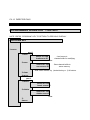
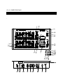
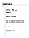
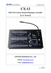
DIGITAL DMX
PROGRAMMABLE DIMMING CONSOLE
DIRECTOR PLUS
CX-12
USER MANUAL
VERSION 2.02
CX-12 DIRECTOR PLUS
CONTENT
1)
BRIEF OPERATION DESCRIPTION
STARTING CHANNEL OPERATION…………………………………1
CREATING A SCENE............................................................................ 3
OPERATING A SCENE ......................................................................... 4
SETTIING UP A SEQUENCE............................................................... 5
OPERATING CHASE............................................................................. 6
A/B CROSS FADERS ............................................................................ 7
2)
MAIN FUNCTIONS .............................................................................................. 8
3)
SETUP OPERATION (FLOW CHART)............................................................ 9
4)
SEQUENCE OPERATION (FLOW CHART)................................................... 10
5)
GENERAL FUNCTIONS
PRODUCT ILLUSTRATION...................................................................... 12
PRODUCT DESCRIPTION........................................................................ 13
6)
SYSTEM CONFIGURATION................................................................................ 15
7)
8)
SPECIFICATION .................................................................................................... 16
MAINTENANCE ..................................................................................................... 16
CX-12 DIRECTOR PLUS
OPERATING DESCRIPTION....…….Starting channel operation
A. POWER SUPPLY:
110V~240V AC
B. TURNING POWER ON;
Hardware ac on / off switch on rear panel
software; on/off switch on upper right corner of front panel
C. BLANK KEY; check led light on blank key. Cx-12 is operational
when when light is off.
D. CHANNEL OPERATION
1. Pull down all the fader VR---->to the bottom
2. Pull down master fader VR---->to the bottom, then press key below.
3. Adjust master faderVR to maxium level.
4. Press SC/CH key to enter into channel mode-----> LCD shows:
PAGE START CH01
Check if operation is in Channel mode (2 ways);
1. LCD screen
2. page keys’indication lights: green = channels, red = scene
5. Press page key #1~4, depending on start channel of first fader VR (see below) .
6. Page 1,2,3,4 --> page 1: ch01~24---> LCD shows: PAGE START CH01
page 2: ch25~48---> LCD shows: PAGE START CH25
page 3: ch49~72---> LCD shows: PAGE START CH49
page 4: ch73~96---> LCD shows: PAGE START CH73
CX-12 DIRECTOR PLUS
Example: How to set the level of the following channels;
Ch#25------70%
Ch#26------50%
Ch#01------100% (fl)
Ch#95------90%
Steps :
1. Press page 2 (ch25~48) ------>LCD:PAGE START CH25
2. Adjust fader VR #1 to 70% (LCD shows channel level)
3. Adjust fader VR #2to 50% (LCD shows channel level)
4. Press page 1 (ch01~24) ------>LCD shows :PAGE START CH01
5. Adjust fader VR #1, and #2 to 0% -bottom (LCD shows channel level)
note: ch25 &ch26 will remain unchanged.
6. Adjust fader VR #1 to 100% (fl)
7. Press page 4(ch73~96) ------>LCD: PAGE START CH73
8. Adjust fader VR #1 to 0%
9. Adjust fader VR #23 to 90% (LCD shows channel level)
P.s. : if you want to change the level of ch26 to 40%;
1. Press page 2 (ch25~48) ------>LCD:PAGE START CH25
2. Adjust fader VR #23 to 0%
3. Adjust fader VR #2 to 100%, then down to 40%
TO SET CHANNEL LEVEL TO A SCENE, SEE NEXT PAGE
CX-12 DIRECTOR PLUS
OPERATING DESCRIPTION................. Creating a scene
A A scene can only be created through the set of channels. See channel operation,
or the following example.
B. Set the level of channels desired.
C. Save channels to a scene No.
1. Press PROG key------------>LCD shows: 1.Scene 2. Sequence
2. press function key #1(Scene) -----> LCD shows: 1.Load 2.Save 3.Clear 4.More
3. Press function key #2 (Save)
4. Key in the desired scene No. to be saved
(choose from 01~96 on the number keys)
5. Press enter. Scene is displayed
Example: Create scene #1 with the following channels
CH1=100%
CH12=100%
CH11=100%
CH12=100%
CH15~18=100%
CH25~30=100%
STEPS
1. Adjust master fader VR to 100%
Make sure the program is in CH mode (see LCD screen), if not press the SC/CH
key.
2. Press page #1----->LCD shows: PAGE START CH01
3. Adjust fader VR #1,2,11,12,15~18 to 100%
4. Press page #2----->LCD shows: PAGE START CH25
5. Adjust fader VR #1,2,11,15~18 to 0% - bottom
6. Adjust fader VR #1~6 (CH25~30) to 100%
To save channels’ level to scene No.;
7 .Press PROG key-----> LCD shows:1.Scene 2.Sequence
8. Press function key #1(Scene)-----> LCD shows :1. Load 2. Save 3. Clear 4. More
9. Press function key #2. (Save)--->LCD shows: SAVE SCENE 01
10. Press desired scene #................................. press key numbers #0 and #1
11. Press ENTER. All pevious channels are now saved in scene #1 (sc-1)
12. Continue as described above to create up to 96 scenes.
CX-12 DIRECTOR PLUS
OPERATING DESCRIPTION...................... Operating a scene
Scene can be recalled by:
a. Using keys to load scene #
b. Using fader vr to load scene #
A. USING KEYS TO LOAD SCENE #
First adjust all faderVR to 0%
1. Adjust all channel levels to 0% by adjusting master vr to 0%, then pressing
the master key (under the master fader vr)
2. Adjust master vr to 100%
3. Press PROG key ----------->LCD shows: 1. Scene 2. Sequence
4. Press function key#1 (Scene)----> LCD shows 1. Load 2. Save
3.Clear 4.More
5. Press function key#1 (Load)----> LCD shows ; LOAD SCENE 01
6. Press number keys #0, and #1
7. Press ENTER. Scene #01 is now loaded.
B. USING FADER VR TO LOAD SCENE #
1. Adjust all channel levels to 0% by adjusting master vr to 0%, then pressing
the master key (under the master fader vr)
2. Adjust master vr to 100%
3. Press SC/CH key. Red light on page key indicates scene mode. (green light
indicates channel mode) ----->LCD shows: PAGE START SC01.
4. Press PAGE 1 key (faders VR#1~24 = Scenes: SC01~SC24).
5. Adjust fader VR #1 to 100%.
CX-12 DIRECTOR PLUS
OPERATING DESCRIPTION.........Setting up a sequence
Setting a sequence provides the operation for both the chaser and the A/B
crossfaders.
A A sequence can be made only when more than two scenes have been set.
B. Prog--------------->Scene
å ---->Sequence ---------------->Chaser program (for chaser)
å ------>A/B Cross fader
C. Set scene in advance
D. Create a sequence with the scenes.
Note:Squence programs are used to run chaser program or for the A/B cross fader.
1. Press PROG key-------->LCD shows: 1. Scene 2. Sequence
2. Press Function key #2(Sequence)---------->LCD shows: 1. Load 2. Save
3.Edit 4.Clear
3. Press function key #3 (Edit) ---------> LCD shows : 1.:1 2:+ 3:- 4:E
4. LCD also shows : Sequ.Step01=S(scene)00
A. Key in a desired scene#, previously saved, to step #01.
B. Press ENTER. LCD shows--------> Sequ.Step02=S(scene)00
C. Step#2 is now ready to be entered.
D. Key in a desired scene#, previously saved, to step #02.
E. Press ENTER. LCD shows--------> Sequ.Step03=S(scene)00
F. Step#3 is now ready to be entered.
G. To end sequence: press function #4(E-end)
Note: there are a total of 64 steps possible
5. To save: indicate a # to the sequence program.
A. Press PROG--------->LCD shows: 1.Load 2.Save 3.Edit 4.Clear
B. Press function key #2 (Save)
C. Press a No. (01~24) . Example: No. 04
D. Press ENTER. The sequence has been stored in No. 04
CX-12 DIRECTOR PLUS
OPERATING DESCRIPTION.............Operating chase
Recall a sequence program to operate chase
A. Press CHASER key-------->LCD shows: SELECT:F01.....F24
B. Use No. keys (01~24), to select sequence program.
C. Press ENTER
D. Adjust CHASER fader VR to desired level.
E. Adjust SPEED fader VR to the desired level.
Note: If level is at 0%, then speed is automatically controlled by audio.
P.S. To stop chaser operatoion:
1. Adjust CHASER fader VR to 0%
2. Press CHASER key twice.
CX-12 DIRECTOR PLUS
OPERATING DESCRIPTION............... A/B cross faders
Each cross fader, A and B, can be operated independently.
Each cross fader can operate up to 24 sequences, each with a Total of 64 steps.
(The sequence programs can be loaded by pressing fader VR keys’ #1~24 or keying in
the number with the No. keys.)
A. Setting speed of fading effect
1. The time of fade in & out of cross fader A or B is controlled by SPEED
fader VR.
First: Adjust speed fader VR to desired speed level
Second: Press SPEED key to save speed level.
Note: Speed will not change until SPEED key is pressed again.
B. Manual operation of fading through each step in a sequence program
1. Press PROG key-----àLCD shows: 1. Scene 2. Sequence
2. Press Function key #2(Sequence)------à LCD Shows: 1. Load 2. Save
3.Edit
4. Clear
3. Press function key #1(Load).
4. Hold both cross fader"A"key (or "B" key) and desired program key #
Example : Press Cross fader "A", and fader key #1(PAGE 1)
Crossfader "A" will follow P01 (Program 01).
Note: Every step is a scene previously saved in that program.
5. As cross fader "A" is adjusted to the top position, the brightness of step 01
increase until maximum level at speed rate previously set.
6. Slowly adjust cross fader "A" to lowest position. At this time, step 01 faders out,
while step 02 fades in.
7. Continue as above through each step.
8. When all steps have been completed, program automatically restarts with step #1.
B. Button operation
1~3 see steps #1~3 mentioned above in "manual operation".
4. Hold both “A” key (or “B” key) and CH1 key. Crossfader “A” will follow P01
(program 01).
5. Adjust cross fader VR to the top position.
6. Press the fader VR’s key to fade through each step at the speed previosly set.
7. Continue as above through each step.
Note: To clear “cross fading” operation;
1. Adjust the cross faders VR to the lowest position.
2. Press cross fader VR key(s)
Output value is at 0%, and operation is at the beginning of the next step.
CX-12 DIRECTOR PLUS
MAIN FUNCTIONS
l 96 CONTROL CHANNELS / 512 PATCH OUTPUT
l 96 PROGRAMMING SCENES
l 24 PROGRAMS FOR CHASING AND CROSS FADER
l EACH PROGRAM FILE CAN BE PROGRAMMED UP TO 64 STEPS
Each step corresponds to a certain scene
l
l
l
l
STORES DATA TO EXTERNAL MEMORY (Optional)
READS AND WRITES DATA IN CONNECTION WITH EXTERNAL MEMORY
TESTING AND LOCKING ABILITY
2 INDEPENDENT CROSS FADERS “A” AND “B”
CX-12 DIRECTOR PLUS
SETUP OPERATION
FLOW CHART
NOTE: PRESS “SETUP” KEY TO RETURN TO PREVIOUS PAGE
SETUP KEY
1:set up
1:lcd
1:back1
2:concen
2:timer
3:
4:test
2:xio
Turns on / off lcd backlight
Sets lcd concentration
for servicing
(Memory extension)
1:read
2:save
Reads data from external memory
Writes data to external memory
3:Patch
1:page
2:dmx out
1:1 2:+ 3:- 4:=
dimmer001<=CH01
ENTER
3:dmx in
4:warm up
+ = SEE NEXT STEP
- = BACK 1 STEP
E = END, LAST STEP
Clears dmx input buffer
1:clear
background=S00
Sets background data
4:Lock
1:pgm
2:key
program lock,
Limited to individual sfider operation. Can not change page.
CX-12 DIRECTOR PLUS
PROGRAMMING OPERATION
FLOW CHART
NOTE: PRESS “PROGRAM” KEY TO RETURN TO PREVIOUS DISPLAY
PROGRAM KEY
1:scene
part 1
1:load
select f01..f96
load scene 01
Load scene to
channel buffer for modifying.
enter
2:save
select f01..f96
save scene 01
enter
Store channel buffer to
scene memory
Note: enter scene #. by 1)selection key or 2) #. buttons
3:clear
4:more
part 2
1:insert
select f01..f96
insert scene 01
enter
2:delete
select f01..f96
delete scene 01
enter
3:
4more
2:program
See following page for continuation of programming flow chart
CX-12 DIRECTOR PLUS
2:program
1:load
select f01..f24
load program 01
Load program to
buffer for modifying
enter
2:save
Calls up last saved program
select f01..f24
save program 01
store buffer data to
program memory
enter
3:edit
1:1 2:+ 3:- 4:e
prog.step01=s01
enter
4:clear
+ = see next step
- = back 1 step
e = end, last step
CX-12 DIRECTOR PLUS
.
FRONT / REAR PANEL DESCRIPTION
CX-12 DIRECTOR PLUS
FRONT / REAR PANEL DESCRIPTION
[1] FADER VR #1~24
[2] FADER VR #1~24 KEYS (2 Functions)
A) Flash: individual channel (in Channel mode)
B) Program select (in prog mode) / Scene select (in scene mode)
Note: must push 2x to enter
[3] DESCRIPTION SPACE (for user to write in)
[4] SPEED SLIDER CONTROLLER WITH SELECTION KEY
Note: At lowest level, switches to audio
[5] CHASER FADER VR WITH SELECTION KEY
[6] FADE “A” FADER VR WITH SELECTION KEY
[7] FADE “B” FADER VR WITH SELECTION KEY
[8] PAGE SELECTION KEY
[9] LAMP CONNECTOR (DC +12V 250mA )
[10] POWER SWITCH
[11] BLANK SWITCH
[12] LCD DISPLAY
[13] MASTER FADER VR
[14] BUMP KEY
[15] FUNCTION KEYS: F1 ~F4
[16] SET-UP FUNCTION KEY
[17] PROGRAM KEY
[18] CHASER KEY
24 CHASING PROGRAMS
Note: turns off by double click of key button
[19] SCENE/ CHANNEL KEY
Note Changes modes: channel <---> scene
[20] ENTER KEY
[21] KEY NUMBERS: 0 ~9
[22] CLEAR KEY
[23] EPROM door
Open only to install updated EPROM chip
CX-12 DIRECTOR PLUS
[24] MAIN POWER SWITCH
[25] POWER FUSE (.5A)
[26] AC INPUT
Accepts automatically 100~240V 60/50 Hz
[27] LAMP POWER SWITCH
[28] DMX 512 INPUT
[29] DMX 512 OUTPUT
[30] ANALOG OUTPUT; 1~10V DC (1~24 CH)
[31] EXTENDED MEMORY INPUT
[32] AUDIO INPUT 100mV
CX-12 DIRECTOR PLUS
SYSTEM CONFIGURATION
CX-12 DIRECTOR PLUS
SPECIFICATIONS
POWER SUPPLY..........................................................100~240V / 50~60Hz / 0.5A
ANALOG OUTPUT VOLTAGE...................................................................0~10V DC
ANALOG OUTPUT CHANNELS.......................................................................24 CH
PIN 1~24: CH1~24 / PIN 25: GND
ANALOG CONNECTOR.....................................................................................DB25
DMX OUTPUT/INPUT.. ................................................ . DMX 512 / 1990 protocol
DMX OUTPUT CHANNELS................................................................................. 512
DMX CONNECTORS......... .........................................XLR 5-Pin (male and female)
AUDIO SIGNAL LEVEL INPUT.. ............................... Internal microphone (A.G.C.)
External: 200mV
LAMP CONNECTOR.......................................… … ..XLR 3-PIN,
DC +25V 250mA
MEMORY CAPACITY............................................................… ..… . 96 CUE (Basic)
DIMENSION..............................................................… ....19” 6U Standard rack size
482mm (w) x 355mm(h) x 125mm(d)
MAINTENANCE
.
l Guarantee is void if improperly connected.
l Internal repairs to be done by a professional technician.
LITE-PUTER ENTERPRISE CO., LTD.
P.O. BOX 1-33 HSI-CHIH. TAIPEI HSIEN TAIWAN, R.O.C.
TEL: 886-2-2648-6545
FAX: 886-2-2648-6546
E-MAIL: [email protected]
INTERNET: http://www.liteputer.com.tw
DOCUMENT: CX-12.DOC. 07/98