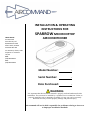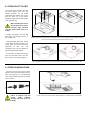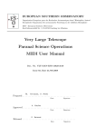
1
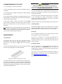
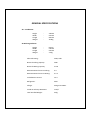
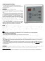
SPARROW OWNERS MANUAL
- INSTALLATION
- COMMISSIONING OF UNIT
- SPECIFICATIONS
- OPERATING INSTRUCTIONS
WARRANTY OF REFRIGERATED AIRCONDITIONING
Warranty within Australia
We undertake by this warranty to rectify, free of charge, at our nearest authorised service agent, any fault due to faulty workmanship or replacement of any faulty
components
within 12 months from the date of the first retail purchase thereof. This undertaking is conditional upon the appliance being installed and operated in accordance with
our instructions, and does not apply to consumable components such as filters, or to adjustments necessary due to misuse of airconditioner. Normal user maintenance,
setting of controls and transit damage are also excluded. No other person, firm or corporation is authorised by us to offer or give on our behalf any other or greater
warranty
than that given by us under this warranty. The benefits conferred by this warranty are in favour of the original retail purchaser and any other person deriving title to the
goods through or under such person and are intended to be separate from the additional to all other rights and remedies which they may have in law in respect of the
goods.
1.
2.
3.
In the event that warranty service is required, the purchaser must contact Aircommand Australia for service approval.
Contact information: phone +61 8 8445 2877, fax 08 8243 0628, or email [email protected]
Warranty repairs will only to be carried out by the manufacturer’s authorised service repairer.
It is the purchaser’s responsibility to deliver unit to the manufacturer’s nearest authorised Service Centre.
The manufacturer will not bear any costs involved in Service Agent’s travelling expenses or delivery charges.
Warranty outside Australia
1. Aircommand products are covered by 12 months warranty from date of first retail purchase.
2. For warranty enquiries outside Australia, please contact your national supplier .
* The warranty card must be completed and returned to the manufacturer for registration, or to the distributor in country of purchase. Online
warranty registration is available at www.aircommand.com.au/registration.html
GARANTIE FÜR KLIMAGERÄT MIT KÜHLFUNKTION
Garantie innerhalb Australiens
Wir verpflichten uns mit dieser Garantie, innerhalb von 12 Monaten ab Datum des ersten Einzelhandelskaufs, über unseren nächsten Vertragshändler jeden
durch fehlerhafte Verarbeitung entstandenen Defekt kostenlos zu beheben oder alle defekten Teile kostenlos auszutauschen. Diese Verpflichtung gilt unter
dem Vorbehalt, dass das Gerät im Einklang mit unseren Anleitungen installiert und betrieben wird, und gilt nicht für Verschleißteile wie z.B. Filter oder für
Korrekturarbeiten, die durch den Missbrauch des Klimageräts bedingt sind. Normale Wartung durch den Benutzer, die Einstellung der Bedienelemente und
Transportschäden sind ebenfalls ausgeschlossen. Wir haben keine anderen Personen, Firmen oder Unternehmen bevollmächtigt, in unserem Namen irgendeine
andere oder weiter reichende Garantie anzubieten oder zu geben als die von uns im Rahmen dieser Garantie erteilte. Die mittels dieser Garantie gewährten
Leistungen gelten zu Gunsten des ursprünglichen Einzelhandelskäufers oder jeder anderen Person, die ihren Anspruch auf die Waren durch oder von dieser Person
ableitet, und sind dazu gedacht, getrennt von allen zusätzlichen Rechten und Behelfen zu gelten, die ihnen kraft Gesetzes hinsichtlich dieser Waren zustehen..
1.
2.
3.
Für den Fall, dass eine Garantieleistung erforderlich wird, muss sich der Käufer mit Aircommand Australia zur Genehmigung der
Leistung in Verbindung setzen. Kontaktinfo: Tel. +61 8 8445 2877, Fax: 08 8243 0628 oder E-Mail: [email protected]
Unter die Garantie fallende Reparaturen werden nur durch den Vertragsreparaturdienst des Herstellers ausgeführt.
Die Lieferung des Geräts an das nächstliegende Service Centre des Herstellers ist Aufgabe des Käufers.
Der Hersteller deckt keine der durch die Anfahrtskosten des Vertragsdienstes oder Lieferkosten entstandenen Ausgaben.
Garantie außerhalb Australiens
1. Für die Produkte von Aircommand gilt eine 12-monatige Garantie ab Datum des ersten Einzelhandelskaufs.
2. Für Garantieanfragen außerhalb Australiens wenden Sie sich bitte an Ihren inländischen Händler.
* Die Garantiekarte ist auszufüllen und dem Hersteller, bzw. dem Vertriebshändler im Einkaufsland, zur Registrierung zuzuschicken. Die Garantie kann online unter der
folgenden Adresse registriert werden: www.aircommand.com.au/registration.html
GARANTIE DE CLIMATISATION RÉFRIGÉRÉE
Garantie pour l’Australie
Nous nous engageons par cette garantie à faire rectifier gratuitement par notre agent de service tout défaut résultant d’un défaut de fabrication ou de remplacer tout
composant défectueux dans les 12 mois suivant la date du premier achat de l’appareil au détail. Cet engagement est conditionnel à l’installation et à l’exploitation
de l’appareil conformément à nos instructions, et ne s’applique pas aux composants consommables tels que les filtres, ou à un réglage attribuable à la mauvaise
utilisation du climatiseur. L’entretien, les réglages des commandes et les dommages en transit sont également exclus. Aucune autre personne, firme ou entreprise n’est
autorisée par nous à offrir ou à donner en notre nom toute autre garantie ou une garantie supérieure à celle donnée par nous en vertu de cette garantie. Les avantages
conférés par cette garantie reviennent à l’acquéreur au détail original ou à toute autre personne qui deviendra propriétaire de l’appareil par le biais de cette personne
ou avec son autorisation et sont censés être supplémentaires à tous les autres droits et recours dont il pourra disposer légalement en ce qui concerne l’appareil.
1.
2.
3.
Au cas où un service de garantie serait nécessaire, l’acquéreur doit contacter Aircommand Australia pour obtenir une autorisation de service.
Cordonnées: téléphone +61 8 8445 2877, fax 08 8243 0628, ou email [email protected]
Les réparations sous garantie seront effectuées exclusivement par le réparateur autorisé du fabricant.
La responsabilité incombe à l’acquéreur de livrer l’appareil au Centre de service autorisé le plus proche du fabricant.
Le fabricant ne subira pas les frais de déplacement ou de livraison de l’agent de service.
Garantie en dehors de l’Australie
1. Les produits Aircommand sont couverts par une garantie de 12 mois à compter de la date du premier achat au détail.
2. Pour toute demande de renseignements en dehors de l’Australie, veuillez contacter votre fournisseur national.
* La carte de garantie doit être remplie et renvoyée au fabricant pour être enregistrée, ou au distributeur dans le pays de l’achat. Un enregistrement de garantie en ligne
est
disponible sur www.aircommand.com.au/registration.html
GARANTÍA DEL ACONDICIONADOR DE AIRE REFRIGERADO
Garantía en Australia
Nos comprometemos por medio de esta garantía a rectificar, sin cargo, en nuestra agencia de servicio autorizado, cualquier fallo causado por un componente
defectuoso dentro de los 12 meses contados a partir de la primera fecha de compra. Este compromiso es condicional a que el aparato haya sido instalado y
operado de acuerdo con nuestras instrucciones y no cubre componentes de consumo tales como filtros, o cualquier ajuste necesario debido al uso incorrecto del
acondicionador de aire. Se excluyen también las tareas de mantenimiento normales, el ajuste de los controles y cualquier daño ocurrido durante su transporte.
Ninguna otra persona, firma o corporación está autorizada a ofrecer o dar en nuestro nombre una garantía más extensa o diferente a la otorgada por esta garantía. Los
beneficios conferidos por esta garantía son a favor del comprador original y cualquier otra persona que tenga derecho al título de la mercadería a través o bajo dicha
persona y está separada de otros derechos adicionales o soluciones a las que puedan tener derecho, según la ley, respecto a las mercaderías.
1.
En el caso que se necesite hacer uso del servicio de garantía, el comprador debe ponerse en contacto con Aircommand Australia para la aprobación del
servicio. Información de contacto: Teléfono: +61 8 8445 2877, Fax 08 8243 0628 o Email [email protected]
2.
Las reparaciones cubiertas por la garantía deberán ser llevadas a cabo por el servicio de reparaciones autorizado por el fabricante.
3..
La entrega de la unidad al Centro de Servicio más cercano autorizado por el fabricante es responsabilidad del comprador
El fabricante no se hará responsable de ninguno de los costes involucrados por gastos de viaje o cargos de entrega por parte del agente
proveedor del
servicio
Garantía fuera de Australia
1. Los productos de Aircommand están cubiertos por 12 meses de garantía a partir de la primera fecha de compra.
2. Por cualquier información respecto a la garantía fuera de Australia, sírvase ponerse en contacto con su proveedor nacional.
* Esta tarjeta de garantía debe ser completada y enviada al fabricante para su debida registración o alternativamente al distribuidor en el país de compra. La
registración de la garantía puede hacerse también online en: www.aircommand.com.au/registration.html
HEAD OFFICE
Aircommand
Australia Pty Ltd
954-956 Port Road
Albert Park, SA 5014
ACN 007 592 239
INSTALLATION & OPERATING
INSTRUCTIONS FOR
SPARROW MKII ROOFTOP
AIRCONDITIONER
For warranty claims, sales
enquires or customer
service
Call:
(08) 8345 8444
Fax:
(08) 8243 0628
Model Number:
.
Serial Number:
.
Date Purchased:
.
WARNING
It is important that this installation manual is properly read and understood before
installation. The unit must be installed by a qualified service technician. Failure to
properly install the unit or attempting to modify it in any way can be extremely
hazardous and may result in property damage and personal injury.
Aircommand will not be held responsible for problems relating to incorrect
or improper installation methods.
GENERAL SPARROW UNIT INFORMATION
I. PURPOSE
The Aircommand SPARROW air conditioning unit is designed for installation on the roof of a caravan or recreation vehicle to
provide reverse cycle heating and cooling
-The roof must be capable of supporting the weight of the unit (33kg)
-The absolute minimum thickness of the roof must not be less than 25mm
-The maximum thickness of the roof must not exceed 125mm
-Trimming of the ductwork may be necessary depending on the roof thickness
It is important that the unit is installed properly and according to the recommended guidelines.
Aircommand will not be held responsible for problems relating to incorrect or improper installation methods.
II. ENSURING EFFECTIVE OPERATION
The effectiveness of the air conditioner is dependent on several factors e.g. size and heatload of the van. When an Aircommand
unit is installed in a van or motorhome Aircommand assumes that the vehicle is well insulated (25mm of foam minimum) in all
walls and roof, that the windows are of moderate size (preferably double glazed) and the roof hatches are moderate, insulated
and airtight when closed. Other methods of reducing heatload include:
-Closing all doors, hatches, windows and blinds
-Position the vehicle so if an annex is used, it will face the sun and protect the windows from direct radiation
-Turning off appliances that might increase the heatload
-Ensuring the caravan/RV is parked in a shaded position
In periods of extreme high temperature it is recommended to start the air conditioner earlier in the morning to greatly improve
its ability to cope with the expected high heat load.
III. CONDENSATION
In areas of high humidity, the humid air within the van will cause “sweating” or condensation in parts of the unit as the humid
warm air contacts the colder air discharge system. If this occurs please ensure the following:
-Closing all doors, hatches, windows and blinds to limit the ingress of warm humid air
During operation the air conditioner will remove large quantities of water from the inside air and if warm humid outside air is
limited, then so the condensation will reduce greatly. Avoid running the inside fan on LO or AUTO in such conditions. Running
the fan on HI fan speed will result in higher airflow and reduce the tendency to have condensation form.
Aircommand will not be held responsible for damage caused by condensation
IV. GENERATORS
The SPARROW can be started using a generator. Any generator used should have a steady sine wave at 50hz, and be able to
handle the compressor start up demand. However given the vast range in quantity and quality of generators on the market,
Aircommand cannot recommend a specific model or brand.
Aircommand will not be held responsible for damages due to the use of improper generators and such use may void your
warranty
INSTALLATION PARTS LIST
MAIN COMPONENTS
1) SPARROW MkIII
Rooftop Airconditioner
1
2) Roof Seal Gasket
3) Black Plastic Duct
4) Brace Assembly
2
5) Plenum Filters x2
6) Plenum Cover
3
4
5
6
FITTINGS & FIXTURES
7) M8 Bolts x 4
5
8) Hold Down Bars x 4
9) Plenum Cover Screws x 4
10) Self Tapping Screws x 6
7
8
9
10
BEFORE INSTALLATION
Ensure that the installation instructions have been properly read and understood
Installation must confirm to nation wiring regulations and in particular AS3001 – 2008
DO NOT attempt to modify or add components to the installation procedure
This equipment must only be serviced by a licensed refrigeration mechanic
If your installation varies from the method outlined please contact Aircommand for specialty advice
WARNING
Failure to properly install the unit or attempting to modify it in any way can be extremely hazardous and may result in property
damage and/or personal injury
Aircommand will not be held responsible for issues arising from incorrect or improper installation methods
1. INSTALLATION POSITION
DIRECTION OF TRAVEL
REAR OF UNIT
Minimum 100mm clearance from
rear grills to any vertical face
Minimum 50mm clearance to any
45 degree face
Fig 1: SPARROW Vent clearances
Before beginning, mark out the position of the unit
considering the following important requirements:
DIRECTION OF TRAVEL
- The air conditioner should be situated as
centrally as possible on the van, to ensure even air
distribution.
- If the caravan is over 16’ in length, or has an
unusually high heatload, Aircommand would
suggest a larger capacity unit.
- When considering the installation position,
remember to check for clearance around the
plenum inside the van.
- Avoid an installation position where a bulkhead,
cupboard or light fitting could interfere with the
discharge air flow from the plenum.
It is important that the unit is never
more than 5° from the horizontal and the
rear of the unit should never be higher
than the front
- Contact Aircommand if your installation differs
significantly
90
120
520
- The front of the unit MUST face the direction of
travel, failure to follow this instruction will result
in damage to the condenser fans.
90
DIRECTION OF TRAVEL
14” x 14”
(356mm)
SQUARE
HOLE
Fig 2: The foot print of the rooftop unit, and the plenum, measured from the hole
- The above outline on the left shows the minimum clearance required around the
SPARROW unit on the roof of the vehicle, distances shown are calculated from a
14” square hole (356 x 356mm)
- The above outline on the right shows the minimum clearance required around
the Plenum located on the ceiling inside the vehicle, distances shown are
calculated from a 14” square hole (356 x 356mm)
2. ASSESS ROOF STRENGTH
- The roof members MUST be strong enough
to support the weight of the unit (up to 33kg)
without any roof deflection that will cause
“pooling” of water around the unit. If the
roof is weak or the unit is to be installed on a
pop top caravan the use of an external “H”
frame is required.
DIRECTION OF TRAVEL
LONGITUDINALS MUST BE
FIXED SECURELY TO
TRANSVERSE ROOF MEMBERS
- If the roof does not have an existing hole
one must be cut. Cut from the roof then use
the roof hole as a guide to cut through the
ceiling. Contact your caravan manufacturer
for the best method to cut through the roof.
- The square hole in the roof (356 x 356mm,
14” x 14”) MUST be boxed up with minimum
20mm square timber to provide a structure
strong enough to withstand the compression
of the installation bolts. This is also to ensure
that air in not drawn from the roof cavity
(Fig 3 & 4). Remember to leave access for
wiring.
Fig 3: Shows an ideal roof structure with strong longitudinals and a 14’ hole boxed
20mm MIN
BE SURE TO ALLOW SPACE
FOR POWER CABLE
- Longitudinals MUST be fixed securely to the
transverse roof members to transfer load
(see Fig 3).
WARNING
There may be electrical wiring located
between the roof and ceiling. Ensure that
power is properly disconnected at the
supply (mains and/or battery). Failure to do
so may result in personal injury or death
TIP: Always use crawl boards across the roof
to avoid damage
THE ROOF CAVITY MUST
BE FRAMED TO SUPPORT
THE UNITS WEIGHT
Fig 4: The roof cavity MUST be boxed with timber to provide a solid structure
3. INSTALLING ROOF GASKET
- Ensure that the roof is clean, dry and free
from grease or oil.
- Remove the paper backing from gasket and
position over square hole.
- Gasket must be applied with self adhesive
side down. Note orientation of gasket to
direction of travel (Fig 5). Press gasket down
to ensure good adhesion.
- Run a bead of silicone between the roof and
the gasket, around the entire gasket
perimeter, to ensure water cannot leak
between the gasket and the roof surface. DO
NOT apply silicone between the gasket and
the air conditioner itself.
FRONT OF VEHICLE
Fig 5: Shows the placement of the roof gasket over the hole. Note the positioning in
relation to the front of the vehicle
4. POSITION SPARROW ON ROOF
- Remove the air conditioner from the
carton.
- Position the unit over the gasket so that
the corners of the square hole in the
caravan roof line up with the corners of
the square hole underneath the unit
(Fig 6).
TIP: Have one person inside the vehicle
looking through the hole while the other
is on the roof adjusting the position of the
unit
The unit weights approximately
33kg. Ensure a two person lift or
use a mechanical hoist to avoid
the risk of injury.
Fig 6: Position the SPARROW over the roof gasket and set it down gently
- DO NOT slide the unit on the roof, this
may damage the gasket and result in
leaks
- Four M8 mounting holes on the chassis
underneath the air conditioner will line
up with the corners of the square roof
hole (Fig 7).
Fig 7: Shows the view from under the roof
Position the SPARROW so the 4 mounting holes (circled) line up with the corners
5. CONNECT ELECTRICAL SUPPLY
- This unit MUST be installed in
accordance with State and National
Wiring regulations and in particular
AS3001 – 2008
- Refer to wiring diagram (Fig 9). Refer Fig
8 for position of terminal block
Fig 8: Highlights the position of the terminal strip underneath the unit
- Connect electrical supply to terminal
block. Note position of active, neutral and
ground wires (Fig 9)
WARNING
Ensure that power is properly
disconnected at the supply (mains
and/or battery). Failure to do so may
result in damage to the unit and personal
injury or death.
- When connecting wires into terminal
strip apply suitable clamping pressure to
ensure wire is secure while taking care
not to over tighten and damage the
exposed wire ends.
Fig 9: Shows the positioning of the electrical wires into the terminal strip
6. ASSESS ROOF THICKNESS
Roof thickness (mm)
- Measure the roof thickness and consult the
table across to check if adjustments to the duct
length are required.
- NOTE if the duct length needs to be adjusted
then cut the excess from the un-notched end.
(See section 7 for picture of duct notch)
Failure to properly alter the duct
length can result in imporoper airflow
and severly limit the ability of the
airconditioner to cool or heat
Duct length required (mm)
Include ‘H’ frame if used
125
150 (as supplied)
100
125 (cut 25)
80
105 (cut 45)
60
85 (cut 65)
40
65 (cut 85)
25 (absolute minimum)
50 (cut 100)
7. ASSEMBLE DUCT
- Thread a hold down bar onto
the M8 bolt and push the bolt
almost all the way into the hole
in each corner of the brace
(Fig 10)
- Leave a 10mm gap between the
hold down bar and the recess in
the plastic brace. This will allow
for easier engagement with the
four corresponding threaded
holes in the unit.
- Turn the assembly over and add
the black plastic duct work to the
top of the assembly with the
notch upwards (Fig 11). The
notch is shown circled below.
Fig 10: Insert the four M8 bolts and hold down bars into the corners of the brace
- Align the notch with the inside
fans power cable.
When attaching the
duct to the unit take
care to ensure it forms
a tight, unbroken seal that
doesn’t allow cold air to escape.
Fig 11: Fit the black plastic duct onto the brace assembly ensuring a tight, sealed fit
8. ATTACH DUCT TO UNIT
- Raise the brace assembly and slip
the black plastic duct over the
outside diameter of the outlet
underneath the rooftop unit. Ensure
that the notch cut in the plastic
ductwork aligns with the fans power
cable (Fig 12 & 13).
When attaching the duct to
the unit take care to ensure
it forms a tight, unbroken
seal that doesn’t allow cold air to
escape.
- Engage and tighten the four M8
bolts with the threaded inserts in
the rooftop unit.
Fig 12: Raise the duct assembly up to the roof hole, ensuring the black plastic duct work forms a
tight fit around the evaporator fan underneath the unit. Then engage the four M8 bolts, taking
care to ensure the hold down bars slot into their recesses
- Recommended tightening torque
of the bolts is 10.8 N.m (8 lb-ft). As a
rough guide the bolts should be
tightened so that the unit
compresses the roof seal gasket to
approximately half its height.
- As the bolts are tightened ensure
that the hold down bars slot into
their recesses in the brace (Fig 12).
Fig 13: Highlights how the notch on the plastic duct slots over the wire from the evap. Fan
9. ATTACH PLENUM COVER
- Connect the key pad control cables
together (see Fig 14 and below). Be sure
that the plug joins the corresponding
wire colours together (yellow to yellow,
red to red etc.)
Failure to properly plug the
control
cables
together
correctly will result in loss of
power to display
Fig 14: Connect the control panel cables together to provide power to the display
9. ATTACH PLENUM COVER
- Secure the main plenum cover to the
duct assembly with the 4 screws
provided (Fig 15).
TIP: It is important that these screws
are not over tightened otherwise the
plenum may crack.
- Remove the filter elements by pulling
them out of the plenum, and use the six
self tapping counter sunk screws to
secure the covers edges to the caravan
ceiling (Fig 16). In some instances a very
small pilot hole may need to be drilled
to guide the screws into place.
- Replace the filters by sliding them into
the plenum until they click into place
-Your installation is now complete.
Fig 15: Secure the main plenum cover to the duct assembly with the four
screws provided
Fig 16: Remove the plenum filters and use the six self tapping screws to
secure the plenum over to the ceiling of the caravan. Be sure not to over tighten.
INSTALLATION IS NOW COMPLETE
COMMISSIONING OF THE UNIT
1. Turn the power on at the circuit breaker
2. Press the ON/OFF button and press the MODE button to
select FAN
3. Cycle through the LO, MED and HIGH fan speeds checking
that all speeds run.
4. Set mode to COOL, adjust temp via up/down buttons to say
4oC less than the display temp (I.e. Room temp) compressor
will start within three minutes.
5. Set mode to HEAT, similarly set temp to say 4oC above
display temp. Compressor will start within three minutes.
After a few minutes the fan will start and warm air will be
apparent.
N.B. Regardless of the mode selected there will always be at
least a 3 minute delay before the compressor starts. If the unit
is turned off it is important that the compressor be given at
least 3 minutes before being re-activated
MAINTENANCE
I. Plenum Filters
The plenum filters are the only parts that require routine
maintenance. They must be cleaned periodically to ensure
that they do not become clogged with dust and other
particles.
To clean the two plenum filters, first remove them both from
the plenum by pulling them out of the assembly.
WARNING
Airborne particles can pose a health risk, particulalry to
young children and the elderly. Ensure that filters are cleaned
in a safe and well ventilated area
If a more thorough clean is required then the filters can be
washed out using warm soapy water. Care must be taken to
avoid ripping the fabric.
The filters should be cleaned every two weeks or more when
in use. Prolonged use, higher concentrations of airborne
particles and various other factors may result in the filters
needing to be cleaned more often.
Replacement filters can be ordered directly from Aircommand.
II. Mounting Bolts
Aircommand suggests that the hold down bolts are initially
checked for tightness within the first 3 months of installation,
and thereafter every 12 months if the van is in constant use.
III. Storage
The air conditioner should be run on a routine basis to ensure
the components remain in working order.
If the van is in storage or is to remain unoccupied for an
extended length of time it is recommended than the air
conditioner is allowed to run uninterrupted for 20-30min once
every six months.
IV. Warranty Claims
The unit comes with a one year manufactures warranty from
date of purchase. It is IMPORTANT that you read and
understand the conditions of the warranty agreement which
are included with the unit.
If you have a claim please contact Aircommand directly on
(08) 8345 8444 alternatively you can fax (08) 8243 0628 or
email [email protected]
Please have your unit serial number ready
Fig 18 shows the plenum filter when removed
The state of the filters can be ascertained from its appearance,
the filters are translucent, and if they appear clogged then
they should be cleaned. Generally the filters can be cleaned
sufficiently by tapping them together to shake loose the dust
and particles trapped inside.
GENERAL SPECIFICATIONS
Air – Conditioner
Height
Width
Length
Weight
-
240mm
552mm
905mm
30.6kg
-
65mm
535mm
555mm
2.4kg
Air Discharge Plenum
Height
Width
Length
Weight
Electrical Rating:
240V, 50hz
Nominal Cooling Capacity:
2KW
Nominal Heating Capacity:
2 KW
Maximum Rated Current Cooling:
4A
Maximum Rated Current Heating:
4.2 A
Locked Rotor Current:
15 A
Refrigerant:
407C
Charge:
540 grams R407C
Inside Air Delivery Maximum:
110 l/s
Total Installed Weight:
33kg
OPERATING INSTRUCTIONS
- Turn the unit on by pressing the ON/OFF button once.
- Press the MODE button to cycle through options Cool,
Dry, Heat and Fan.
COOLING
- Cycle mode button to highlight COOL.
- You may select High, Med, Low or Auto fan speeds by
pressing the fan button. It is recommenced that you choose
Auto.
- Now select the desired room temperature (herein referred
to as SETPOINT) by pressing the TEMP up or down keys,
the readout will flash the set point temperature. Keep
pressing the button until it flashes your desired set point. In
approx. 5 seconds the display will resume reading the actual
room temperature. The compressor will have a delayed start
usually 3 minutes before unit starts to cool.
N.B: Any interruption to the power supply will cause the unit
to delay compressor start up.
- For simply recirculating air, choose the FAN mode.
Choose any of the three fan speeds by pressing FAN button.
N.B: Temperature button is invalid in Fan only mode.
HEAT
- To heat, press MODE button to highlight HEAT.
- Select desired set point temperature by pressing TEMP buttons up or down. It is recommended that AUTO fan speed
by selected.
- After the delay, the compressor will start. Usually the fan will stop and will not re-energize until the heat exchanger
has warmed and then the fan will start to blow warm air.
DRY
- The DRY mode is used when the room temperature is close to comfortable but you wish to dehumidify.
- Press MODE button to highlight DRY.
- Set the temperature to desired set point. N.B: the fan speed is locked in LOW.
- The compressor will cycle on and off at approximate intervals of 6 minutes to extract moisture from the air.
SLEEP
- With the unit operating in cool mode, press sleep button to highlight the sleep light. The unit over the next hour will
automatically raise the set point by 1c. Conversely in heat mode, the set point will be lowered 1c.
- The TIMER may be used to turn off the unit in the future (up to 24 hours) OR may be used to turn on the unit up to
24 hours in the future.
- Press TIMER button once and the display will flash. Within 3 seconds, press the timer button until you have set
desired time into the future to turn unit off. A subsequent press of the timer button will allow the time to start the unit
to be programmed.
LOCKING
- This provides a means of locking in the mode and fan settings. To lock, press temp down key simultaneously with
MODE button. Hold for 3 seconds and the lock indicator will light. To unlock, repeat above procedure.
DISPLAY SETTING
- To change readout from Celsius to Fahrenheit or vice versa: Press temp down key simultaneously with the Fan key.