1
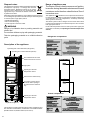
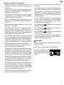
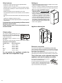
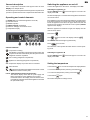
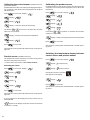
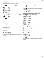
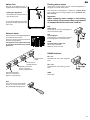
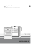
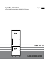
Operating instructions Combined refrigerator-freezer with explosion-proof interior container Read the operating instructions before switching on for the first time Page 16 EN 7083 151-00 LCexv Disposal notes Range of appliance use When disposing of the appliance, ensure that the refrigerant circuit is not damaged to prevent uncontrolled escape of the refrigerant it contains (data on type plate) and oil. The appliance is not suitable for use in explosion-hazard areas. The appliance contains reusable materials and should be disposed of properly - not simply with unsorted household refuse. Appliances which are no longer needed must be disposed of in a professional and appropriate way, in accordance with the current local regulations and laws. • Disable the appliance. • Pull out the mains plug. • Cut through the connection cable. WARNING Danger of suffocation due to packing material and plastic film! The interior, which is free from sources of ignition, is used for storing flammable substances in closed containers and is therefore classified as a Zone 2 hazardous area. For the storage of valuable or temperature-sensitive substances or products the use of an independent, constantly monitoring alarm system is necessary. This alarm system must be designed so that each alarm status is detected immediately by an authorised person who can then take appropriate action. Position the temperature sensor for this system in the upper part of the interior container (see Opening for external temperature sensor). Do not allow children to play with packaging material. Take the packaging material to an official collection point. Refrigerator compartment Description of the appliance Operating and control elements (refrigerator) Operating and control elements (freezer) The ventilation slots on the inside must not be covered. Type plate Opening for external temperature sensor Defrost water collection tray A container can be placed under the drain opening in the defrost water collection tray. Opening for external temperature sensor Adjustable-height feet The appliance complies with the relevant safety regulations and EC Directives 2004/108/EC, 2006/95/EC and ATEX 94/9/EC (EN/IEC 60079-15, EN/IEC 60079-0, EN 1127-1). 16 Freezer compartment Safety instructions and warnings •To prevent injury or damage to the unit, the appliance should be unpacked and set up by two people. •In the event that the appliance is damaged on delivery, contact the supplier immediately before connecting to the mains. •To guarantee safe operation, ensure that the appliance is set up and connected as described in these operating instructions. •Disconnect the appliance from the mains if any fault occurs. Pull out the plug, switch off or remove the fuse. •When disconnecting the appliance, pull on the plug, not on the cable. •Any repairs and work on the appliance should only be carried out by the customer service department, as unauthorised work could prove highly dangerous for the user. The same applies to changing the mains power cable. •Do not allow naked flames or ignition sources to enter the appliance. When transporting and cleaning the appliance, ensure that the refrigerant circuit is not damaged. In the event of damage, make sure that there are no ignition sources nearby and keep the room well ventilated. •Do not stand on the plinth, drawers or doors or use them to support anything else. •This appliance can be used by children of 8 years old and over, and also by persons with restricted physical, sensory or mental capacity or lack of experience and knowledge, if they are supervised or have been instructed on safe use of the appliance and understand the resulting risks. Children must not be allowed to play with the appliance. Cleaning and user maintenance must not be carried out by children without supervision. EN •Do not use electrical appliances inside the appliance. •If you have a lockable appliance, do not keep the key near the appliance or within reach of children. •The appliance is designed for use in enclosed areas. Do not operate the appliance outdoors or in areas where it is exposed to splash water or damp conditions. •Do not install the appliance in the immediate vicinity of an air-conditioning unit. The appliance should also not be operated under a wallmounted air-conditioning unit. •The appliance is not suitable for storing drugs pursuant to DIN 58345. •The appliance is not suitable for storing blood bottles pursuant to DIN 58371. •The appliance is not suitable for storing blood plasma pursuant to DIN 58375. •In special fields of application which are subject to their own standard, the user is responsible for complying with this standard. WARNING Danger of sparks produced by friction due to dust on the fan blades. Do not store dusty objects in the appliance. Clean the ventilation slots on the re-circulated air fan every month using a vacuum cleaner. •Avoid prolonged skin contact with cold surfaces or chilled/frozen food. This could cause pain, numbness and frostbite. In the case of prolonged skin contact, protective measures should be taken, e.g. gloves should be worn. •Do not consume food which has been stored for too long, as it could cause food poisoning. 17 Other features - Audible and visual temperature alarm (adjustable limits). - Audible and visual door open alarm. - Floating contact for connection to a remote monitoring system. - Serial interface (RS485) for external temperature and alarm documentation. - Maximum/minimum interior temperatures are stored. - Last 3 temperature alarms are saved with time, date and duration of alarm. - Last 3 power cuts are saved with time, date and duration of power cut. - Opening for installing a reference sensor. - Safety thermostat to avoid temperatures below +2°C (refrigerator compartment). It is essential to use these safety facilities to avoid damage to stored items. These facilities must not be deactivated or decommissioned! Setting up • Avoid positioning the appliance in direct sunlight or near cookers, radiators and similar sources of heat. • The floor on which the appliance stands should be horizontal and level. Compensate for uneven floors with the adjustable feet. • Do not cover ventilation open- ings or grille. • Standard EN 378 specifies that the room in which you install your appliance must have a volume of 1 m3 per 8 g of R 600a refrigerant used in the appliance, so as to avoid the formation of inflammable gas/air mixtures in the room where the appliance is located in the event of a leak in the refrigerant circuit. The quantity of refrigerant used in your appliance is indicated on the type plate on the inside of the appliance. Appliance dimensions Climate rating The climate rating indicates the room temperature at which the appliance may be operated in order to achieve full refrigeration performance. The climate rating is indicated on the type plate. The position of the type plate is shown in the section entitled Description of the appliance. Climate rating SN N ST T SN-ST SN-T Room temperature +10°C to +32°C +16°C to +32°C +16°C to +38°C +16°C to +43°C +10°C to +38°C +10°C to +43°C Do not operate the appliance outside the specified room temperature range. Electrical connection Only operate the appliance with alternating current (AC). The permissible voltage and frequency are indicated on the type plate. The position of the type plate is shown in the section entitled Description of the appliance. The socket must be properly earthed and protected by a fuse. The tripping current of the fuse must be between 10 A and 16 A. The socket must not be situated behind the appliance and must be easily accessible. Do not connect the appliance using an extension cable or extension socket. Do not use stand-alone inverters (conversion of direct current to alternating/three-phase current) or energy-saving plugs. Risk of damage to the electronic control system! 18 General description Time or temperature information that appears after the word Display = are sample values. The following sections explain how the refrigerator compartment is operated. Operation of the freezer compartment is identical to this. Operating and control elements 1ON/OFF button (to switch the appliance on and off) 2Selection buttons 3Set button (Enter) 4Audible warning on/off button 5Button for calling up stored alarm events 6Temperature display EN Switching the appliance on and off Connect the appliance to the mains - the display reads OFF. Switching the appliance on Keep the ON/OFF button display reads ON. pressed for approx. 5 seconds - the No alarm is displayed or sounded when the appliance is switched on for the first time. If the appliance is disconnected from the mains for a long time after it has been switched on for the first time and if the temperature inside the appliance rises above the upper alarm limit, this will be detected as a fault by the electronic control system (HACCP appears in the display). When the appliance is switched on again, this display must be reset as shown below. Press button . Press for 5 seconds. The display will read + . The HACCP LED will now light up permanently. Press Control elements Compressor is running LED flashing - refrigeration unit switches on after a delay.The compressor will start automatically after the pressure in the refrigerant circuit has equalised. Fan is running (refrigerator compartment) for 5 seconds. The electronic control system will switch back to normal operating mode. Switching the appliance off Keep the ON/OFF button display reads OFF. pressed for approx. 5 seconds - the Appliance is defrosting (refrigerator compartment) AUX Temperature display via product sensor is activated Alarm function If appears in the display, the appliance has a fault. Consult your nearest customer service point. HACCP (Hazard Analysis Critical Control Point) The HACCP display means that the power supply and interior temperature of the appliance are recorded. If HACCP flashes in the display, there has either been a power failure or the temperature in the appliance exceeded the permissible range. Setting the temperature • Press button for 1 second. The temperature display flashes. • To increase the temperature (warmer): press button • To reduce the temperature (colder): press button • Press button . . again. The desired temperature setting is saved. 19 Audible warning signal The audible warning signal will sound in certain alarm events. It . can be cancelled by pressing button Deactivating the audible warning signal function The audible warning signal function can be completely deactivated if necessary. Note Door open alarm When the door is opened, the LED play begin to flash. and the temperature dis- In this case, the sentence stated in these operating instructions "The audible warning signal sounds" must be skipped when reading the section in question. Press When the door has been left open for more than 60 seconds, the LED begins to flash, and and the temperature indication flash alternately in the display. for 5 seconds. Display = Display = The audible warning signal sounds (unless the audible warning signal function has been deactivated). Display = If the door has to stay open for longer in order to insert items to be cooled, cancel the audible warning signal by pressing button . Display = Use buttons Setting the delay time for the door open alarm The time before the audible warning signal sounds after the door has been opened can be adjusted. Press = audible warning signal function deactivated Display = Display = Press Display = The electronic control system will switch back to normal operating mode. Display = Display = Display = (minute) Setting range = 1 - 5 minutes Use buttons and to select the desired setting. Display = for 5 seconds. The electronic control system will switch back to normal operating mode. 20 to select the desired setting. = audible warning signal function activated for 5 seconds. Display = Display = Press and for 5 seconds. Audible warning signal settings The audible warning signal will be muted for the current alarm after the button has been pressed. Complete the following steps if you want the audible warning signal to reactivate automatically. Press for 5 seconds. Display = Alarm messages 1.LED flashes appears in the display, the appliance has a fault. Consult If your nearest customer service point. 2.LED flashes, the display reads HI or LO The interior is too warm (HI) or too cold (LO). Display = The audible warning signal sounds (unless the audible warning signal function has been deactivated). Display = Display = Note The alarm parameters can be adjusted. See Adjusting the alarm parameters. Display = 3. HA/HF/HACCP flashes Display = There has been a power cut (HF) of some length or the interior was too warm or too cold (HA) during a certain period of time. Up to three alarm events can be stored and called up. Display = Display = Alarm test This test checks the function of the internal and any external connected alarm device. Display = Automatic reactivation of the audible warning signal is now active. The time before the audible warning signal sounds again must be set. Display = The appliance does not stop its refrigerating function during this test. Activating the test Press + for 5 seconds. Display = Time in minutes after which the audible • The display will change to a temperature value of 0.2°C below the set upper alarm limit. has been pressed. Setting • The temperature value will now rise by 0.1°C every 2 seconds. warning signal will sound again after the button range = 1 - 120 minutes. Use buttons and to select the desired setting. Display = Press EN for 5 seconds. The electronic control system will switch back to normal operating mode. • When the upper alarm limit is reached, will appear in the display. An external alarm unit connected to the floating alarm output will now be activated. • The temperature value will continue to rise up to 0.2°C above the upper alarm limit. • The same process will take place automatically for the lower alarm limit. The LED will appear in the display. will be lit during the test. The electronic control system will automatically switch back to normal operating mode. Cancelling the test prematurely Press for 5 seconds. Note If the values of the upper and lower alarm limit (AL and AH in the section entitled "Adjusting the alarm parameters") are set to 0, and will appear in the display during this test. 21 Adjusting the alarm parameters The alarm limits (difference to the set temperature) and the alarm delay (delay until alarm goes on) can be adjusted. Press Calling up stored alarm events and reading the temperature progression Display = for 5 seconds. Display = Scroll through the list using Display = . Number of temperature alarms Display = Last temperature alarm Display = Last temperature alarm but one Temperature alarm before Display = Display = Display = or Number of power cuts Last power cut Last power cut but one Lower alarm limit Power cut before Display = temperature difference in °C Use buttons and to select the desired setting. Important note Set positive values only. Upper alarm limit Display = temperature difference in °C Use buttons and to select the desired setting. Important note Set positive values only. Display = Display = and button. Press this button Note: You can exit the menu at any time by pressing 5 seconds. for If no button is pressed within 60 seconds, the electronic control system switches back automatically. Resetting the recorded temperature progression Complete the following steps if you wish to reset the value saved for in the previous section to 0. Press the button Display = to select the desired setting. for 5 seconds. The electronic control system will automatically switch back to normal operating mode. 22 Lowest measured temperature Select the required item using the Display = Press Maximum (highest) measured temperature Display = Display = alarm delay in minutes Use buttons Period in hours in which the maximum and minimum interior temperatures were measured again to return to the list. Display = Display = Press or until appears in the display. - for 5 seconds. Display = . The values for and (highest and lowest measured interior temperature) are then reset to the current interior temperature. Press for 5 seconds. The electronic control system will switch back to normal operating mode. Example of an alarm query Setting the real time clock The real time clock is preset (CET). Other time zones or summer/ winter time must be adjusted manually. Situation: HA/HF/HACCP flashes in the display. Press Display = Display = There has not been an alarm status with a too high or too low temperature. You . must switch to display Display = Press this button until Display = Display = appears in the display. 1 power failure has occurred. Press Display = Display = Display = Month 05 (May) Display = Day 30 = save new setting Display = Hour 23 Display = Display = Minute 14 Display = The power failure lasted 3 hours. Month (1-12) = save new setting Display = for 5 seconds. The display will read buttons. Set the month by pressing the buttons. Year 2014 + Year 2014 Set the year by pressing the Display = Display = Day (1-31) Display = Display = Set the day by pressing the buttons. Days of the week (1 = Monday, 7 = Sunday) Set the day of the week by pressing the buttons. = save new setting . Display = The HACCP LED will now light up permanently. HA/HF is cancelled in the display. Display = The electronic control system is now ready for the next alarm. Press = save new setting Last power failure. for 5 seconds. Display = Display = Display = Display = EN Hour (0-23) Set the hour by pressing the buttons. = save new setting for 5 seconds. The electronic control system will automatically switch back to normal operating mode. Display = Display = Minute (0-59) Set the minutes by pressing the buttons. = save new setting Press for 5 seconds. The electronic control system will switch back to normal operating mode. Note When be reset. appears in the display, the real time clock must 23 Calibrating the control sensor (standard sensor for temperature control) Possible tolerances of the control sensor (the displayed temperature compared to the actual interior temperature) can be offset with this function. for 5 seconds. Display = Press Calibrating the product sensor Possible tolerances of the product sensor (the set temperature compared to the actual interior temperature) can be offset with this function. Display = Display = Display = Display = Display = Display = correction value set at the factory Use buttons or to increase or decrease the correction value in 0.1°C increments. Display = actual (corrected) interior temperature Display = Press for 5 seconds. The electronic control system will switch back to normal operating mode. Product sensor (available accessory) The temperature may be measured or recorded at any point in the interior using the product sensor. Display = Use buttons Press Switching the temperature display between control sensor and product sensor Press Press for 5 seconds. The electronic control system will switch back to normal operating mode. If appears in the display, the product sensor has not been activated. If appears in the display, the product sensor has not been connected, or is faulty. 24 for 5 seconds. Display = Display = Display = (control sensor) (product sensor) If the product sensor is activated, AUX appears in the display. Display = Display = Display = for 5 seconds. The electronic control system will switch back to normal operating mode. for 5 seconds. Display = Display = to increase or decrease the correction Display = actual (corrected) product sensor temperature Activating the sensor Display = or . value in 0.1°C increments. • Connect sensor (see section entitled External alarm). Press for 5 seconds. Display = Press Press for 5 seconds. The electronic control system will switch back to normal operating mode. EN Changing the network address When connecting several appliances via the RS485 interface, each appliance must have its own network address. for 5 seconds. Display = Press Display = • Symbol + alternating display of • Symbol + temperature before the start of the defrost phase • Symbol + Display = to change the network address ( - ). . Changing the display during the defrost phase Press Display = Press for 5 seconds. Display = Display = for 5 seconds. Display = The electronic control system will switch back to normal operating mode. Display = Resetting the parameters to factory settings Display = The alarm limits and sensor calibration values can be reset to the factory settings using this function. Pull out the mains plug. Keep and the current tem- (factory setting). Display = or The following indications can be set for the defrost phase. perature in the interior of the appliance. Display = Use buttons Setting the display indication for the defrost phase (refrigerator) pressed and connect the mains plug. Display = Display = Display = Use buttons and to select the desired setting. = alternating display of the interior of the appliance. and the current temperature in = temperature before the start of the defrost phase. = display of The electronic control system will switch back to normal operating mode. only. Display = Press for 5 seconds. The electronic control system will switch back to normal operating mode. 25 Defrosting Refrigerator compartment The refrigerator compartment defrosts automatically. 1The defrost water drains into a tray situated below the evaporator. This tray must be emptied from time to time. Pull the tray out towards you and empty. 2To avoid having to empty the defrost water collection tray frequently, you can place a container under the drain opening in the tray. Freezer compartment After the appliance has been in operation for some time, a layer of frost or ice will form on the inside walls. This increases energy consumption. You should therefore defrost the appliance regularly. • To defrost, switch the appliance off. • Remove the drawers. • Transfer items to other appliances. • Leave the door of the appliance open while defrosting. After defrosting mop up the remaining water with a cloth and clean the appliance. Do not use any mechanical devices or other artificial aids for defrosting other than those recommended by the manufacturer. Cleaning Before cleaning always switch off the appliance. Pull out the mains plug or switch off or unscrew the fuse. • Clean the inside, equipment and outer walls with lukewarm water and a little detergent. Do not use abrasive or acid cleaners or chemical solvents. Do not use steam cleaners because of the risk of injury and damage. • Ensure that no cleaning water penetrates into the electrical components or ventilation grille. • The dust should be removed from the refrigeration unit and heat exchanger - metal grid at the back of the appliance - once a year. • Do not damage or remove the type plate on the inside of the appliance. It is very important for servicing purposes. Warning! Only clean plastic parts with a damp cloth! Risk of electrostatic discharge. 26 Malfunctions If a malfunction occurs during operation, check whether it is due to an operating error. You may be able to rectify the following faults yourself: • Appliance does not function: –Is the appliance switched on? –Is the plug correctly fitted in the mains socket? –Is the fuse intact? • Loud running noise: –Is the appliance set up firmly on the floor? –Does the appliance cause nearby items of furniture or objects to vibrate? Please note that noises caused by the refrigerant circuit cannot be avoided. • The temperature is not low enough: –Is the temperature setting correct (see "Setting the temperature")? – Does the separately installed thermometer show the correct reading? – Is the ventilation system working properly? – Is the appliance set up too close to a heat source? • appears in the display: –Reset the real time clock (see "Setting the real time clock"). If none of the above causes apply and you cannot rectify the fault yourself, contact the nearest customer service department stating the type designation 1, service number 2and appliance number 3 as indicated on the type plate. The position of the type plate is shown in the section entitled Description of the appliance. Shutting your appliance down If your appliance is to be shut down for any length of time, switch it off and disconnect the plug or switch off or unscrew the fuse. Clean the appliance and leave the door open in order to prevent unpleasant smells. Safety lock Floating alarm output EN The lock in the appliance door is equipped with a safety mechanism. These three contacts can be used to connect the appliance to an optical or acoustic alarm device. Locking the appliance The connection is designed for a maximum of 42 V/8 A DC from a safety extra-low voltage (SELV) source (minimum current: 150 mA). • Insert the key as shown by arrow 1. Important When supplying mains voltage to the floating alarm contact, the technical safety requirements of standard EN 60335 will not be satisfied. • Turn the key by 90°. To unlock the appliance, the same procedure must be repeated in the same order. N.O Alarm output Connection for a visual warning light or an acoustic alarm signal. External alarm N.C Operating light Connection for a control lamp to indicate that the appliance is in normal mode. We recommend connecting the appliance to an external alarm device. There are various connection options at the back of the appliance. COM The appliance may only be connected to an external alarm device by trained personnel. External power supply unit 42 V/8 A DC maximum Minimum current: 150 mA RS485 interface Floating alarm output Connection to RS485 interface Optional temperature sensor connection (freezer compartment) Optional temperature sensor connection (refrigerator compartment) Rx- / Tx- Send/Receive data cable (negative pole) Rx+ / Tx+ Send/Receive data cable (positive pole) GND Earth cable Note The connectors are secured with screws. To remove the connectors, undo the left and right screws. 27 Opening for external temperature sensor Sensor cable opening for refrigerator compartment Sensor cable opening for freezer compartment Changing over door hinges 1. Unscrew the lower hinge bracket. Important: the door mounting has a spring mechanism enabling the door to close by itself. The hinge bracket turns to the left when the screws are undone. 2. Remove the freezer door downwards. Sensor cable opening for refrigerator compartment Drill marked section on the back of the appliance. 3. Transfer pin on hinge bracket to the opposite side. Sensor cable opening for freezer compartment Remove sealant. 4.Unscrew the pin on the middle hinge bracket. Pull out strain relief device. The strain relief device can be found on the inside of the appliance. Refrigerator compartment - top left Freezer compartment - bottom right 5. Pull the refrigerator door to the front and remove it downwards. Feed sensor through opening and secure sensor cable with strain relief device. 6.Unscrew the middle hinge bracket. Important! Close the sensor cable openings at the back of the appliance with the sealant provided. 28 5. 4. EN 7. Transfer upper hinge components to the opposite side. 8. Transfer the middle cover plate to the 13.Turn the refrigerator door spring mechanism anticlockwise using the open-ended spanner provided, until the hexagon engages in the recess of the middle hinge bracket. opposite side. 9. Transfer the lower cover plate to the opposite side. 10.Reinstall the middle hinge bracket on the left-hand side. 14.Screw the hinge pin into the middle hinge bracket. 15. Suspend the freezer door on 11.Pull out the spring mecha- the hinge pin and close. nism from the refrigerator door and transfer to the opposite side. 16. Install the lower hinge bracket. 17. Turn hinge bracket by 90° - spring is compressed. Screw on hinge bracket. 12. Suspend the refrigerator door on the hinge pin and close. 18.Transfer the handle and plugs of both doors to the opposite side. 29