1
AC - Prograph User Manual
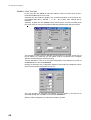
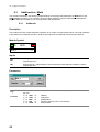
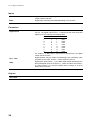
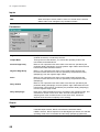
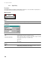
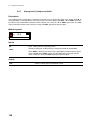
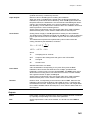
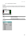
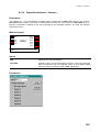
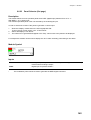
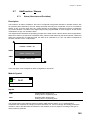
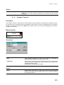
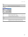
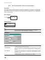
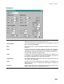
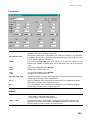
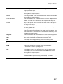
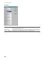
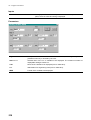
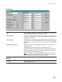
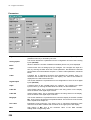
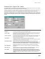
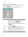
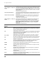
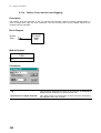
Label Off
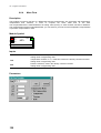
Inactive Status Label. This 3 characters label is the string shown on
the display, when the status of the digital input is inactive.
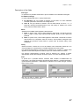
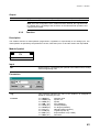
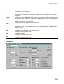
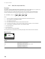
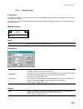
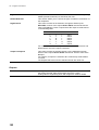
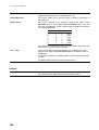
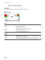
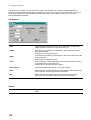
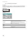
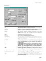
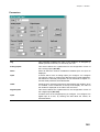
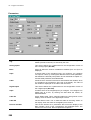
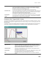
Process Variable
This section defines the 4 parameters that control the display of the
Main variable. Three of the 4 parameters are explained below. The
fourth one is the Format, that is explained at chapter 9.1
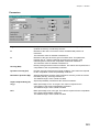
Label
Engineering units mnemonic. This string is the 3 characters
engineering units mnemonic of the Main Variable and it is shown in the
upper part of the display.
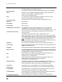
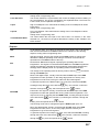
PV1Hi
High Range of PV1. This is the maximum value of the Main Variable.
Analog value in engineering units.
PV1Lo
Low Range of PV1. This is the minimum value of the Main Variable.
Analog value in engineering units.
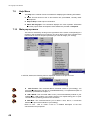
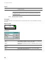
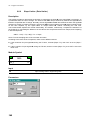
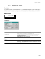
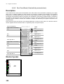
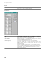
Local Set Point
This section defines the 3 parameters that control the display and the
handling of the Local Setpoint. Two of the 3 parameters are explained
below. The fourth one is the Format, that is explained at chapter 9.1
LspHi
High Local Setpoint. This value limits the setting of the Local Setpoint
to values lower than it.
Analog value in engineering units.
LspLow
Low Local Setpoint. This value limits the setting of the Local Setpoint
to values greater than it.
Analog value in engineering units.
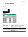
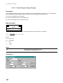
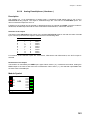
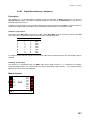
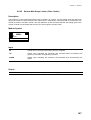
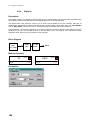
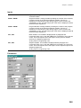
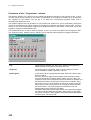
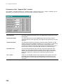
Bargraph 1
This section defines the characteristic of the scale of the bargraph 1
and the slider 1, related, respectively, to BI1 and CI1 analog input.
Max
High range of Bargraph. Analog value in engineering unit.
Min
Low range of the Bargraph. Analog value in engineering units.
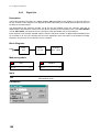
Bargraph 2
This section defines the characteristic of the scale of the bargraph 2
and the slider 2, related, respectively, to BI1 and CI1 analog input
Max
High range of Bargraph. Analog value in engineering unit.
Min
Low range of the Bargraph. Analog value in engineering units.
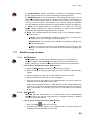
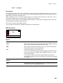
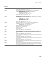
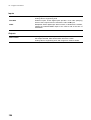
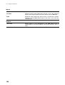
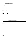
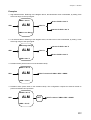
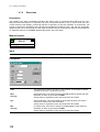
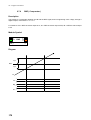
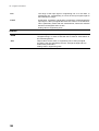
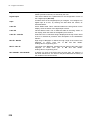
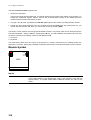
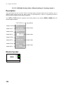
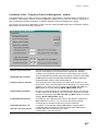
Outputs
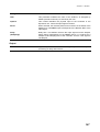
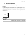
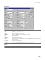
DA/M
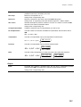
This output indicates the operating mode of the Out station:
- Active status = Manual operating mode
- Inactive status = Automatic operating mode
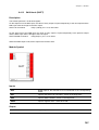
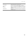
LSP
Local Setpoint value. This value, set through the front panel, is the
Local Setpoint that must be transmitted to the SDV module for the
selection of the Working setpoint.
Analog value in engineering units.
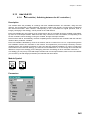
MOD
Special I/O signal, used by this module and the SDV module to change
and arbitrate the Setpoint operating mode change. It must be
connected to the equivalent I/O of the SDV module of the loop.
200