1
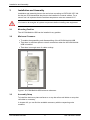
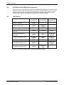
ACCON-NetLink-USB
User Manual
22-06-07, from FW 1.40
The best solutions for PLC
Copyright
© 1995 - 2007 by
DELTALOGIC Automatisierungstechnik GmbH
Stuttgarter Strasse 3
73525 Schwaebisch Gmuend
Germany
Phone sale:
+49-(0)7171-916-120
Phone support: +49-(0)7171-916-112
Fax sale:
Fax support:
+49-(0)7171-916-220
+49-(0)7171-916-212
E-Mail sale:
E-Mail support:
[email protected]
[email protected]
Web site: http://www.deltalogic.de
All rights reserved. No part of this work is allowed to be copied, reproduced,
conferred, processed and stored into electronic media or translated into any other
language without a written permission of the author.
Last update 2007-06-22. All technical changes reserved.
S7-200®, S7-300®, S7-400®, HMI®, STEP® and SIMATIC® are registered trademarks
of Siemens AG, ACCON® and DELTALOGIC® are registered trademarks of
DELTALOGIC Automatisierungstechnik GmbH.
ACCON-NetLink-USB
2
DELTALOGIC GmbH
Table of Contents
1
Table of Contents
1
Table of Contents .............................................................................................. 3
2
Safety Instructions ............................................................................................ 4
3
4
5
6
2.1
In General ................................................................................................. 4
2.2
Access Control.......................................................................................... 5
2.3
User Note.................................................................................................. 5
2.4
Appropriate Use ........................................................................................ 5
2.5
Avoid inappropriate Use............................................................................ 5
Installation and Assembly ................................................................................ 6
3.1
Mounting Position ..................................................................................... 6
3.2
Minimum Clearance .................................................................................. 6
3.3
Assembly Setup ........................................................................................ 6
System Overview ............................................................................................... 7
4.1
Use and Functional Characteristics .......................................................... 7
4.2
Connections .............................................................................................. 7
4.3
ACCON-NetLink-USB booting sequence.................................................. 8
4.4
LED Display .............................................................................................. 8
4.5
Scope of Delivery...................................................................................... 9
4.6
Accessory ................................................................................................. 9
Installing ACCON-S7-NET drivers.................................................................. 10
5.1
Introduction ............................................................................................. 10
5.2
System Requirements............................................................................. 10
5.3
Installation Setup .................................................................................... 10
5.4
Installation of USB driver ........................................................................ 12
Interface parametrization ................................................................................ 16
6.1
Bus Settings............................................................................................ 18
7
Troubleshooting .............................................................................................. 25
8
Appendix .......................................................................................................... 27
9
8.1
Connector Pin Assignment ..................................................................... 27
8.2
Technical Data ........................................................................................ 28
8.3
Updates on the internet........................................................................... 28
Table of figures ................................................................................................ 29
10 Table of charts ................................................................................................. 30
11 Index ................................................................................................................. 31
ACCON-NetLink-USB
3
DELTALOGIC GmbH
Safety Instructions
2
Safety Instructions
Please follow the indicated safety instructions for your own safety and others. They
are showing possible dangers and providing an indication of how to avoid them.
The manual in hand uses the following pictograms:
Hints and further information
Calls attention to dangers and sources of error
A general or specific danger
2.1
In General
The ACCON-NetLink-USB is only used as an element in a complete system.
In individual cases the operator of a machinery is obligated to follow the safety
regulations and the accident prevention regulations.
When projecting you have to follow the safety regulations and the accident
prevention regulation as the case arises.
According to EN 60204 / IEC 204 emergency stops have to remain active in all
machinery modes. Avoid undefined system restarts.
Errors appearing in the machinery which can cause damage to persons or material
have to be quenched by additional external mechanisms. In case of an error those
mechanisms e.g. electro-magnetic safety switches, mechanic lockings,etc. (look EN
954-1, risk analysis)have to guarantee for a save operating status.
Do not execute or initiate security-related functions via an operator terminal.
ACCON-NetLink-USB
4
DELTALOGIC GmbH
Safety Instructions
2.2
Access Control
As the assemblies are open operational equipment they have to be installed in
electrical operating areas, cabinets or cases only. It is important that they are only
accessible with a tool or a key by authorized or instructed staff.
Only authorized staff may have access to the assembly!
2.3
User Note
This guide is for planners, users and mechanics who are using the
ACCON-NetLink-USB.
This guide shows an operator the handling of the ACCON-NetLink-USB and
explains signaling functions. It also provides all necessary data for assembling.
The ACCON-NetLink-USB is intended for the exclusively use with Siemens
S7-200/S7-300 and S7-400 automation devices.
The ACCON-NetLink-USB is only used as an element in a complete system. For
this reason it is important that planners, users and mechanics are following
standards, safety regulations and accident prevention regulations for the respective
case of operation. Operators of automation systems are obligated to meet the
above-mentioned regulations.
When projecting you have to follow the safety regulations and the accident
prevention regulation as the case arises.
2.4
Appropriate Use
As already mentioned in the manual please use the ACCON-NetLink-USB as a
communication and signaling system only.
2.5
Avoid inappropriate Use
Do not control security related functions via the ACCON-NetLink-USB only.
Uncontrolled restarts are to be ruled out!
ACCON-NetLink-USB
5
DELTALOGIC GmbH
Installation and Assembly
3
Installation and Assembly
Installation and assembly have to be carried out according to VDE 0100 / IEC 364.
As they are IP30 assemblies they have to be installed in a control cabinet. For a
secure use it is important that the ambient temperature must not exceed 60 ºC.
You have to de-energize all system components before installing new equipment.
3.1
Mounting Position
The ACCON-NetLink-USB can be installed in any position.
3.2
Minimum Clearance
• To enable the assembling and disassembling of the ACCON-NetLink-USB
• That there is sufficient space to use all connections when the ACCON-NetLinkUSB is installed
• That there is enough room for cable routings
Figure 1: ACCON-NetLink-USB minimum clearance
3.3
Assembly Setup
To install the device on plane surfaces or on top hat rails a wall holder or a top hat
rail holder is necessary.
In chapter 4.6 you can find the available accessory with the respecting order
numbers.
ACCON-NetLink-USB
6
DELTALOGIC GmbH
System Overview
4
System Overview
4.1
Use and Functional Characteristics
The ACCON-NetLink-USB is a communication adaptor to access from a PC
PPI/MPI or Profibus via a USB port.
With only one USB connection (12 MBit/s-Fullspeed or 480 MBit/s-Highspeed) it is
possible to use up to twelve MPI-/Profibus connections (9,6 kBit/s to 12 MBit/s),
simultaneously.
With both USB and field bus the used baud rate can be calculated automatically,
(auto detect respectively auto baud function (automatic reconnaissance of netrelated parameters)).
The ACCON-NetLink-USB can either be sourced by a voltage feed of a PC's USB
port or by an external voltage feed.
A 1.2 m long power lead connects the ACCON-NetLink-USB to the automated
system. As the connecting plug is actively conducted there are no spur lines which
could interfere the bus.
4.2
Connections
• USB bushing (USB plug type B). To connect the device to usual PCs or hubs
using a standard USB 2.0 cable.
• Voltage supply bushing for feeding DC 24V.
This bushing has to be used if the USB port of a connected notebook or PC does
not have a sufficient voltage feed.
• Bus plug with a PG bushing, selectable terminator and a 1.2 m long connection
lead.
The 1.2 m long connection lead is decoupled by an active bus plug thus there is
no spur line and breakdowns with higher baud rates can be avoided.
Using the PG bushing you can attach additional users.
A terminator has to be inserted (ON) when the ACCON-NetLink-USB is attached
at the end or at the beginning of a bus segment. If not the switch position has to
be turned OFF.
ACCON-NetLink-USB
7
DELTALOGIC GmbH
System Overview
4.3
ACCON-NetLink-USB booting sequence
During the first seconds after the start the POWER LED lights green, the Active LED
and the Connect LED red. After a few seconds the Connect LED changes to green.
After the start activity has finished only the Power LED lights permanently green.
Thus the start activity is complete and the device is ready to operate.
4.4
LED Display
Power LED
Active LED
Connect LED
Ready to operate
GREEN
Trying to log on bus
GREEN
BLINKING
GREEN
Device is logged on the bus
GREEN
GREEN
Active connection to a
controller
GREEN
GREEN
GRÜN
Data exchange with a
controller
GREEN
GREEN
BLINKING
GREEN
BLINKING
GREEN
BLINKING
RED
BLINKING
RED
Store firmware update
GREEN
RED
RED
Bus-sided exception error
GREEN
PC-sided exception error
GREEN
Transmit firmware update
BLINKING
RED
BLINKING
RED
Table 1: LEDs on the upper side of the ACCON-NetLink-USB
ACCON-NetLink-USB
8
DELTALOGIC GmbH
System Overview
4.5
Scope of Delivery
• Ready for use ACCON-NetLink-USB
• 3m USB 2.0 cable
• DELTALOGIC Automatisierungstechnik-CD including ACCON-S7-NET driver
• User manual
4.6
Accessory
Top hat rail holder Item-No. 13012-HS
The top hat rail holder is required for mounting the ACCON-NetLink-USB on DIN
rails. No additional tool kits are required to separate the ACCON-NetLink-USB from
a top hat rail holder. To install the ACCON-NetLink-USB on plane surfaces it is
possible to channel the top hat rail holder into a wall holder by unscrewing the top
hat rail adapter.
Plug-in power supply unit 13012-24VDC
Input: AC 100-240 V / 50-60 Hz,
Output: DC 24 V / 330 mA
ACCON-NetLink-USB
9
DELTALOGIC GmbH
Installing ACCON-S7-NET drivers
5
Installing ACCON-S7-NET drivers
With installed ACCON-S7-NET drivers for the ACCON-NetLink-USB you can access
S7 controllers which have a PPI, MPI-/Profibus interface via USB.
5.1
Introduction
The ACCON-S7-Net latches into a PG/PC interface of an already existing Simatic
application and can be used with most Simatic Engineering-Tools (Step7, ProTool,
WinCC, etc.).You can access any Simatic S7-200, 300 and 400 series controller.
5.2
System Requirements
To use the ACCON-S7-NET driver on PG side a PC with Windows 2000 or
Windows XP as well as a Simatic-Engineering tool e.g. Step7 from Version 5.1
respectively STEP7-Micro/Win from Version 4.0 is required. By the installation of the
ACCON-S7-NET driver more interfaces are added to the PG/PC interface.
It is possible to install the ACCON-S7-NET driver under Windows 98/ME/NT but we
do not provide any support. And please take notice of the used Step7 requirements.
There have to be PCs with a working USB interface. Usual USB cards ca be used.
To achieve a good performance it is recommendable to use USB 2.0 (Highspeed
480 MBit/s). However it is possible to use Fullspeed USB interfaces (12 MBit/s) thus
the operating status is slowed down.
5.3
Installation Setup
After inserting the DELTALOGIC Automatisierungstechnik-CD please start the
ACCON-S7-NET driver setup. The SetupAcconS7Net.exe is located in the
»CD-drive:\ACCON-NetLink\S7-Treiber« directory.
You can download our latest ACCON-S7-NET drivers from our web site
www.deltalogic.de at no charge.
When installing drivers under Windows 2000 or Windows XP you need to log in as
administrator because the driver setup enrolls into the Windows registry.
Adding the interface to the PG/PC interface
After installing the driver for the first time the new interface parametrization
»ACCON-S7-NET NLUSB« has to be set up. Administrator rights are required.
Click on the »Select« button after starting »adjust PG/PC interface« in the control
panel.
ACCON-NetLink-USB
10
DELTALOGIC GmbH
Installing ACCON-S7-NET drivers
Figure 2: Adjust PG/PC interface
Then the dialog field »Install/Remove interface« appears.
Figure 3: Install/Uninstall Interfaces
After choosing the entry »ACCON-S7-NET NLUSB« on the left click on the »Install«
button.
ACCON-NetLink-USB
11
DELTALOGIC GmbH
Installing ACCON-S7-NET drivers
Thereupon the following inquiry appears:
»To go directly online with your installed interface you have to set the access path of
the access point of your application to the first interface parametrization.
Should S7ONLINE access ACCON-S7-NET NLUSB(MPI) now?«
If this inquiry is answered with »Yes« the ACCON-NetLink-USB will be directly set
as the acutal access path. When choosing »No« the previous access path remains
and the ACCON-NetLink-USB will be just added to the list.
After that the »ACCON-S7-NET NLUSB« appears in the right list with already
installed interfaces, too.
Choosing the desired interface parametrization
Now there are three additional ACCON-NetLink-USB entries in the interface
parametrization list.
Figure 4: Registered ACCON-S7-NET NLUSB
All important adjustments of the ACCON-S7-NET drivers can be made by clicking
on the »Properties« button. For further details please look for chapter 6.
5.4
Installation of USB driver
When connecting the ACCON-NetLink-USB to a PC for the first time the operating
system tries to install a suitable driver. This takes a bit time and continues as
follows.
ACCON-NetLink-USB
12
DELTALOGIC GmbH
Installing ACCON-S7-NET drivers
The operating system starts an installing wizard which guides you through further
mostly automatic procedures.
Figure 5: Installation start
The USB driver should not be selected automatically.
Figure 6: Installation method for driver
ACCON-NetLink-USB
13
DELTALOGIC GmbH
Installing ACCON-S7-NET drivers
Then you have to indicate the driver's source. It is sufficient to check
»CD-ROM drives«. Insert the DELTALOGIC Automatisierungstechnik-CD and click
»Next«.
Figure 7: Driver source
The driver should be found. Proceed with »Next«.
Figure 8: ACCON-NetLink-USB driver found
ACCON-NetLink-USB
14
DELTALOGIC GmbH
Installing ACCON-S7-NET drivers
After a successful driver installation you can finish the procedure by clicking on
»Finish«:
Figure 9: Installation completed
The ACCON-NetLink-USB has been installed and is ready for use. If there are
several ACCON-NetLink-USB devices available it is recommendable to copy the
USB drivers to your hard disk. Because for every ACCON-NetLink-USB there is a
single driver entity installed. Therefore the driver data is needed every time when
installing an ACCON-NetLink-USB. Remember that you cannot use more than one
ACCON-NetLink-USB on a single PC, simultaneously.
ACCON-NetLink-USB
15
DELTALOGIC GmbH
Interface parametrization
6
Interface parametrization
When choosing the ACCON-NetLink-USB in the »Adjust PG/PC interface« window
you can specify the access path by the »Properties« button.
The ACCON-NetLink-USB's access path properties are splitted into the following
parts:
• Bus Settings:
Here you can configure with which bus configuration (e.g. station address, baud
rate) the ACCON-NetLink-USB is reporting to the bus system.
• Options:
Here you can change the ACCON-NetLink-USB's driver language and readout
the driver’s version.
Figure 10: Bus settings
Diagnostics
When an ACCON-NetLink-USB is connected, the button »Diagnostics« gets visible.
Via this button you can determine the connected bus members as well as the actual
bus configuration.
For the diagnostics there are two subitems of the connected busses available.
Bus members
By clicking the »Read« button all active bus members are shown.
If supported by the connected devices you will get their ordering numbers when
activating the function »Read MLFB numbers«.
Depending on the settings in the PG/PC interface it is possible to determine the bus
members. It is recommendable to activate the function »automatic reconnaissance
of the net-related parameters« when using MPI and Profibus.
ACCON-NetLink-USB
16
DELTALOGIC GmbH
Interface parametrization
Figure 11: ACCON-NetLink-USB diagnostics, bus members
Bus parameter
If possible, the bus parameters of the actual connected bus will be determined when
clicking the »Read« button.
Figure 12: ACCON-NetLink-USB diagnostics, bus parameter
ACCON-NetLink-USB
17
DELTALOGIC GmbH
Interface parametrization
6.1
Bus Settings
The ACCON-NetLink-USB can be used with three different bus systems: PPI,MPI
and Profibus. From a user’s view the three bus systems only vary in the selectable
transmission rates and in the additional Profibus settings.
When operating the ACCON-S7-NET driver sends the bus configuration to the
ACCON-NetLink-USB. The device does not store this configuration.
It is possible to use the ACCON-NetLink-USB without indicating bus related
information.
In doing so the ACCON-NetLink-USB is able to determinate independently bus
parameters without changing the ACCON-S7-NET driver. It can be operated with
different automation systems if necessary with various transmission rates.
This function is supported when a participating automation system has activated
»Cyclic distribution of the bus parameters«
MPI Configuration
MPI configuration has station-related and net-related settings.
Assigning a station address is the most important setting. Meaning the address
which the ACCON-NetLink-USB should have when going online. The station
address can have any value in the range of »0« to »126« if the selected address is
less than or equal the highest number of users (HSA).
Example: HSA = 31
The station address can have any value in the range of »0« to »31« unless it does
not already exist at the bus. You can parametrize the local timeout of the ACCONNetLink drivers in the station-related settings. If there is no response to an inquiry
from the ACCON-NetLink-USB driver within a preset timeout; then the Simatic
application receives a communication error. When shortening the timeout you will
not get a reduction of the transmission time or an increase of the data throughput,
etc. . With net-related settings you have to adjust the transmission rate as well as
the HSA of the approached automation system.
ACCON-NetLink-USB
18
DELTALOGIC GmbH
Interface parametrization
Figure 13: Auto baud function deactivated, MPI
To simplify the configuration of station-related settings you can deactivate the auto
baud function.
Figure 14:Auto baud function activated, MPI
The functionality is not affected when using the auto baud mode but the initialization
of a connection lasts a bit longer as online parameters have to be determined at
first.
ACCON-NetLink-USB
19
DELTALOGIC GmbH
Interface parametrization
There are older Siemens CPUs which do not support the auto baud function.
Normally, PPI systems do not support the autobaud function, too.
Furthermore it is possible that the auto baud function does not work steadily with a
transmission rate less or equal 19,2 Kbit/s or when frequently communicating on the
basis of global data exchange. In this instance you should not determinate bus
parameters automatically.
Profibus Configuration
In principle, you have to do the same as you did during the MPI configuration but the
net-related parameters are more voluminous.
In addition to the already discussed parameters »transmission rate« and »highest
user addresses« there are »bus profile« and »bus parameters« with Profibus
available:
Figure 15:Auto baud function deactivated, Profibus
Profile:
Generally, there are three profiles when using Profibus:»DP«, »standard« and
»user-defined« You have to choose the profile which has been selected in the
automation system.
Bus parameters:
Unlike the bus profile MPI the bus parameters under Profibus are not constant and
vary in view of type and number of the utilized Profibus users.
It is recommendable that you always use the Profibus parameters which are already
adjusted in the automation system (look for Step7 project).
ACCON-NetLink-USB
20
DELTALOGIC GmbH
Interface parametrization
Figure 16: Extended parameter settings
To avoid these in part complex steps it is advisable to use the auto baud function
thereby the bus parameters will be determined automatically.
Figure 17:Auto baud function activated, Profibus
The function »Automatic reconnaissance of the net-related parameters« (autobaud
function) cannot be used when in the used PLC the function »Cyclic distribution of
the bus parameters« is not activated or supported e.g.:
- S7-200
- Older Siemens S7 CPUs
- ACCON-NetLink-USB is the only master on the bus
ACCON-NetLink-USB
21
DELTALOGIC GmbH
Interface parametrization
The following screenshot of a Profibus CPU shows the switch »Cyclic distribution of
the bus parameters«.
Figure 18: »Cyclic distribution of the bus parameters«
PPI Configuration
The most important setting is the station address. It is the address which the
ACCON-NetLink-USB has when going online. As long as the chosen address is
equal or less the highest participant address (HSA) the station address can have
any value in the range of »0« to »126«. But the address must not be on the bus.
The timeout indicates how long the communication driver should try to establish a
communication.
In the net-related settings the transmission rate and the highest participant address
must match with the accessed automation system.
Normally, the baud rate cannot be determined automatically on PPI busses!
ACCON-NetLink-USB
22
DELTALOGIC GmbH
Interface parametrization
Figure 19: Bus settings PPI
For more information regarding the use of Advanced PPI please look for the manual
of your S7-200 programming software.
The automatic detection of net-related parameters is not possible with S7-200
controls.
You have to activate Advanced PPI when communicating with a EM 277.
The PPI communication is supported from version 2.5 of the ACCON-S7-NET
driver. You need at least firmware version 1.4.
You will find actual drivers and firmware on our web site at www.deltalogic.de in the
section download/ACCON-NetLink.
ACCON-NetLink-USB
23
DELTALOGIC GmbH
Interface parametrization
Driver Options
Here you can select in which language the driver should output help and text
messages as well as the versions of the used driver data.
Figure 20: Language settings
Language Settings
You can select German or English. After you have switched the language please
call the settings window again to accept the changes.
Versions
Here you can find the driver data’s names and version. When requesting our
support it may be useful to provide the above-mentioned to check if you have
installed the correct versions.
For actual drivers and firmware versions visit our web site www.deltalogic.de and go
to the section download/ACCON-NetLink.
ACCON-NetLink-USB
24
DELTALOGIC GmbH
Troubleshooting
7
Troubleshooting
Q: I have connected the ACCON-NetLink-USB to my PC/notebook but it is rebooting
all the time.
A: It is possible that the voltage feed of your USB port is not sufficient enough so the
ACCON-NetLink-USB cannot work correctly. You can do the following things to
solve this problem:
•
Use an USB hub with an external voltage feed
• Or utilize an external voltage feed for the ACCON-NetLink-USB
Q: When I would like to use another ACCON-NetLink-USB or a different USB port of
my PC I have to install an USB driver again although I already used an ACCONNetLink-USB on this PC before.
A: In general, all USB devices have their own serial numbers so they can be
identified as a already known device. If you are using two USB units of the same
type there will be two driver instances installed on your PC, too.
The USB driver is located on the provided DELTALOGIC
Automatisierungstechnik-CD in the following directory
»CD-Drive:\ACCON-NetLink\S7-Treiber« or just download it from our web site
www.deltalogic.de.
Q: During the usage of an ACCON-NetLink-USB with an external hub or a separate
USB card unexpected errors occur. Disconnecting and reconnecting the USB
cable between ACCON-NetLink-USB and hub does not work.
A: When e.g. the power supply of the hub is too weak for the ACCON-NetLink-USB,
some of the hubs are reporting an error to the host system (PC). This triggers a
logical disconnection of the hub from the host. The host is not functioning
anymore. After a physical disconnect of the hub from the host and a reconnect to
the host; the hub should work again.
To solve the problem with the ACCON-NetLink-USB use an external power
supply for this device.
Q: I get an error message when accessing the controller.
A: Check the error message.
The problem may be the setting of the PG/PC interface (e.g. Profibus instead of
MPI, address already allocated, etc.) or the ACCON-NetLink-USB, for example, if
it is not connected or the necessary USB driver has not been installed, yet.
Q: There are no dialog settings in the Simatic Manager.
A: When you installed the ACCON-S7-NET driver for the first time you have to add it
to the PG/PC interfaces, too. Look for chapter 5 page 10-12.
Make sure that you have administrator rights when installing the driver. After a
successful installation you have to reboot your system.
Simatic Manager Version 5.1 is minimum!.
Q. When the adapter is plugged onto the Profibus, no online connection is possible.
A: If possible, use the autobaud functionality.
If not possible or not desired, check the timing parameters for the Profibus in the
STEP7 configuration. Enter the read values into the advanced bus parameter
settings via the »Bus parameters« button. If online access is still not possible, set
a higher »Ttr« (target rotation time) both in the ACCON-NetLink-USB and on the
CPU.
ACCON-NetLink-USB
25
DELTALOGIC GmbH
Troubleshooting
Q: The program Starter experiences difficulties when accessing a Micromaster
drive.
A: Please increase breakdown monitoring to 200ms and application monitoring to
5000ms.
Q: Every time I am executing a certain function it fails and the red Active and/or
Connect-LED is blinking.
A: Please contact our support and tell them how to trigger this error. We will try to
solve the problem as soon as possible.
Q: Sometimes MPI or Profibus connections with high baud rates are getting
disconnected although the ACCON-NetLink-USB is put on the CPU and no other
users are connected.
A: Be sure that the bus is scheduled properly.
Even though the ACCON-NetLink-USB is the only device connected to the bus in
addition to the CPU. You have to insert the final resistor. Above all high baud
rates can be interfered.
Q: When setting the ACCON-NetLink-USB to autobaud in the PG/PC interface and
try to go online, the active LED lights up briefly before a message appears telling
me that the bus parameters cannot be determined.
A: Please deactivate the autobaud function in the NETLink-S7-NET driver (PG/PC
interface). Then set the correct baud rate and the right profile.
Q: If I open various connections via the STEP7 driver, the connection sometimes
breaks off or error messages appear saying that it is not possible to establish a
connection.
A: For communication with S7-300 modules it may be necessary to parameterize
the communication resources.
You can influence the allocation of existing »Connection Resources« under
object properties of the CPU in the hardware configuration.
Q: Once the configured Profibus slaves have been added on my CPU,
communication between ACCON-NetLink-USB and STEP7 becomes markedly
slower.
A: You can influence the allocation of »Scan Cycle Load from Communication [%]«
under object properties of the CPU in the hardware configuration. The default
value is 20 %.
ACCON-NetLink-USB
26
DELTALOGIC GmbH
Appendix
8
Appendix
8.1
Connector Pin Assignment
MPI/Profibus Interface Assignment
Connection Signal
Meaning
1
-
unused
2
GND
Mass (looped through)
3
RxD / TxD-P
Received Data-P / Transmission Data-P
4
-
unused
5
DGND
Mass for bus scheduling (looped through)
6
DVCC
DC 5 V for bus scheduling (looped through)
7
VCC
DC 24 V (looped through)
8
RxD / TxD-N
Received Data-N / Transmission Data-N
9
-
unused
Table 2: Interface operation MPI/Profibus
USB Interface Assignment
Connection Signal
Meaning
1
VCC
DC 5 V
2
D-
Data -
3
D+
Data +
4
GND
Mass
Table 3: Interface assignment USB
The ACCON-NetLink-USB is supplied with a 3.0 m shielded USB 2.0 cable.
The cable has a USB plug type A and a USB plug type B.
It is important that the distance between two USB interfaces is not longer than 3 m
because the cable’s line voltage drop would be too big. When bridging longer
distances please use an USB hub.
Voltage Bushing
If you use an external voltage supply please look for a correct polarity and follow
technical data.
ACCON-NetLink-USB
27
DELTALOGIC GmbH
Appendix
8.2
Technical Data
Dimensions in mm (LxWxH)
102 x 54 x 30
Weight
ca. 180 g
Operating Voltage /
Power Input
DC 24 V ±25 %, 150 mA (ext.)
DC 5 V, 500 mA (USB)
selected automatically
USB Interface
USB 2.0 (Highspeed)
downward compatible to USB 1.1
USB Connection
USB plug type B
MPI/Profibus Interface
RS485, separated potentially
MPI/Profibus Transmission Rate
9,6 kBit/s;
45,45 kBit/s;
187,5 kBit/s;
1,5 MBit/s;
6 MBit/s;
MPI/Profibus Connection
SUB-D-Plug, 9-pole
with PG-Interface and a
terminating resistor
MPI/Profibus Protocols
FDL-Protocol for
MPI and Profibus
Display
3 LEDs, two bicoloured, for
general system information
Degree of Protection
IP 30
Operating Temperature
0°C ... 60°C
Storing and Transporting
Temperature
-20° C to +90°C
Relative Humidity Operating
5% to 85% at 30°C (no dew)
Relative Humidity Storage
5% to 93% at 40°C (no dew)
19,2 kBit/s
93,75 kBit/s
500 kBit/s
3 MBit/s
12 MBit/s
Table 4: The ACCON-NetLink-USB's technical data
8.3
Updates on the internet
You can find up to date drivers and firmware on our web site www.deltalogic.de in
the section download/S7-Adapter.
ACCON-NetLink-USB
28
DELTALOGIC GmbH
Table of Figures
9
Table of figures
Figure 1: ACCON-NetLink-USB minimum clearance................................................. 6
Figure 2: Adjust PG/PC interface ............................................................................. 11
Figure 3: Install/Deinstall interfaces ......................................................................... 11
Figure 4: Registered ACCON-S7-NET NLUSB........................................................ 12
Figure 5: Installation start......................................................................................... 13
Figure 6: Installation method for driver..................................................................... 13
Figure 7: Driver source............................................................................................. 14
Figure 8: ACCON-NetLink-USB driver found ........................................................... 14
Figure 9: Installation completed ............................................................................... 15
Figure 10: Bus settings ............................................................................................ 16
Figure 11: ACCON-NetLink-USB diagnostics, bus members .................................. 17
Figure 12: ACCON-NetLink-USB diagnostics, bus parameter................................. 17
Figure 13: Auto baud function deactivated, MPI ...................................................... 19
Figure 14:Auto baud function activated, MPI ........................................................... 19
Figure 15:Auto baud function deactivated, Profibus ................................................ 20
Figure 16: Extended parameter settings .................................................................. 21
Figure 17:Auto baud function activated, Profibus .................................................... 21
Figure 18: »Cyclic distribution of the bus parameters« ............................................ 22
Figure 19: Bus settings PPI...................................................................................... 23
Figure 20: Language settings................................................................................... 24
ACCON-NetLink-USB
29
DELTALOGIC GmbH
Table of Charts
10
Table of charts
Table 1: LEDs on the upper side of the ACCON-NetLink-USB.................................. 8
Table 2: Interface operation MPI/Profibus................................................................ 27
Table 3: Interface assignment USB ......................................................................... 27
Table 4: The ACCON-NetLink-USB's technical data ............................................... 28
ACCON-NetLink-USB
30
DELTALOGIC GmbH
Index
11
Index
Accessory.................................9
MPI Configuration .................. 18
Assembly..................................6
PPI Configuration................... 22
auto baud function....................7
Profibus Configuration ........... 20
Bus Settings ...........................16
Safety Instructions ................... 4
Connections .............................7
Scope of Delivery..................... 9
Installation ................................6
System Requirements ........... 10
Installation Setup....................10
Technical Data....................... 28
Language Settings .................24
terminator................................. 7
LED Display .............................8
USB bushing............................ 7
Mounting Position.....................6
USB driver ............................. 12
ACCON-NetLink-USB
31
DELTALOGIC GmbH