1
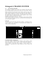
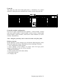
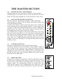
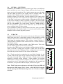
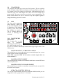
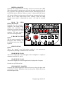
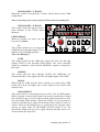
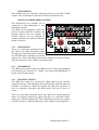
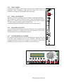
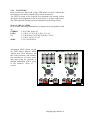
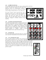
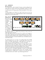
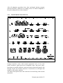
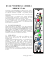
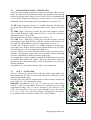
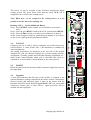
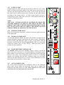
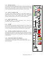
Octagonman.lwp
OCTAGON
(version1.2)
OWNERS MANUAL
Octagon page number 1
Octagon Manual
version: 1.1
Introduction and Product Overview
1.0
The Chassis system - description
1.1
Octagon chassis
2.0
Master section - description
2.1
Oscillator / Talk back section
2.2
Talk back section
2.3
Listen section
2.4
Studio 1 - 2 sections
2.5
2-Tracks
2.6
Solo section
2.7
Control Room Monitor section
2.8
Near fields
2.9
Dim
2.10 CRM switches
2.11 CRM mutes
2.12 CRM preset
2.13 CRM Dim / mutes
2.14 Main fader
2.15 Main LCD screen
2.16 Dynamics section
2.17 Console Recall / Reset
2.18 Joysticks
2.19 Communications
2.20 Control Monitor Matrix
2.21 Track ball
2.22 AUX.. Master section
2.23 Metering
2.24 Master Inputs / Outputs
3.0
"Dual-Path" mono module
3.1
Upper section
3.2
Equalizer section Upper path
3.3
Aux. 1-16 section
3.4
Pan pot
3.5
Insert
3.6
Dynamics
3.7
PHASE
3.8
AUTO
3.9
PFL
3.10 PEAK
3.11 Solo System
3.12 Fader Calibration
3.13 Group Control Display
Octagon page number 2
3.14
3.15
3.16
3.17
3.18
3.19
3.20
3.21
3.22
3.23
3.24
3.25
3.26
3.27
3.28
3.29
3.30
3.31
3.32
3.33
3.34
3.35
3.36
3.37
3.38
4.0
Select
Mute
Fader
Meter Read
Upper Routing Status section
Lower path
AUX. sends Lower path
Equalizer section Lower path
High Low pass Filter
LCRS Pan pot
Insert Lower path
Dynamics Lower path
PHASE Reverse Lower path
AUTO Lower path
PFL Lower path
PEAK Lower path
Safe indicator Lower path
SOLO System Lower path
Group control display Lower path
Ready switch
Select Lower path
MUTE Lower path
Fader
Upper & Lower path Inputs / Outputs
In / Output Module summary
The Dual Stereo return module
4.1
Input section
4.2
Equalizer section
4.3
AUX. send section
4.4
Stereo A/B Status Section - Using the Control Module
4.5
Equalizer section
4.6
Balance control
4.7
Stereo B Status Section - Using the Control Module
4.8
Auto
4.9
PFL
4.10 Solo
4.11 SEL
4.12 Mute
4.13 Fader
4.14 Upper Routing Status Section
4.15 Meter read
4.16 Lower path
4.17 LCR control
4.18 Remote
4.19 Stereo A/B status section - using the Control Module.
Octagon page number 3
5.0
Octagon’s Control Module
5.1
Group Busses
5.2
Input Selection
5.3
AUX. section
5.4
Pan pot assignment
5.5
Fader Calibration Upper path
5.6
SAFE (SIP) (Upper / Lower path)
5.7
Group Setup (Upper and Lower section)
5.8
LCR Lower path
5.9
ST-SRND ( Stereo-Surround) Lower path
5.10 Meter reads
5.11 Module Select section
5.12 Encoder
5.13 Copy
5.14 Menu
5.15 Show
5.16 Macro
5.17 Escape
5.18 Paste
5.19 All
5.20 Undo
5.21 Clear
5.22 Enter
5.23 Solo
5.24 Mute
5.25 Auto
5.26 Set-Up
5.27 Group Fader
5.28 Macro switches
6.0
MONITOR MATRIX MODULE
6.1
Patch bay description
6.2
Patch bay points
7.0
Instructions for operation
7.1
The Tracking session
7.2
The Playback session
7.3
The Overdub session
7.4
The Remix session
7.5
The MIDI or Virtual session
7.6
Surround mixing
7.7
Six Upper 5.1 DTS (Digital Theater Sound)
7.8
SDDS Film style mixing
8.0
Installation - electrical
8.1
Local Electrical Voltage
8.2
Electrical Wiring
Octagon page number 4
9.0
Installation - audio
9.1
Interface with Power Amps
9.2
The Initial Hookup
9.3
Shields & Grounds of Equipment
10.0
Troubleshooting and servicing
10.1 Troubleshooting
10.2 Removing a module
10.3 Patch bay - servicing
11.0
How to use the Octagon
11.1 Control Module
11.2 Setting up the Control Module
11.3 How to use the Control module
11.4 Group output switching
11.5 Input selection
11.6 Aux sourcing and assignment
11.7 Output assignment to master busses
11.8 Fader calibration (FDR CAL)
11.9 Safe
11.10 Lower pan LCR and Stereo surround
11.11 Fader Set
11.12 The Control Module Group master fader section
11.13 CGM solo
11.14 CGM Mute
11.15 CGM Auto
11.16 Meter reads
11.17 Control Module functions
11.18 Machine remote switches
11.20 Master section.
12.0
Connectors
12.1 Master section
12.2 Patch bay connectors
13.0
Specifications
14.0
Signal flow master section
15.0
Signal flow input module
16.0
Digital signal flow
17.0
Level diagram
18.0
Interfacing with DS4E / CP65
19.0
20.0
Interfacing with “Dolby” SEU4 / SDU4
Interfacing with JS 300
Octagon page number 5
21.0
Filmstyle mixing signal flow
22.0
Filmstyle mixing without Matrix
23.0
Filmstyle mixing setup
24.0
Filmstyle mixing with Matrix
25.0
Conformity statement according to ISO/IEC Nr. 22 and
EN 45014
26.0
Product safety
Octagon page number 6
Dear Octagon owner,
The Octagon was created using the latest in computer aided design and
assembling technology and incorporates the most advanced circuit
components available which results in the Octagon being another D&R
product unsurpassed in the electronics industry.
In D&R's quest to "raise the standard", Octagon is designed and
manufactured to the highest degree. We are confident that the Octagon
will play the central roll in producing "state of the art" recordings for
many years and wish you much success.
We value your suggestions and would appreciate you taking the time to
complete and return the questionnaire included at the front of this manual
(once you become familiar with your Octagon).
We listen and learn from your comments and you can be assured that our
research and development department will take your comments very
serious.
With kind regards,
Duco de Rijk
President D&R Electronica Weesp b.v.
RAISING
THE
STANDARD
Octagon page number 7
Octagon Recording Console
The D&R Octagon is a 48 buss, dual path in-line format recording and
film style mixing console designed to take the central role in a film sound
recording facility.
With up to 64 projects storable, the wasted time between sessions is a
thing of the past.
An essential part of the Octagon is its ability to record and mix down in
various output formats ranging from mono up to full SDDS formats.
With its digitally controlled software switches you can route any input in
the Octagon to a number of places and be able to recall all stored setups
by a couple of key strokes. This feature alone saves valuable time between
sessions.
A first in mixing console technology is Octagon's surround master section
with the ability to mix down a 7.1 surround, fully automated.
Easy monitoring of all surround outputs is standard and automated
Joysticks with Virtual Vision makes 360 degrees panning very easy to lay
down in the final mix.
Completely modular, Octagon can be configured precisely to suit your
particular system requirements. An Octagon standard is the internally
wired patch bay that interfaces with all external equipment using 25 pin
sub D connectors, and chassis mount XLR connectors.
To become completely familiar with your Octagon and gain the maximum
benefit from its use, we recommend that you read this manual thoroughly.
It will provide important information about all aspects of the Octagon
including; installation, operation, and servicing.
Head Office / Factory
D&R Electronica Weesp B.V.
Rijnkade 15B
1382 GS Weesp
The Netherlands
Tel: (-) 31 294 418 014
Fax: (-) 31 294 416 987
Website: http://www.d-r.nl
E-mail: [email protected]
Octagon page number 8
Octagon's CHASSIS SYSTEM
1.1
OCTAGON'S CHASSIS
The Octagon is available in two frame sizes; 60 and 84. The basic frame
has one blank module located on the extreme left of the frame. The two
blanks positioned left and right from the master section are part of the
master sections electronics and can not be replaced by input modules or
other equipment filling these positions. The blank on the far left side of
the frame cannot be replaced with an input module as they conceal
mechanical constructions and internal wiring.
Included with Octagon's frame are; the master section with associated
VU or LED peak metering, patch bay, all internal cable harnessing, and
rack mount power supplies.
Frame 60
The frame 60 will fit 60 dual path mono modules, a maximum of two
control modules and a maximum of 8 dual path stereo modules, the
master section, and patch bay.
Frame 60 standard configuration:
From left to right; 16 dual path mono modules, control module, 8 dual
path mono modules, master section, 16 dual path mono modules, a
control module, 8 dual path mono modules, a blank module and a
maximum of 8 dual path stereo return modules (16 stereo returns), and
patch bay.
Octagon page number 9
Frame 84
The frame 84 will fit 84 dual path mono, a maximum of 4 control
modules, 8 dual path stereo modules and a master section and patch bay.
Frame 84 standard configuration:
From left to right; 24 dual path mono modules, control module, 24 dual
path mono input modules, control module, master section, 24 dual path
mono modules, control module, 8 dual stereo return modules (16 stereo
returns), and patch bay.
Note: Octagon's patch bay can be ordered at either end of the frame
Delivery contents
In this shipment of your Octagon you will find the following parts, please
check and contact the factory immediately when something is missing.
1. Your configuration of the Octagon
2. Power supplies (2/3/4x analog, 1/2x motor- and 1/2x Logic power
supplies, depending on the size of your console)
3. Manual with software
4. Cables (Serial cable and 4 mains cables)
5. Powerfade software
6. PC display card
Octagon page number 10
THE MASTER SECTION
2.0
MASTER SECTION - DESCRIPTION
Octagon's master section is equivalent (in width) to 14 input modules.
All CRM outputs are located on the rear of the console below the meter
bridge. The following paragraphs give a brief description of each section.
2.1
OSCILLATOR/TALKBACK SECTION
The three frequency, low distortion oscillator is a phase shift design.
The frequencies are: 10kHz, 1kHz and 100Hz, each frequency has its own
front panel alignment trimmer.
A master level control is fitted to adjust the output of the oscillator for
precise alignment of the console and tape machines. The level ranges from
-10 dB to +10 dB with a detented mid-position of +4 dBu which can be
trimmed by the CAL trimmer. There is also a pink noise generator built in
for checking pan-pot movements and joystick routing.
The oscillator can be assigned to The master output busses, the Group
busses, the Aux/Joystick busses, as well as the direct output (in the patch
bay). Each of the oscillator assignment switches have a LED indicator.
The CRM will dim (adjustable in the software) when the oscillator is
active. (there is no -20dB attenuation when pink noise active) It is also
possible to cancel the dimming by activating the DIM switch when the
oscillator is active.
2.2
TALK BACK SECTION
A multi-way communication system is built into the Octagon.
The built-in talk back mic can feed Studio-1 output, Studio-2 output or
can be assigned to the routing by way of large push buttons positioned
right from the 8 track main fader. When Routing is selected the same
assignment switches as the for the oscillator can be used to further route
the talk back mic signal. The momentary TB talk back switch activates
the internal electret microphone.
2.3
LISTEN SECTION
Octagon has the ability to communicate with three independent rooms at
the same time or individually. Mic inputs are located on the back of the
console and are built around the same high quality mic pre-amps as the
console’s inputs. The communication buttons are located above the
TALK BACK switches in the Communications area. When one of the
Listen mics is activated, the internal Talk back mic will also be activated.
Octagon page number 11
2.4
STUDIO 1 - 2 SECTIONS.
STUDIO 1 and STUDIO 2 sections get their signal from several different
places and feed two sets of stereo outputs which are also located in the
master section of the patch bay. The 2 studio outputs can source the Aux.
3-4 and/or Aux. 1-2 and/or Left2- Right2, and/or Left-Right, and/or the
2 Tracks. The 2 Tracks switch needs a little more explanation.
With the Octagon, you can listen to stereo machines in the studio while
listening to the stereo lower outputs in the control room by pressing one
of the eight 2 track source switches and the 2 Tracks switch. By having
all the source switches in their up position no signal is fed to the Studio
systems. Aux. 1-2 and Aux.. 3-4 can be mixed (from the input modules)
and fed to the Studio 1, 2 or both outputs. With the 2 Tracks switch in
the down position, a selection can be made from any or all two track
source switches in the 2 Tracks section.
If you would like to build up a mix from one of the Aux. pairs, press Aux.
1-2 and or Aux. 3-4 switches. Studio 1, 2 or both can be used for stereo
headphone feeds or studio playback speakers.
2.5
2 TRACKS
Octagons 2 Track section allows you to select any or all 8 stereo 2 Track
inputs at the same time. A neat feature is that it is also possible to feed the
2 Tracks either from the main Left Right busses or from any other
2
Track input for copying purposes. This selection is made with the “2
TRACKS INPUT FROM” switch located below the 2 Tracks switches in
the 2 Tracks section.
An eight track return switch is located in the CRM section. This is also
the case with the general 2 Track source switching.
Just above the CRM level pot you find three switches labeled; MAIN to
CRM, 2 TRACK to CRM, and 8 TRACK to CRM. These are the main
selection sources for the CRM input. These switches have to be activated
first before any of the selected 2 Track sources will be heard.
The 2 Tracks can also be assigned to the near fields if desired. Its the
seventh switch in the upper row of switches located in the CRM section.
All tracks A through H are +4dBu. All of the 2 Tracks sources can be
summed if necessary. When sourcing 2 Track machines, all surround
CRM monitors will be switched off, unless the Decoder Active switch is
activated, then the 2 Track signal will be decoded into full surround and
all monitors, except for the Sub-bass output, will be active again.
Note: The 8 Track source selector as well as the 2 Tracks to CRM will
interrupt the CRM signal. The 2 Tracks A/B/C/D/E/F/G/H switches
will not interrupt the CRM monitoring unless the 2 Tracks to CRM is
activated!
Octagon page number 12
2.6
SOLO SECTION
The Solo section has a SOLO TRIM volume control and an AFL (after
fade listen) / SIP (Solo In Place) switch. A switch for momentary action
of all the SOLO switches and an Interlock switch for interlocking
behavior of all solo switches.
To easily cancel any activated SOLO switch in the entire console you just
have to hit the SOLO RESET button and all selected Solo's are canceled.
It is also possible to create SOLO presets of specific groups of solo
switches.
A maximum of three presets is possible. The SOLO 1/2/3 presets are
located in the Communication section of the Octagon.
The SOLO TRIM control has a center detent (for nominal level) built-in
to the volume control. With the AFL switch in its up position, the Upper
and Lower solo switches function in the PFL (pre fade listen) mode.
A lighting SOLO RESET switch in the communications section indicates
that a SOLO switch is depressed anywhere in the console.
If the AFL switch is depressed, any Solo switches function in the non
destructive after fade listen mode. If the Momentary switch is activated
Solo is only active when depressed. The Interlocking switch creates
canceling of previous selected solo switches, when selecting new solo
sources. SIP is possible with all three interacting modes such as
momentary, interlocking and adding.
2.7
CONTROL ROOM MONITOR SECTION
The CRM level controls a total of 8 outgoing levels to the control room
monitor power amps. This encoder controls all eight tracks with a superb
tracking and level repeatability. Attenuation of the CRM is always shown
in the LCD(isplay) in all levels of the menu. It ranges from 0dB down to
-75dB in 0.5dB steps and then it mutes the CRM completely.
The Octagon has a two by two CRM system intended for alternative
stereo near field monitors which are
switchable via the bank of switches located
above the CRM level controller.
Each alternate speaker system has its own
balanced XLR output for easy interchange
of near fields. The main eight CRM outputs
are on a 25 pole sub D connector. Also
fitted on the back of the master section are
the sub D connectors for the encoding and
decoding surround processors.
Octagon page number 13
2.8
NEAR FIELDS
The Octagon can handle two stereo near field systems. The two switches
on the far right of the CRM switch bank selects near fields to either the
LS1 outputs or the LS2 outputs, on which near field loudspeakers can be
connected. The near field outputs have their own level control and a
mono switch. The mono switch lets you check mono compatability. The
Mono switch allows the user to check for any out-of-phase signals or
simply monitoring your mix in mono.
2.9
DIM
The dim switch temporarily
dims Octagon's CRM level
by any user definable amount
of attenuation. This dimming
circuitry is also active when
the oscillator is turned on.
The LC Display shows the
amount of dimming when
activated.
2.10 MASTER/CRM
SWITCHES
The Octagon has a wide
range
of
possibilities
concerning its monitoring.
We shall describe any of the
two rows of switches individually located in the upper right corner of the
CRM section.
MASTER OUTPUT / SURROUND to MONO
This switch lets you convert the main stereo surround output into a mono
output signal on both surround outputs.
Note: This is not the CRM but the main surround outputs that are
mono summed!!!
MASTER OUTPUT INSERT
This switch globally switches all 8 balanced main inserts on and off from a
connected processor.
MASTER OUTPUT ENCODER INSERT
This switch lets you switch an eventually connected Encoder on and off in
the main 8 buss outputs.
8 TRACK to ROUTING BUSS 1-8
The 8 track returns normally fed to the CRM but with this switch you can
assign the 8 track to group busses 1-8 instantly.
Octagon page number 14
METER to MASTER
Normally the 8 output meters will follow all sources selected to the CRM.
When activated the 8 output meters will read the main outputs directly. In
the up position, all eight meters read the monitor CRM outputs prior to
the Encoder insert, when the "Meters to main" is depressed all the meters
will always follow the main outputs without being interrupted by the solo
system, the 2 Tracks and decoder active switches. When the Main
encoder insert switch is depressed the meters will read the encoded
signal.
SOLO TO NEAR
FIELD MONITOR
Normally the solo system is
assigned to the main monitor
system but activating this
switch let’s you listen to soloed
sources through the near field
monitors. The main monitors
will not be interrupted then.
2 TRACK TO NEAR
FIELD
All two tracks normally heard
though the main monitors can
be switched to the near fields if
required.
CRM TO NEAR
FIELD
This is the “regular” near field monitor switch if it is necessary to
comparatively listening to material on the near fields.
NEAR FIELD TO LS1
This switch assigns the near field signal to the Loudspeaker 1 outputs (it
alternates between LS1 and 2).
NEAR FIELD TO LS2
This switch assigns the near field signal to the Loudspeaker 2 outputs.
Second row of CRM switches
CRM SOURCE / MASTER
Normally the CRM loudspeakers follow all sources selected to them such
as Solo and 2 Tracks. When this switch is activated the CRM will listen to
the main outputs only.
Octagon page number 15
CRM SOURCE / 2 TRACK
When this switch is activated the 2 Tracks will be heard via the CRM
loudspeakers.
Note: a selection of one or more of the 2 Tracks need to be made first.
CRM SOURCE / 8 TRACK
This switch returns the outputs of the 8
track machine to the Control Room
Monitors.
CRM FORMAT
When no switches are active you will
have the 7.1 format.
5.1
This format switch let’s you assign the
CRM inner left and right signals (Left2 /
Right2) to the Left Right speakers.
Note: on CRM only!!!
LCRS
This format switch for the CRM only assigns the inner left and right
signals (L2/R2) to the left/right CRM outputs. The stereo Surround
signals are summed to mono and the SubWoofer outputs is assigned to
the center.
STEREO
This switch sums the inner left/right (L2/R2), the SubWoofer, the
Surround and the Center signals all to the left right outputs of the CRM.
MONO
When both the LCRS and the Stereo switches are activated the CRM
format will convert all signals into a mono signal on the control room
monitors only.
CRM INSERT 1
This switch inserts a connected processor in all of the 8 CRM outputs.
When a decoder is inserted this switch converts the encoded stereo signal
into a full Pro-Logic or circle Sound surround signal monitored over your
four (five/eight) CRM monitors. When this switch is in its On position a
normal or encoded stereo signal will be heard (If the encoder is active of
course). When no Decoding device is connected to the Octagon, there
will be no signal when the DECODER ACTIVE switch is on. The
Sub-Woofer output will not give a signal when the Decoder Active or 2
Track switches are depressed.
Octagon page number 16
CRM INSERT 2
This switch inserts an eventually connected processor in all of the 8 CRM
outputs. The second insert can be used to insert an academic filter.
CRM TO LOUDSPEAKER SYSTEM 1
The Octagon has two complete sets of
connectors to feed independent 8 way
monitoring systems.
The CRM can be assigned to either one
of these systems. Both the switches will
alternate between the two settings. (If
desired, software can be changed on
customer demand to be different from the
default software).
2.11 CRM MUTES
There is a total mute positioned below
the CRM level which completely mutes
all outgoing monitoring signals and there
are individual mutes, muting user selected
outputs only. These individual selected mute settings are kept in memory
when the total mute of the CRM is used temporarily.
2.12 CRM PRESET
The CRM preset switch returns the CRM level to a fixed preprogrammed
level necessary for reference of “Dolby” mix downs and adjustments of
studio control monitor amps.
2.13 CRM DIM / MUTES
The CRM dim switch let’s you dim the CRM output by any software
controlled amount. This dimming is also automatically activated when the
oscillator is switched on. When for instance the pink noise generator is
used for alignment procedures the DIM switch will not be active of
course.
There is a total mute positioned below the CRM level which completely
mutes all outgoing monitoring signals and there are individual mutes,
muting user selected outputs only. These individual selected mute settings
are kept in memory when the total mute of the CRM is used temporarily.
Octagon page number 17
2.14 MAIN FADER.
Located in the bottom of the master section is one 100mm PowerVCA
controlled fader controlling eight precision high end VCA's. Its
automation switches are located above the main fader.
2.15 MAIN LCD SCREEN
The main LCD screen displays most of Octagon’s automated functions.
The principal in working with this screen is that all functions and text
shown can be altered by the switch positioned below the character shown.
The Enter and Esc switches speak for themselves.
A detailed explanation will follow in later sections of this manual.
2.16 DYNAMICS SECTION
A gain reduction meter displays the gain reduction of the optional virtual
dynamics assigned to a signal path. (How the dynamics work will be
discussed later in a specific dynamics section).
2.17 CONSOLE RECALL / RESET
The Octagon has the ability to store all potentiometer positions and most
of all the switch settings except for the Oscillator, Talk back and all
functions positioned in the same “module” in the master section. These
functions are not necessary to be recalled in normal activities.
Octagon page number 18
2.18 JOYSTICKS
Both joysticks are fitted with a large LED matrix to easily visualize the
movements of the audio controlled by joystick movements.
The SETUP switch in the Joystick area determines the mixing format,
divergence and assignment to the 48 track buses or 8 main output buses.
The following basic formats can be programmed via the Setup switch.
Stereo, LCRS, 5.1, SDDS
In all formats individual combinations of outputs can be programmed such
as;
STEREO
L-R, L2-R2, Sl-Sr, off
LCRS
L-C-R-S, L-C-R, L-R, L-R-S, C-S, off
5.1
L-C-R-Sl-Sr,L-C-R,L-R,L-R,Sl-Sr, C-Sl-Sr,
L-C-R-S, L-R-S,C-S, off
SDDS
L-L2-C-R2-R-Sl-Sr-
Assignment LED's placed around
the LED matrix indicate which
outputs have been activated. All
the usual solo/mute and automation switches are of course available when using the joysticks. A
detailed explanation will be given
in the manual’s “How to ...”
section.
Octagon page number 19
2.19 COMMUNICATIONS
The communications section has three listen switches and three talk back
switches. The talk back switches are only active when
depressed, while the Communication switches are
latching and at the same time activate the Talk back
switch, making communication very easy either way.
The macro switches will be discussed later, they are
intended for fast access to often used functions and
setups. This is also the case for the SOLO 1 to 3
presets. The Solo reset cancels all active soloed
modules. The red light switch activates a relay built
inside the Octagon to felicitate external red light
signaling.
2.20 CONTROL MONITOR MATRIX
The control room monitor matrix is a built in remote unit to
control an optional Stems unit for extending the amount of
inputs when needed. A suggested grouping of Dialogue,
Music, Effects and Ambiance eases recognition of the
Stems that you are working with. A Mute, Solo, Direct and
Playback switches are controlling a complete group of
signals combined in a STEM / premix. A master
Direct/Playback switch controls all Stems in one go.
2.21 TOUCH PAD
The internal high quality touch pad needs to be connected
to the external PC that handles the Powerfade automation.
2.22 AUX. MASTER SECTION
The Aux. master section is located at the left side of the
master module and houses the 16 Aux. masters controlling
the output level of the Aux. sends. Each Aux. master has its own solo
switch. All Aux. master solo switches are AFL (after fade listen) switches
independent of the selection made in the SOLO control section. All mutes
are soft mutes and under control of the automation section. The Aux.
master pots are stored in the Recall system of the Octagon. The Aux.
outputs are balanced and normalled in the patch bay to the signal
processor inputs.
Octagon page number 20
2.23 METERING
Master metering
The Octagon has a total of eight VU meters or peak reading led bar
meters above the master section in the meterbridge. Analog VU meters
will indicate the average level in the signal paths and peak meters can be
switched between VU characteristics and peak behavior in the master
section.
A separate Phase meter indicates any phase shift between the left and
right signals. In most cases, switching the phase switch on selected input
modules can correct the phase shift.
Mono and Stereo
module meters
Due to the extreme
transients in digital
recordings,
Octagon's "Peak"
reading
upper
meters have an
extended
range
from -45dB up to a
reading of +6dB.
The bottom LED
on all D&R LED
bar graph meters is
an indicator that
the associated module is on. When first powering up, always check all
"ON" LED's under each meter.
If any "ON" LED is not lite, turn off the power supplies and call D&R for
service advice. Both mono and stereo input module meters have software
switch able peak/VU ballistics with 37 segments. Octagon's meters can be
switched (individually) to read the UPPER section or LOWER section of
each module locally.
The channel meters are of a peak or VU reading design and read 0dB
when an oscillator sine wave with a +4 dB output level is sent to the
meter in VU mode. Measuring the +4 dB output level of the upper or
master with a AC voltmeter would give a 1.22 AC volt reading.
When monitoring the oscillator on analog VU meters, the VU meters
should read "0" when the channel meters are reading 0dB. We have
discontinued the habit of making peak reading meters to read -6 dB down
from the actual output level for corresponding VU meter readings.
With more and more digital equipment being used for laying down tracks,
the actual level is of primary importance to know to avoid digital
overloads. But for engineers that are used to the “standard” way of
reading peaklevels a -6dB jumper is located on every meter that easily
converts the meter to the “classic” way of observing peak levels.
Octagon page number 21
After all alignment procedures have been performed, playing program
material will show a difference in reading on the VU meters compared to
the peak reading led bars in the channels.
2.24
MASTER INPUTS/OUTPUTS
Octagon interfaces easily with external equipment such as two track
master machines, signal processors, headphone amps, and power amps.
Interfacing is possible using the connectors on the master back panels, and
through 25 pole sub D male connectors. Listed below are all inputs and
outputs for the master modules.
The master back panel houses the connectors for interfacing with external
equipment.
Octagon page number 22
There are 5 rows of connectors.
The first row houses:
- Phones output (which is powered by the nearfield outputs).
- The balanced near field XLR outputs for easy interfacing with
personal monitors.
- The 8 buss CRM LS1 and CRM LS2 outputs for both control room
monitor systems.
- The connector for external connection of meters.
The second row houses;
- The mono surround trimpot
- The Pre Encoder out connector and the to Encoder connector.
- The CRM 1 and 2 insert send and returns.
The third row houses;
- Midi in / thru / out connectors.
- SMPTE in and outputs.
- RS422 connector to interface with the automation computer.
- Red light jack.
- Communication interface connector for machine control.
- Keyboard connector to be connected to the PC and the pointing device
(trackball/touch pad) connector to interface with the mouse output on
the external PC.
The fourth row houses;
- Spare connector for custom options
- Remote in and remote out connectors
The remote in let’s you externally control the CRM mute,the
Listen1/2/3 functions and the red light indicator.
The remote out sends control voltages of afore mentioned functions.
- Monitor connector coming from the internal TFT display.
The fifth row houses;
- The power supply connectors and chassis ground.
Below the master back panel are also the three Listen input XLR’s to be
connected to microphones positioned anywhere in the building.
A detailed connection diagram will be shown in the installation section of
the manual.
Octagon page number 23
DUAL PATH MONO MODULE
DESCRIPTION
The Octagon in/output module differs from all other modules because it
can be controlled from a Control Module. All switch functions that need
to be addressed immediately are available in every module. All switch
function that are set once or twice during a session are accessible via the
control module.
The SELECT switch in every in/output module “connects” its functions
of that module to the control module. At the same time the LED’s in the
control module indicates its present status and active switches.
In every module there are also LED's that indicate which function is
active, so at a glance you can see if a specific function is activated.
Pressing the SELECT switch further shows, in the Control Module, which
specific function has been activated.
3.0
DUAL PATH MONO MODULE
Octagon's Dual Path mono input module is a basic input / output design
whereby all signal flow takes place from the microphone to the multitrack.
Each dual path mono module is shipped with PowerVCA Automation
and a 37 segment LED bar graph meter. The mic/line inputs are in the
UPPER section of the module while the TAPE machine outputs are in
the LOWER section. The following sections explain the many functions
and features of each section of the dual path input module.
3.1
UPPER SECTION
Input selection of sources is done in the Control Module and can be
sourced from the MIC/LINE input, the Tape/Playback input or the
Group/Dir output.
The input section controls all incoming signals from microphone, line, and
multitrack outputs. A 48V phantom power switch for condenser
microphones or direct boxes can be silently switched in or out of the
circuit. The Line switch converts the Upper input from a balanced mic
input into a balanced line input. Octagon has separate electronics for each
input. The top knob of the dual concentric GAIN control adjusts the
mic/line levels in the UPPER path and the bottom control adjusts the
(tape) input of the LOWER path.
When the GAIN control is accurately set, it is possible to achieve the very
best signal to noise ratio and maximum headroom Octagon was designed
to achieve.
Octagon page number 24
3.2
EQUALIZER SECTION - UPPER PATH
This four-band parametric equalizer is unique in its design. There are four
bands, the high and low bands have sweep able frequency and shelving
characteristics type with a boost or cut of 16 dB. The two mid bands each
are sweep able frequency peak/dip type with a boost or cut of 16 dB and
bandwidth control which ranges from a maximum Q of 3 down to 0.5.
The HF (high frequency) section is a variable frequency shelving type,
sweep able from 4,000 Hz to 20,000 Hz with a max.. boost or cut of 16
dB.
The HMF (High / Mid Freq.) section has level and frequency controls
with variable frequency ranges from 600 Hz to 15,000 Hz and has a
maximum boost or cut of 16 dB.
The bandwidth has a Q factor ranging from 0.5 up to 1.5.
The LMF (Low / Mid Freq.) section has level and frequency controls
with variable ranges from 40 Hz to 1000 Hz and has a max. boost or cut
of 16 dB. The bandwidth has a Q factor ranging from 0.5 up to 1.5.
The LF (low frequency) section is a variable frequency shelving type,
sweep able from 10 Hz to 500 Hz with a maximum boost or cut of 16 dB.
The shelving curve can be switched into a Bell curve.
All level controls are center detented making neutral positions easy to
establish. All frequency ranges have been carefully selected following
extensive examination of all types of music (and noise).
Test comparisons of other equalizers helped the D&R design team create
an equalizer that sounds very musical , but at the same time, raising the
standard in specs and sound quality. Noise and distortion are kept to an
absolute minimum.
An equalizer on - off switch is fitted to allow easy comparisons.
3.3
AUX. 1 - 16 SECTION
All Aux. sends can be sourced from either the upper signal path or the
lower signal path. A LED on every module helps you to remind you of the
setting programmed locally.
All Aux. pairs have MUTE switches that are under software control and
part of the Power VCA automation system.
PRE/POST switching for Aux. 1 to 12 is done per pair in the control
module. A LED on every module helps you to remind you of the setting
programmed locally. Aux. 1/2 can be assigned to the routing as well.
AUX. 9/10 and AUX. 11/12 are per pair assignable to the Aux. busses
9/10, 11/12, 13/14, 15/16. All these settings are displayed in real time in
every module when a selection is made in the Control Module.
Octagon page number 25
The Auxes 1/2 can be assigned to the 48 busses through the digital
routing system. The green status LED indicates when AUX. 1-2 is
assigned to one or more of the routing busses
Note: When Aux. 1/2 are assigned to the routing busses, it is not
possible to use the busses for anything else
Routing AUX. 1 - 2 to the Multitrack Busses.
Step 1: Press SELECT on the module you would like to route auxes
from.
Step 2: Press the gray RTNG switch in the AUX. section labeled RTNG.
Step 3: Press the Buss switch or switches you would prefer to buss to.
Step 4: From Octagon's patch bay, patch the group outputs of your choice
to one of your signal processing equipment's inputs.
3.4
PAN POT
Octagon's pan pot is built to achieve minimum cross talk between two
selected busses. A center detent with -3 dB attenuation is standard for
stereo assignments.
All routing assignments are displayed at the left side of the module
alongside the pan pot showing instantly the present routing situation.
Assignment of routing formats and individual panning assignments are
made in the Control Module which will be described later when we
explain how to deal with the Control Module in day to day practice.
3.5
INSERT
Below the pan-pot the insert knob switches connected signal processors in
the signal path.
3.6
Dynamics
A local LED indicates that this part of the module is assigned to the
optional Dynamics package controlled in the master section. Comparisons
between treated and untreated signal is done in the master with the
Dynamics ON/OFF switch. When the green DYN LED is on, an optional
compressor, limiter, gate, or other effects / signal processors will be
inserted into the signal path.
Octagon page number 26
3.7
PHASE
The PHASE switch below the INSERT switch is used to reverse the
phase of any mic or line input. A successful method of checking for out of
phase signals is to press the mono switch on the master section and listen
closely to the lower. If an unexpected sound is heard or if something
appears to be missing from the lower frequency range, press the phase
switch on the upper suspected to be in error. If the sound improves, then
that upper was out of phase with the others.
3.8
AUTO
The AUTO switch determines the automation mode of the automated
fader. Either off (no LED's on) Read (R), Write (W) or Update/Trim both
Read and Write LED's on.
Note: These functions are only active when PowerVCA is loaded and
active on your PC!
3.9
PFL
The PFL switch has an adjacent LED as an indicator that it is activated.
This PFL switch is completely independent from the automated SOLO
system, but when a solo switch is activated in that channel it will be
turned off at the same moment.
3.10 PEAK
The PEAK led indicates any overload in the module 4 dB prior to clipping
from the following points. Pre-EQ, Post Insert, Post VCA.
3.11 SOLO SYSTEM
The Octagons solo system is very comprehensive. Various modes are
possible, PFL (pre fade listen), AFL (after fade listen) and SIP (Solo In
Place). Master status switching (located in the master section) selects the
PFL or AFL mode for the entire console (except for the Aux. master
solo's) and the Solo In Place mode. Solo In Place is a destructive solo
system muting all other channels except those that are in the Safe mode
(activated by the Safe switch).
Activating the PFL switch will send the pre fader signal of the Upper
section to the CRM speakers.
In the AFL mode (non destructive), the post modules pan pot signal is
heard, and all other modules are not muted within the stereo mix buss
Octagon page number 27
3.12 FADER CALIBRATION
When this LED is on, the upper motorfader is fixed positioned at unity
gain. This is very convenient when the upper section is used as a fixed
STEM return, which is normal practice for film style re mixes.
3.13 GROUP CONTROL DISPLAY
Fader, Solo, Mute and Auto(mation) functions can be grouped in control
groups up to a maximum of 8. The display shows to which control group
a specific module is assigned. How to do this will be explained in the
“How to ...” part of the manual.
3.14 SELECT
The Select switch is used for many purposes, but one of them is to assign
the module to the Control Module to be programmed as desired. At the
same time all LED's in the control module show the actual status of that
assigned input module. Changes are instantly without having to go to
extra store switches and the like.
3.15 MUTE
The MUTE system is a special soft-muting circuit, click-free and
associated with the automation circuitry.
3.16 FADER
The 100 mm linear motor fader controls the internal VCA. Today's VCA's
have very low distortion and very impressive specs, when the VCA is in
circuit, noise is kept to an absolute minimum and the ultra low distortion
is of the second (even) harmonic type responsible for a natural sound.
3.17 METER READ
The module’s Peak/VU led bar graph meter can be assigned to read the
input signal (Mic/Line) the Tape input signal or the Group output signal
of the module. Selection is made in the Control Module. It is also possible
to switch the ballistics of the meter between VU and Peak.
Octagon page number 28
3.18 UPPER ROUTING STATUS SECTION
There are 10 LED's positioned left of the upper pan pot that indicate the
basic routing of the upper section.
Every module shows locally that an assignment has been made yes or no
by way of an indicator LED. To know where the assignment has been
made to the SELECT switch has to be activated. The Control Module
shows in the routing section which buss is assigned to let you know what
is routed.
The upper status green LED's section shows the Left, Center, Right
assignments.
The yellow LED is on when the surround busses are assigned.
The red LED is on when the Sub Woofer is assigned
The next red LED indicates that the Left-2 and Right-2 output busses
have been assigned.
The yellow LED indicates assignment to the main Left Right busses.
The last three green LED's show assignment to the routing (busses) and
the Joysticks of the upper modules signal.
3.19 LOWER PATH
The LOWER section is the second signal path in the Octagon dual path
mono module. It has a full 4 band eq, and can access the 16 aux sends
too, insertable LCRS pan pot, and Mute & Solo switches. In record
mode, the LOWER section is fed by either the tape return or group
output. A master DIR/TAPE switch (a macro switch) selects either one of
the above.
3.20 AUX. SENDS - LOWER PATH
The lower path can use all of the 16 aux busses like the upper path.
Sourcing is controlled from the Control Module.
Aux. 1/2 & 3/4 were designed with a level and pan to build up a stereo
mix for headphones.
See for more details the description of the Aux. sends for the upper path.
3.21 EQUALIZER SECTION LOWER PATH
This four-band parametric equalizer is unique in its design. There are four
bands, the high and low bands have sweep able frequency and shelving
type boost or cut of 16 dB. The two mid bands are sweep able frequency
peak/dip type with a boost or cut of 16 dB and bandwidth control which
ranges from a maximum Q of 3 down to 0.5.
The HF (high frequency) section is a variable frequency shelving type,
sweep able from 4,000 Hz to 20,000 Hz with a max.. boost or cut of 16
dB.
Octagon page number 29
The HMF (High / Mid Freq.) section has level and frequency controls
with variable frequency ranges from 600 Hz to 15,000 Hz and has a
maximum boost or cut of 16 dB. The bandwidth has a Q factor ranging
from 0.5 up to 1.5.
The LMF (Low / Mid Freq.) section has level and frequency controls
with variable ranges from 40 Hz to 1000 Hz and has a max. boost or cut
of 16 dB. The bandwidth has a Q factor ranging from 0.5 up to 1.5.
The LF (low frequency) section is a variable frequency shelving type,
sweep able from 10 Hz to 500 Hz with a maximum boost or cut of 16 dB.
The shelving curve can be switched into a Bell curve.
All level controls are center detented making neutral positions easy to
establish. All frequency ranges have been carefully selected following
extensive examination of all types of music (and noise). Test comparisons
of other equalizers helped the D&R design team to create an equalizer
that sounds very musical, but at the same time, raising the standard in
specs and sound quality. Noise and distortion are kept to an absolute
minimum. An equalizer in - out switch with LED indicator is fitted to
allow easy comparisons.
3.22 HIGH LOWPASS FILTER
The Octagon has in its lower signal path a high and low pass filter with a
roll off of 12dB per octave.
The high pass filter has a range of 20 to 500 Hz and the Low pass filter
ranges from 4kHz up to 20kHz. An on/off switch is provided for
comparison of treated and untreated signal.
Octagon page number 30
3.23 LCRS PAN POT
Octagon's pan pot is built with special circuitry to allow for Left, Center,
Right, and Stereo Surround panning. The small upper control knob lets
you move the input signal from front (LCR) to rear. In the rear position
the signal can be panned between the surround left and right monitor
according to the format chosen. A LCRS switch toggles between a
normal pan-pot with -3dB center and a true LCRS pan-pot allowing for
complex positioning of sound.
NOTE:
THE LCRS / STEREO SWITCH IS CONTROLLED FROM THE
CONTROL MODULE. IF USED TO THE GROUP BUSSES THE
FORMAT SWITCHES LABELED MONO/STEREO/LCRS/5.1/SDDS
HAS TO BE ACTIVATED TO CREATE THE RIGHT PANNING
FORMAT PRIOR TO ASSIGNING TO THE BUSSES.
3.24 INSERT LOWER PATH
Below the pan-pot the insert knob switches connected signal processors
in the signal path.
3.25 Dynamics LOWER PATH
A local LED indicates whether this part of the module is assigned to the
optional Dynamics package controlled in the master section. Comparisons
between treated and untreated signal is done in the master with the
Dynamics ON/OFF switch. When the green DYN LED is on, an optional
compressor, limiter, gate, or other effects / signal processors will be
inserted into the signal path.
3.26 PHASE REVERSE LOWER PATH
The PHASE switch below the INSERT switch is used to reverse the
phase of any mic or line input. A successful method of checking for out of
phase signals is to press the mono switch on the master section and listen
closely to the lower. If an unexpected sound is heard or if something
appears to be missing from the lower frequency range, press the phase
switch on the upper suspected to be in error. If the sound improves, then
that channel was out of phase with the others.
3.27 AUTO LOWER PATH
The AUTO switch determines the automation mode of the automated
fader. Either off (no LED's on), Read (R), Write (W) or Update/Trim
both Read and Write LED's on. Note: These functions are only active
when PowerVCA is loaded and active on your PC!
Octagon page number 31
3.28 PFL LOWER PATH
The PFL switch has an adjacent LED as an indicator that it is activated.
This PFL switch is completely independent from the automated SOLO
system. However when a Solo switch is active and PFL is activated the
Solo switch will be inactive.
3.29 PEAK LOWER PATH
The PEAK led indicates any overload in the module 4 dB prior to
clipping. Measured is at pre-EQ, Post Insert and Post VCA positions.
3.30 SAFE INDICATOR LOWER PATH
SIP (Solo In Place) is a destructive solo system muting all other channels
except those that are in the Safe mode (activated by the Safe switch).
3.31 SOLO SYSTEM LOWER PATH
The Octagons solo system is very comprehensive. Various modes are
possible, PFL (pre fade listen), AFL (after fade listen) and SIP (Solo In
Place). Master status switching (located in the master section) selects the
PFL or AFL mode for the entire console (except for the Aux. master
solo's) and the Solo In Place mode. Solo In Place is a destructive solo
system muting all other channels except those that are in the Safe mode
(activated by the Safe switch).
Activating the PFL switch will send the prefader signal of the Upper
section to the CRM speakers.
In the AFL mode (non destructive), the post upper pan pot signal is
heard, and all other modules are not muted within the stereo lower buss.
3.32 GROUP CONTROL DISPLAY LOWER PATH
Fader, Solo, Mute and Auto(mation) functions can be grouped in control
groups up to a maximum of 8. The display shows to which control group
a specific module is assigned. How to do this will be explained in the
“How to ...” part of the manual.
Octagon page number 32
3.33 READY SWITCH
If wired to a tape machine that specific channel of the tape machine can be
put in “Ready” mode locally in the Octagon’s module without having to
reach for the tape machine’s remote control.It is done by way of midi
control messgaes and programmed in the Octagon’s master section.
3.34 SELECT LOWER PATH
The Select switch assigns the module to the Control Module to be
programmed as desired. At the same time all LED's in the control module
show the actual status of that assigned input module. Changes are
instantly without having to go to extra save switches and the like.
3.35 MUTE LOWER PATH
The MUTE system is a special soft-muting circuit, click-free and
associated with the automation circuitry.
3.36 FADER
The 100 mm linear motorfader controls the internal VCA. Today's VCA's
have very low distortion and very impressive specs, when the VCA is in
circuit, noise is kept to an absolute minimum and the ultra low distortion
is of the second (even) harmonic type responsible for a natural sound.
3.37 UPPER & LOWER PATH INPUTS / OUTPUTS
All mic inputs are interfaced via female XLR 3 pin connectors located on
the module back panels. All other module inputs and outputs are located
in the patch bay and accessible via 25 pin sub "D" connectors on the back
of the patch bay.
3.38 IN/OUTPUT MODULE SUMMARY
This description concludes the Octagon’s mono input module.
Specific how to use the module will be described later in the “How to ...”
part of the manual.
Octagon page number 33