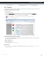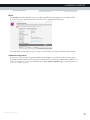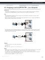
1
SETUP AND USER GUIDE MediaAccess TG789vn v3 SETUP AND USER GUIDE MediaAccess TG789vn v3 Copyright Copyright ©1999-2012 Technicolor. All rights reserved. Distribution and copying of this document, use and communication of its contents is not permitted without written authorization from Technicolor. The content of this document is furnished for informational use only, may be subject to change without notice, and should not be construed as a commitment by Technicolor. Technicolor assumes no responsibility or liability for any errors or inaccuracies that may appear in this document. Technicolor Delivery Technologies Belgium NV Prins Boudewijnlaan, 47 2650 Edegem Belgium http://www.technicolor.com Trademarks The following trademarks may be used in this document: AutoWAN sensing™ is a trademark of Technicolor. Adobe®, the Adobe logo, Acrobat and Acrobat Reader are trademarks or registered trademarks of Adobe Systems, Incorporated, registered in the United States and/or other countries. Apple® and Mac OS® are registered trademarks of Apple Computer, Incorporated, registered in the United States and other countries. Bluetooth® word mark and logos are owned by the Bluetooth SIG, Inc. DECT™ is a trademark of ETSI. DLNA® is a registered trademark, DLNA disc logo is a service mark, and DLNA Certified is a trademark of the Digital Living Network Alliance. Digital Living Network Alliance is a service mark of the Digital Living Network Alliance. Ethernet™ is a trademark of Xerox Corporation. Microsoft®, MS-DOS®, Windows®, Windows NT® and Windows Vista® are either registered trademarks or trademarks of Microsoft Corporation in the United States and/or other countries. UNIX® is a registered trademark of UNIX System Laboratories, Incorporated. UPnP™ is a certification mark of the UPnP™ Implementers Corporation. Wi-Fi®, WMM® and the Wi-Fi logo are registered trademarks of the Wi-Fi Alliance®. Wi-Fi CERTIFIED, Wi-Fi ZONE, Wi-Fi Protected Access, Wi-Fi Multimedia, Wi-Fi Protected Setup, WPA, WPA2 and their respective logos are trademarks of the Wi-Fi Alliance®. Other brands and product names may be trademarks or registered trademarks of their respective holders. All other logos, trademarks and service marks are the property of their respective owners, where marked or not. Document Information Status: v1.0 (April 2012) Reference: DMS-CTC-20101206-0033 Short Title: Setup and User Guide MediaAccess TG789vn v3 R10.2.x CONTENTS 1 Getting Started ......................................................................................................... 3 1.1 Features at a Glance ................................................................................................................................. 4 1.2 User Scenarios ............................................................................................................................................5 1.3 Components .............................................................................................................................................. 6 1.3.1 1.3.2 1.3.3 1.3.4 1.3.5 1.3.6 Power ................................................................................................................................................................................7 Local Network Connection........................................................................................................................................... 8 Broadband Connection ................................................................................................................................................. 9 Voice Connection ........................................................................................................................................................ 10 Buttons............................................................................................................................................................................ 11 Status LEDs ...................................................................................................................................................................12 1.4 Preparing for the Installation................................................................................................................... 15 2 Guided Installation................................................................................................... 17 3 Manual Installation................................................................................................... 21 3.1 Connecting the MediaAccess Gateway to your Service Provider’s Network ..................................22 3.1.1 Setting up your MediaAccess Gateway as DSL Gateway.......................................................................................23 3.1.2 Setting up your MediaAccess Gateway as Local Router ........................................................................................ 26 3.2 Powering on the MediaAccess Gateway ..............................................................................................27 3.3 Connecting Your Network Devices to the MediaAccess Gateway ................................................. 28 3.3.1 Setting up a Wireless Connection.............................................................................................................................. 29 3.3.2 Setting up a Wired Connection.................................................................................................................................. 30 3.4 Configure the MediaAccess Gateway .................................................................................................. 31 3.5 Setting Up the 3G Fall-Back WAN Connection..................................................................................32 3.5.1 Managing your Mobile Connection with the MediaAccess Gateway GUI...........................................................33 3.5.2 Inserting a Mobile USB Adapter ................................................................................................................................ 34 4 Configuration Tools.................................................................................................35 4.1 MediaAccess Gateway GUI ...................................................................................................................36 4.1.1 Access.............................................................................................................................................................................37 4.1.2 Components ................................................................................................................................................................. 38 4.1.3 Protecting Access to the MediaAccess Gateway ....................................................................................................40 4.2 Backing Up/Restoring your Configuration ...........................................................................................41 4.3 Access From the Internet....................................................................................................................... 42 5 The MediaAccess Gateway Wireless Access Point ............................................... 43 5.1 5.2 5.3 5.4 Connecting Your Wireless Client via WPS ......................................................................................... 44 Connecting Your Wireless Client without WPS ................................................................................. 46 Connecting Your Wireless Client via QR Code................................................................................. 47 Securing Your Wireless Connection..................................................................................................... 48 6 Telephony.................................................................................................................51 6.1 Setting Up Your Telephone Network ...................................................................................................52 6.1.1 Connection to the Traditional Telephone Network ................................................................................................ 53 6.1.2 Configuring the MediaAccess Gateway VoIP Service ........................................................................................... 54 DMS-CTC-20101206-0033 v1.0 i CONTENTS 6.2 Address Book........................................................................................................................................... 56 6.3 Telephony Services................................................................................................................................. 58 6.3.1 Activating a Telephony Service on your MediaAccess Gateway .......................................................................... 59 6.3.2 Common Telephony Services ....................................................................................................................................60 6.4 Viewing Call Logs ....................................................................................................................................63 7 Saving Energy ......................................................................................................... 65 7.1 Code of Conduct.................................................................................................................................... 66 7.2 ECO Manager..........................................................................................................................................67 7.3 Manually Switching Off Services to Reduce Power ........................................................................... 68 8 Sharing Content...................................................................................................... 69 8.1 The Network File Server ......................................................................................................................... 71 8.2 The UPnP AV Media Server ................................................................................................................. 74 8.2.1 Configuring the UPnP AV Media Server ................................................................................................................. 75 8.2.2 Using the UPnP AV Media Server ............................................................................................................................ 76 8.3 The FTP Server ........................................................................................................................................78 8.4 Managing your Shared Content............................................................................................................ 80 8.5 Safely Removing your USB Storage Device........................................................................................ 82 9 Network Services .................................................................................................... 83 9.1 UPnP......................................................................................................................................................... 84 9.1.1 9.1.2 9.1.3 9.1.4 Accessing Your MediaAccess Gateway via UPnP .................................................................................................. 85 Managing your Internet connection via UPnP ......................................................................................................... 86 Configuring UPnP on the MediaAccess Gateway .................................................................................................. 88 Installing UPnP on Windows XP ................................................................................................................................ 89 9.2 Assigning a service (HTTP, FTP,...) to a Computer...........................................................................91 9.3 Dynamic DNS ..........................................................................................................................................93 9.4 Network Time Server.............................................................................................................................. 94 10 Internet Security...................................................................................................... 97 10.1 Parental Control ...................................................................................................................................... 98 10.1.1 Configuring Content-based Filtering...................................................................................................................... 100 10.1.2 Adding Rules for Address-Based Filtering...............................................................................................................101 10.2 Firewall ....................................................................................................................................................103 10.3 Access Control.......................................................................................................................................105 10.4 Wireless Time Control..........................................................................................................................107 11 Support...................................................................................................................109 11.1 Setup Troubleshooting.......................................................................................................................... 110 11.2 General MediaAccess Gateway Troubleshooting.............................................................................. 111 11.3 Wired Connection Troubleshooting ....................................................................................................112 11.4 Wireless Connection Troubleshooting.................................................................................................113 ii DMS-CTC-20101206-0033 v1.0 CONTENTS 11.5 Voice over IP Troubleshooting ............................................................................................................ 114 11.6 Content Sharing Troubleshooting ....................................................................................................... 115 11.7 Reset to Factory Defaults ..................................................................................................................... 116 DMS-CTC-20101206-0033 v1.0 iii CONTENTS iv DMS-CTC-20101206-0033 v1.0 ABOUT THIS SETUP AND USER GUIDE About this Setup and User Guide In this Setup and User Guide The goal of this Setup and User Guide is to show you: Set up your MediaAccess Gateway and local network Configure and use the main features of your MediaAccess Gateway. For more advanced scenarios and features visit the documentation pages on www.technicolor.com. Used Symbols The danger symbol indicates that there may be a possibility of physical injury. The warning symbol indicates that there may be a possibility of equipment damage. The caution symbol indicates that there may be a possibility of service interruption. The note symbol indicates that the text provides additional information about a topic. Terminology Generally, the MediaAccess TG789vn v3 will be referred to as MediaAccess Gateway in this Setup and User Guide. Typographical Conventions Following typographical convention is used throughout this manual: This sample text indicates a hyperlink to a Web site. Example: For more information, visit us at www.technicolor.com. This sample text indicates an internal link. Example: If you want to know more about guide, see “About this Setup and User Guide” on page 1. This sample text indicates an important content-related word. Example: To enter the network, you must authenticate yourself. This sample text indicates a GUI element (commands on menus and buttons, dialog box elements, file names, paths and folders). Example: On the File menu, click Open to open a file. DMS-CTC-20101206-0033 v1.0 1 ABOUT THIS SETUP AND USER GUIDE 2 DMS-CTC-20101206-0033 v1.0 1 GETTING STARTED 1 Getting Started Introduction This chapter gives you a brief overview of the main features and components of the MediaAccess Gateway. After this chapter we will start with the installation. Do not connect any cables to the MediaAccess Gateway until instructed to do so. DMS-CTC-20101206-0033 v1.0 3 1 GETTING STARTED 1.1 Features at a Glance Introduction This section provides a brief overview of the main features of your MediaAccess Gateway. IPv6 Ready Your MediaAccess Gateway is IPv6 ready. Internet Protocol version 6 (IPv6) is the next generation of Internet technologies aiming to effectively support the ever-expanding Internet usage and functionality, and also to address security concerns that exist in an IPv4 environment. Internet connection features Broadband Internet access via the integrated DSL modem. The first chapters describe how to connect your MediaAccess Gateway to the Internet. Broadband Internet access via the Gigabit WAN port. The first chapters describe how to connect your MediaAccess Gateway to the Internet. 3G (Fall-back) High-speed Internet Access via the optional mobile USB adaptor. For more information, see “3.5 Setting Up the 3G Fall-Back WAN Connection” on page 32. Internet Security for your entire network. For more information, see “10 Internet Security” on page 97. Useful network tools like UPnP, Dynamic DNS and many more. For more information, see “9 Network Services” on page 83. Local networking features Wired access for your local network devices via the Ethernet interface. For more information, see “3.3 Connecting Your Network Devices to the MediaAccess Gateway” on page 28. Wireless access for your local network devices via the integrated IEEE 802.11n wireless access point. For more information, see “5 The MediaAccess Gateway Wireless Access Point” on page 43. An Integrated Media Server allowing you to share your media with media players and other network devices. For more information, see “8 Sharing Content” on page 69. Telephony features The MediaAccess Gateway offers Voice over IP (VoIP) connectivity for traditional phones and IP phones. For more information see “6 Telephony” on page 51 ECO label Technicolor’s ECO label guarantees you that the MediaAccess Gateway is able to reduce its power consumption to an absolute minimum. For more information, see “7 Saving Energy” on page 65. MediaAccess Gateway configuration tools 4 The MediaAccess Gateway Setup CD allows you to configure your MediaAccess Gateway and helps you to connect your computers to the MediaAccess Gateway. The MediaAccess Gateway GUI allows you to configure your MediaAccess Gateway via your web browser. For more information, see “4.1 MediaAccess Gateway GUI” on page 36. DMS-CTC-20101206-0033 v1.0 1 GETTING STARTED 1.2 User Scenarios Scenarios Depending of the architecture of your home network, you can use the MediaAccess Gateway in either of the following scenarios: DSL Gateway Local Router DSL Gateway The MediaAccess Gateway is connected to the DSL network of your service provider and brings the Internet to your home. Internet MediaAcces Gateway Local Router The MediaAccess Gateway is placed behind another gateway or modem. In this setup the gateway or modem in front of the MediaAccess Gateway will establish the connection to the Internet: Internet Modem/Router MediaAcces Gateway This scenario is used when: The Internet connectivity is provided by another device (for example, a cable modem). The MediaAccess Gateway is used to add specific services to your home network. Your service provider is using Ethernet in the First Mile (EFM). The Ethernet signal is directly coming into your home. Your service provider is using Ethernet To The Home (ETTH). MediaAccess Gateway is directly connected to the terminator of your service provider’s fiber-optic network and your local network DMS-CTC-20101206-0033 v1.0 5 1 GETTING STARTED 1.3 Components Overview This section provides an overview of the different components of the MediaAccess Gateway: Topic 6 Page 1.3.1 Power 7 1.3.2 Local Network Connection 8 1.3.3 Broadband Connection 9 1.3.4 Voice Connection 10 1.3.5 Buttons 11 1.3.6 Status LEDs 12 DMS-CTC-20101206-0033 v1.0 1 GETTING STARTED 1.3.1 Power Overview Power inlet The power inlet ( ) allows you to connect the power supply. Only use the power supply delivered with your MediaAccess Gateway. Power switch The power switch ( DMS-CTC-20101206-0033 v1.0 ) allows you to power on/off your MediaAccess Gateway. 7 1 GETTING STARTED 1.3.2 Local Network Connection Overview Wireless Access Point The built-in WiFi-certified wireless access point provides wireless access to your WiFi-certified wireless clients. For more information, see “5 The MediaAccess Gateway Wireless Access Point” on page 43. Ethernet switch The Ethernet switch ( ) allows you to connect an Ethernet device (for example, a computer) to your local network. For more information, see “3.3 Connecting Your Network Devices to the MediaAccess Gateway” on page 28. A LED may be provided per Ethernet port to indicate link integrity (or activity). LED Status Description Solid on Device connected. Blinking Device connected and sending/receiving data. Off No device connected. USB Port The USB port ( ) can be used to: Connect a USB mass storage device to share your content (for example, music, movies,...): On your local network via the Network File server or the UPnP AV Media Server. On Internet via FTP. For more information, see “8 Sharing Content” on page 69. 8 Connect a 3G mobile adaptor to set up a 3G connection that can work as a backup for your main Internet connection. For more information, see “3.5 Setting Up the 3G Fall-Back WAN Connection” on page 32. DMS-CTC-20101206-0033 v1.0 1 GETTING STARTED 1.3.3 Broadband Connection Overview DSL WAN DSL port This port can be used to connect your MediaAccess Gateway to your service provider’s DSL network. For more information, see “3.1 Connecting the MediaAccess Gateway to your Service Provider’s Network” on page 22. WAN port This port allows you to use your MediaAccess Gateway as Local Router. For more information, see “1.2 User Scenarios” on page 5. DMS-CTC-20101206-0033 v1.0 9 1 GETTING STARTED 1.3.4 Voice Connection Overview PSTN Phone Port The Phone ( ) port allows you to connect a traditional phone to your MediaAccess Gateway. This way you will be able to make phone calls over the Internet and save on communication costs, especially for long-distance calls. For more information, see “6.1 Setting Up Your Telephone Network” on page 52. PSTN Port (optional) The PSTN port allows you to connect the MediaAccess Gateway to the traditional telephone network, i.e. the Public Switched Telephone Network (PSTN). When the VoIP connection is not available, the MediaAccess Gateway will automatically switch from VoIP to the traditional telephone network. If your MediaAccess Gateway does not have a PSTN port, this means that: Your MediaAccess Gateways has an integrated filter The MediaAccess Gateway separates the phone signal from the signal coming from the DSL port. Your MediaAccess Gateway has an integrated filter if the product name printed on the label of your MediaAccess Gateway ends with “wIF” (with Integrated Filter). If this suffix is not present, then your MediaAccess Gateway does not have an integrated filter. - or Your MediaAccess Gateway is VoIP-only All calls passing through the MediaAccess Gateway will be done via VoIP. Be aware that, if you are not connected to the traditional telephone network, emergency calls will not be possible when your Internet connection is down or your MediaAccess Gateway is powered off. For more information, see “6.1.1 Connection to the Traditional Telephone Network” on page 53. 10 DMS-CTC-20101206-0033 v1.0 1 GETTING STARTED 1.3.5 Buttons Overview Reset WPS button The WPS ( ) button allows you to add new wireless clients to your network in a swift and easy way, without the need to enter any of your wireless settings manually. For more information, see “5.1 Connecting Your Wireless Client via WPS” on page 44. ECO button The ECO ( ) button allows you to disable your wireless access point. You can do this when you do not have any devices that are connected to the wireless access point. This allows you to save the energy that the MediaAccess Gateway would be using for the wireless access point. For more information, see “ECO button” on page 68. Reset button The Reset button allows you to reset your MediaAccess Gateway to factory defaults. For more information, see “11.7 Reset to Factory Defaults” on page 116. DMS-CTC-20101206-0033 v1.0 11 1 GETTING STARTED 1.3.6 Status LEDs Introduction On the front panel of your MediaAccess Gateway, you can find a number of status LEDs, indicating the state of the device. Power Ethernet USB Wireless Voice Broadband Internet TV Upgrade WPS Power LED Colour State Description Green Solid on Power on, normal operation Blinking Bootloader active (during upgrade) Red Solid on Power on, self-test failed, indicating device malfunction Orange Solid on Bootloader selftest Blinking Bootloader active (during upgrade) Off The MediaAccess Gateway is powered off. Ethernet LED Colour State Description Green Solid on Network device connected to the Ethernet switch. Blinking Network device connected to the Ethernet switch and sending/receiving data. Off 12 No Ethernet connection on your local network DMS-CTC-20101206-0033 v1.0 1 GETTING STARTED USB LED Colour State Description Green Solid on Device(s) connected to the MediaAccess Gateway’s USB port Off No device connected to the MediaAccess Gateway’s USB port Wireless LED Colour State Description Green Solid on No wireless activity, WPA2-PSK or WPA-PSK encryption Blinking Wireless activity, WPA2-PSK or WPA-PSK encryption Solid on No wireless activity, WEP encryption Blinking Wireless activity, WEP encryption Solid on No wireless activity, no security Blinking Wireless activity, no security Toggling Wireless client registration phase Orange Red Red/green Off Wireless access point disabled Broadband LED (if you are using the DSL Gateway scenario) Colour State Description Green Solid on DSL line synchronised Blinking Trying to detect carrier signal or pending DSL line synchronisation Off MediaAccess Gateway powered off. Broadband LED (if you are using the Local Router scenario) Colour State Description Green Solid on Connected to the WAN device Off Not connected to the WAN device Internet LED Colour State Description Green Solid on Connected to the Internet, no activity Blinking Connected to the Internet, sending/receiving data Solid on Failed to setup the Internet connection Red Off DMS-CTC-20101206-0033 v1.0 No Internet connection 13 1 GETTING STARTED TV LED Colour State Description Green Solid on Set-Top Box (STB) connected to the MediaAccess Gateway Blinking Unknown STB connected to the MediaAccess Gateway Off No STB connected to the MediaAccess Gateway Phone LED Colour State Description Green Solid on Registered at your VoIP provider, no activity. Blinking Registered at your VoIP provider, activity. Off Not registered to your VoIP provider. Upgrade LED Colour State Description Blue Solid on Software upgrade ongoing Off No software upgrade ongoing Do not power off your MediaAccess Gateway or disconnect any cables as long as the Upgrade LED is on. Interrupting the upgrade procedure may damage your MediaAccess Gateway. WPS LED Colour State Description Green Solid On Client successfully registered via WPS Orange Blinking WPS registration ongoing Red Blinking Error occurred For more information about WPS, see “5.1 Connecting Your Wireless Client via WPS” on page 44. 14 DMS-CTC-20101206-0033 v1.0 1 GETTING STARTED 1.4 Preparing for the Installation DSL service requirements This section is only applicable if you are using your MediaAccess Gateway as DSL gateway. For more information, see “1.2 User Scenarios” on page 5. Make sure that: Your service provider activated the DSL service on your telephone line by your service provider. You have the installation information (for example, user name, password, service profile,...) provided by your service provider at hand. Local connection requirements Wireless connection If you want to connect your computer using a wireless connection, your computer must be equipped with a WiFi-certified wireless client adapter. Wired connection If you want to connect a computer using a wired connection, your computer must be equipped with an Ethernet Network Interface Card (NIC). Start with the installation You are now ready to start with the installation of your MediaAccess Gateway. DMS-CTC-20101206-0033 v1.0 15 1 GETTING STARTED 16 DMS-CTC-20101206-0033 v1.0 2 GUIDED INSTALLATION 2 Guided Installation Introduction In the guided installation, the Setup wizard on the Setup CD will assist you with the installation of your MediaAccess Gateway. If you do not want to use the Setup CD or if the Setup CD is not included in your package, follow the installation procedure described in “3 Manual Installation” on page 21. Requirements To use the guided installation you must comply with the following requirements: Your computer must run one of the following operating systems: Microsoft Windows 7 and higher Microsoft Windows 7 x64 and higher Microsoft Windows Vista and higher Microsoft Windows XP Service Pack 2 (SP2) and higher Mac OS X 10.6 (Snow Leopard) Mac OS X 10.5 (Leopard) Mac OS X 10.4 (Tiger) You must have administrative rights on your computer. If you do not comply with these requirements, use the “3 Manual Installation” on page 21. Running the Setup wizard To start the Setup wizard: 1 Insert the Setup CD into your computer's CD- or DVD drive. 2 If your computer runs: Microsoft Windows: The Setup CD starts automatically. If the Setup CD does not autostart, see “The Setup CD does not start automatically” on page 110. Mac OS X: Double-click Menu in the window with the content of the Setup CD. 3 Select the language of your choice and click OK. 4 The Setup wizard will now guide you through the installation of your MediaAccess Gateway. DMS-CTC-20101206-0033 v1.0 17 2 GUIDED INSTALLATION 5 At the end of the installation, the following screen appears: Select Go to the Technicolor Gateway web interface if you want to go to the MediaAccess Gateway GUI after closing the wizard. On the MediaAccess Gateway GUI, you can configure all services of your MediaAccess Gateway. 6 Click Finish. 7 The CD menu appears. CD Menu On the CD Menu, you can click: Initial Setup to connect your computer to the MediaAccess Gateway and configure your local network. Reconfigure my Technicolor Gateway to fully reconfigure your MediaAccess Gateway. If you reconfigure your MediaAccess Gateway via the CD menu, the MediaAccess Gateway will be reconfigured from scratch. All your current settings will be lost. If you only want to make small changes to your configuration (for example, changing the security), we recommended you to do this via the MediaAccess Gateway GUI. For more information, see “4.1 MediaAccess Gateway GUI” on page 36. Setup my computer to connect your computer to the MediaAccess Gateway network. Documentation to view a list of the documentation that is available for your MediaAccess Gateway. Visit technicolor.com to visit the online support sections. Actual available items depend on the Setup CD delivered with your MediaAccess Gateway. 18 DMS-CTC-20101206-0033 v1.0 2 GUIDED INSTALLATION In case of problems If you encounter problems during this installation please refer to “11.1 Setup Troubleshooting” on page 110. Backup your configuration Once you successfully installed your MediaAccess Gateway, it is recommend to backup your configuration. This will allows you to return to this configuration when needed (for example, after misconfiguration). For more information, see “4.2 Backing Up/Restoring your Configuration” on page 41 DMS-CTC-20101206-0033 v1.0 19 2 GUIDED INSTALLATION 20 DMS-CTC-20101206-0033 v1.0 3 MANUAL INSTALLATION 3 Manual Installation Installation This chapter will help you to manually install your MediaAccess Gateway. Setting up your network Proceed as follows: 1 Connect your MediaAccess Gateway to your service provider’s network. For more information, see “3.1 Connecting the MediaAccess Gateway to your Service Provider’s Network” on page 22. 2 Power on the MediaAccess Gateway. For more information, see “3.2 Powering on the MediaAccess Gateway” on page 27. 3 Connect your computer to the MediaAccess Gateway. For more information, see “3.3 Connecting Your Network Devices to the MediaAccess Gateway” on page 28. 4 Configure your MediaAccess Gateway. For more information, see “3.4 Configure the MediaAccess Gateway” on page 31. 5 Connect your phones. For more information, see “6 Telephony” on page 51. 6 Share your content or media on your local network, continue with “8 Sharing Content” on page 69. 7 If you purchased the mobile USB adapter, setup the 3G backup connection. For more information, see “3.5 Setting Up the 3G Fall-Back WAN Connection” on page 32. 8 Once you successfully installed your MediaAccess Gateway, it is recommend to backup your configuration. This will allows you to return to this configuration when needed (for example, after misconfiguration). For more information, see “4.2 Backing Up/Restoring your Configuration” on page 41. DMS-CTC-20101206-0033 v1.0 21 3 MANUAL INSTALLATION 3.1 Connecting the MediaAccess Gateway to your Service Provider’s Network Identifying your setup If you are using the MediaAccess Gateway as: DSL Gateway, continue with “3.1.1 Setting up your MediaAccess Gateway as DSL Gateway” on page 23. Local Router, continue with “3.1.2 Setting up your MediaAccess Gateway as Local Router” on page 26. For more information, see “1.2 User Scenarios” on page 5, you can use your MediaAccess Gateway in either of the following scenarios 22 DMS-CTC-20101206-0033 v1.0 3 MANUAL INSTALLATION 3.1.1 Setting up your MediaAccess Gateway as DSL Gateway Introduction This section helps you to connect the MediaAccess Gateway to your service provider’s network. Signal arriving at your home The Line signal that arrives at your home consists the following components: A Phone signal carrying the traffic for telephony. This Phone signal is only used for communication over the traditional telephone network (PSTN). Voice over IP communication will be carried by the DSL signal. A DSL signal carrying the Internet traffic. DSL Gateways have a built-in solution to remove the Phone component. No additional devices are needed, you can connect them directly to the Line. Telephones do not have this capability, so here you have to use a filter or splitter to remove the DSL signal. What does a filter/splitter look like A splitter/filter is a box that typically has the following connectors: PHONE Service Provider Voice LINE DSL + Voice MODEM DSL + Voice Filter/Splitter A Line input This connector must be connected to the input signal that needs to be filtered. A Phone/PSTN output This connector offers filtered output signal. It only contains the Voice component and can only be used for connecting phones. A Modem/DSL output (optional) This connector offers unfiltered output. It contains both the Phone and DSL signal and can be used to connect your MediaAccess Gateway. Connecting the cables The procedure to be followed depends on the fact if this filter has been integrated into your MediaAccess Gateway or not. Check the label of your MediaAccess Gateway. If the product name contains: “wIF” (for example MediaAccess TG789vn v3 wIF) then your MediaAccess Gateway has an integrated filter. No external filters are needed. Follow the steps described in “Scenario 2: A MediaAccess Gateway without integrated filter” on page 24. No “wiF” (for example MediaAccess TG789vn v3) then your MediaAccess Gateway does not have an integrated filter. Follow the steps described in “Scenario 2: A MediaAccess Gateway without integrated filter” on page 24. DMS-CTC-20101206-0033 v1.0 23 3 MANUAL INSTALLATION Scenario 1: A MediaAccess Gateway with integrated filter Proceed as follows: 1 Take the DSL cable. This is the gray cable that is included in your box. 2 Plug one end of the cable in the grey DSL port on the back of your MediaAccess Gateway. DSL 3 Plug the other end of the cable: In the DSL/Modem output of your splitter/filter. Directly into the telephone wall outlet if there is no splitter/filter between the network terminator and your local phone network. Scenario 2: A MediaAccess Gateway without integrated filter Proceed as follows: 1 Take the DSL cable. This is the grey cable that is included in your box. 2 Plug one end of the cable in the grey DSL port on the back of your MediaAccess Gateway. DSL 3 Plug the other end of the cable into the DSL/MODEM output port of your filter/splitter. 24 DMS-CTC-20101206-0033 v1.0 3 MANUAL INSTALLATION If your MediaAccess Gateway has a black PSTN port on the back, you are able to use the PSTN (this is the traditional telephone network) as a backup for your Voice over IP connection. When the VoIP connection is down, the MediaAccess Gateway will automatically switch back to the PSTN network. To setup this backup connection: 1 Take a Telephone Cable 2 Plug one end of the cable in the black PSTN port on the back of your MediaAccess Gateway. PSTN 3 Plug the other end of the cable into the Phone output port of your filter/splitter. DMS-CTC-20101206-0033 v1.0 25 3 MANUAL INSTALLATION 3.1.2 Setting up your MediaAccess Gateway as Local Router Procedure Proceed as follows: 1 Take an Ethernet cable. If your box contains an Ethernet cable with red connectors, you can use that cable. 2 Plug one end of the cable in the red WAN port on the back of your MediaAccess Gateway. WAN 3 Plug the other end of the cable into the Ethernet port of your Internet gateway/modem. The WAN port can only be used to connect your MediaAccess Gateway to an Internet gateway/modem. You can not use it to connect other devices (for example, a computer) to the MediaAccess Gateway. 26 DMS-CTC-20101206-0033 v1.0 3 MANUAL INSTALLATION 3.2 Powering on the MediaAccess Gateway Procedure Proceed as follows: 1 Connect the power cord to the power port of the MediaAccess Gateway. 2 Plug the other end of the power cord into an electrical outlet. 3 Press the power button to turn on the MediaAccess Gateway. 4 Wait at least two minutes to allow the MediaAccess Gateway to complete the start up phase. DMS-CTC-20101206-0033 v1.0 27 3 MANUAL INSTALLATION 3.3 Connecting Your Network Devices to the MediaAccess Gateway Choose your connection method To connect your device via: 28 A wireless connection, continue with “3.3.1 Setting up a Wireless Connection” on page 29. A wired connection, continue with “3.3.2 Setting up a Wired Connection” on page 30. DMS-CTC-20101206-0033 v1.0 3 MANUAL INSTALLATION 3.3.1 Setting up a Wireless Connection The MediaAccess Gateway access point Your MediaAccess Gateway is equipped with a wireless access point that supports the following standards: IEEE 802.11n IEEE 802.11g IEEE 802.11b Requirements Your network device must be equipped with a WiFi-certified wireless client. Connection speed When setting up your wireless network, keep in mind that the following factors may have a negative impact on your wireless connection speed: The obstacles (walls, ceilings,...) between the wireless client and the access point. Distance between the wireless client and the access point. To fully benefit from the improved connection speed offered by the IEEE 802.11n standard, it is recommended to only connect IEEE 802.11n wireless clients to your MediaAccess Gateway. Connecting older (for example, IEEE 802.11g) wireless clients may also slow down connection speed of the IEEE 802.11n capable clients. If you have problems with your wireless performance, see “Poor Wireless Connectivity or Range” on page 113. To set up a wireless connections For more information on how to setup a wireless connection between your network device and your MediaAccess Gateway, see “5 The MediaAccess Gateway Wireless Access Point” on page 43. DMS-CTC-20101206-0033 v1.0 29 3 MANUAL INSTALLATION 3.3.2 Setting up a Wired Connection Requirements Both your network device (for example, a computer, a gaming console,...) and MediaAccess Gateway must have a free Ethernet port. Your network device must be configured to obtain an IP address automatically. This is the default setting. Ethernet cable In your package, you will find a cable with yellow connectors. This is the Ethernet cable. Procedure Proceed as follows: 1 Connect one end of the Ethernet cable to one of the yellow Ethernet ports of your MediaAccess Gateway: You can not use the red WAN port to connect to the local Ethernet network. The WAN port can only be used to connect your MediaAccess Gateway to your broadband source. For more information, see “1.2 User Scenarios” on page 5. 2 Connect the other end of the Ethernet cable to your network device. The MediaAccess Gateway does not support Power over Ethernet (PoE). All network devices that are connected to the MediaAccess Gateway must be powered by their own power source. 3 Your network device is now connected to your network. No additional configuration is needed unless specified by your service provider. 30 DMS-CTC-20101206-0033 v1.0 3 MANUAL INSTALLATION 3.4 Configure the MediaAccess Gateway Introduction If your service provider did not preconfigure your MediaAccess Gateway, you may have to configure the MediaAccess Gateway via its Graphical User Interface (GUI). Requirements JavaScript must be enabled on your web browser (this is the default setting). For more information, consult the help of your web browser. Procedure Proceed as follows: 1 Open your web browser. 2 The MediaAccess Gateway informs you that you have not yet configured your MediaAccess Gateway. If this window does not appear, browse to http://dsldevice.lan or to the IP address of your MediaAccess Gateway (by default: 192.168.1.254) and click Technicolor Gateway on the menu on the left-hand side. 3 Click Setup my Technicolor Gateway. 4 The Easy Setup wizard appears. This wizard will guide you through the configuration of your MediaAccess Gateway. Click Next and follow the instructions. DMS-CTC-20101206-0033 v1.0 31 3 MANUAL INSTALLATION 3.5 Setting Up the 3G Fall-Back WAN Connection Introduction Many SOHO (Small Offices, Home Offices) and SME (Small/Medium Enterprises) businesses choose DSL as their access technology for a Wide Area Network (WAN) connection because this is typically cheaper than using leased lines. A dropout of a DSL line can however have expensive consequences due to inaccessibility of the Internet and E-mail. Therefore backup solutions are available that provide an alternative path when the DSL line is down. For example it is possible to switch to 2G / 3G mobile access technologies such as GPRS, UMTS, HSDPA, HSUPA, HSPA+, WIMAX and LTE when internet connectivity is not available via the main WAN connection. By plugging a mobile USB adapter into one of the USB ports of your MediaAccess Gateway, IP connectivity via a 2G / 3G network becomes possible. 3G is an umbrella-term to indicate the third generation mobile telephony technology. The services associated with 3G provide the ability to transfer both voice data and non-voice data. 3G networks are the successors of the 2G networks, such as the GSM networks and provide new services and higher data transfer speeds. What do I need? To start using 2G / 3G as a connection on the MediaAccess Gateway, you need: A mobile USB adapter Only use the mobile USB adapters provided by your service provider. A registered Security Identity Module (SIM) card. Configure 2G / 3G as WAN connection Proceed as follows: 1 Configure your mobile connection. For more information, see “3.5.1 Managing your Mobile Connection with the MediaAccess Gateway GUI” on page 33. 2 Insert your mobile USB adapter. For more information, see “3.5.2 Inserting a Mobile USB Adapter” on page 34. 3 Now your mobile connection is up and ready to use. If you need to remove your mobile USB adapter, make sure the MediaAccess Gateway is powered off first. Result MediaAccess Gateway will automatically enable your 3G backup connection when both of the following conditions are met: The main Internet connection has been unavailable for at least 60 seconds. The MediaAccess Gateway received a request to access the Internet (for example, when browsing to an Internet web site). The MediaAccess Gateway will automatically disable the 3G connection in either of the following cases: 32 The main Internet connection is available again. In this case the MediaAccess Gateway switches back to the main Internet connection. No Internet traffic has been detected during the last 10 seconds. For example, you finished surfing the Internet. DMS-CTC-20101206-0033 v1.0 3 MANUAL INSTALLATION 3.5.1 Managing your Mobile Connection with the MediaAccess Gateway GUI Introduction You can view and manage the parameters of your mobile connection via the MediaAccess Gateway GUI. Procedure To manage your mobile USB connection via the MediaAccess Gateway GUI: 1 Browse to the MediaAccess Gateway GUI. For more information, see “4.1.1 Access” on page 37. 2 On the Broadband Connection menu, click Internet Services. 3 Click View more... for the mobile USB connection. The Overview page of the mobile USB connection is shown. 4 In the location bar, click Configure. The Configure page of the mobile connection appears. 5 Under Mobile Information, update the following fields if necessary: APN: The public APN used to access the Internet, or the private APN to access a local network. Operator Mode: 2G / 3G / automatic (let the MediaAccess Gateway choose the best operator mode) Pin: The PIN code of your SIM card. 6 Click Apply to apply your configuration changes. Configuration changes via the MediaAccess Gateway GUI are automatically saved. DMS-CTC-20101206-0033 v1.0 33 3 MANUAL INSTALLATION 3.5.2 Inserting a Mobile USB Adapter Procedure Once the mobile connection is configured you can proceed as follows to insert the mobile USB adapter: 1 Power off the MediaAccess Gateway. If you do not power off the MediaAccess Gateway first, the mobile USB adapter will not be detected. 2 Insert your SIM card into the mobile USB adapter. 3 Plug the mobile USB adapter in (one of) the USB port(s) of your MediaAccess Gateway: 4 Power on the MediaAccess Gateway. 34 DMS-CTC-20101206-0033 v1.0 4 CONFIGURATION TOOLS 4 Configuration Tools Configuration Tools You can use the following tools to configure your MediaAccess Gateway: The MediaAccess Gateway Setup CD allows you to configure your MediaAccess Gateway and helps you to connect your computers to the MediaAccess Gateway. For more information, see “2 Guided Installation” on page 17. The MediaAccess Gateway GUI allows you to configure your MediaAccess Gateway via your web browser. For more information, see “4.1 MediaAccess Gateway GUI” on page 36. DMS-CTC-20101206-0033 v1.0 35 4 CONFIGURATION TOOLS 4.1 MediaAccess Gateway GUI Introduction The MediaAccess Gateway Graphical User Interface (GUI) allows you to configure your MediaAccess Gateway using your web browser. Requirements JavaScript must be enabled on your browser (this is the default setting). For more information, consult the help of your web browser. 36 DMS-CTC-20101206-0033 v1.0 4 CONFIGURATION TOOLS 4.1.1 Access Accessing the MediaAccess Gateway GUI Proceed as follows: 1 Open your web browser. 2 Browse to http://dsldevice.lan or to the IP address of your MediaAccess Gateway (by default: 192.168.1.254). 3 If you have protected your MediaAccess Gateway with a user name and password, the MediaAccess Gateway will prompt you to enter these. Enter your user name and password and click OK. For more information, see “4.1.3 Protecting Access to the MediaAccess Gateway” on page 40. 4 The MediaAccess Gateway GUI appears. Access the MediaAccess Gateway via UPnP You can also access the MediaAccess Gateway GUI using the Internet Gateway Device (IGD) icon if your computer runs one of the following operating systems: Microsoft Windows 7 Microsoft Windows Vista Microsoft Windows XP For more information, see “9.1 UPnP” on page 84. Remote access It is also possible to access the MediaAccess Gateway GUI from the Internet. For more information, see “4.3 Access From the Internet” on page 42. DMS-CTC-20101206-0033 v1.0 37 4 CONFIGURATION TOOLS 4.1.2 Components Overview Depending on your user right and location on the GUI, the following components can be available: 3 2 4 5 1 6 7 Label Description 1 Menu 2 Login section 3 Language bar 4 Notification area 5 Navigation bar 6 Content pane 7 Tasks pane Menu The menu consists of the following menu items: Home: Allows you to go back to the MediaAccess Gateway home page. Technicolor Gateway: Provides basic information on the MediaAccess Gateway. Broadband Connection: Allows you to view/configure your broadband connections. Toolbox: Allows you to configure the network services and security settings of your MediaAccess Gateway. Home Network: Allows you to manage your local network. Help: Allows you to view context-related help information. Each of these items contain a number of sub-menu items. 38 DMS-CTC-20101206-0033 v1.0 4 CONFIGURATION TOOLS Login section In the login section you can see the current user name. By clicking the user name, you can: Change your password. Switch to another user. Language bar If more than one GUI language is available, a language bar is showed. This language bar allows you to change the language of the MediaAccess Gateway GUI. Notification area The notification area displays: Error messages, indicated by a red traffic light. Warning messages, indicated by an orange traffic light. Information messages, indicated by a green traffic light. If none of these events occur, the notification is not shown. Navigation bar The Navigation bar displays your current position in the MediaAccess Gateway GUI. Some page are available in different configuration levels. These pages have additional links (for example, Overview, Configure) in the right part of the navigation bar that allow you to switch between the configuration levels. Content pane The content pane displays the information and configurable items of the selected item. Tasks pane To allow a quick configuration of your MediaAccess Gateway, some pages may offer you a number of related tasks in the Pick a task list. These tasks will guide you to the page where you can perform the selected task. DMS-CTC-20101206-0033 v1.0 39 4 CONFIGURATION TOOLS 4.1.3 Protecting Access to the MediaAccess Gateway Introduction To prevent that every user on your local network can access the MediaAccess Gateway, the MediaAccess Gateway is secured with a user name and password. Default user name The default user name is Administrator. Default password The default password is either blank or the ACCESS KEY printed on the label of your MediaAccess Gateway. This depends on the settings chosen by your Service Provider. It is recommended to change the default password settings. Choose a password that your can easily remember or write it down. If you forget your password the only option is to reset your MediaAccess Gateway. For more information, see “11.7 Reset to Factory Defaults” on page 116. Protected items The following items are protected by these is will secure access to: The MediaAccess Gateway GUI. The embedded FTP Server. for more information, see “8.3 The FTP Server” on page 78. How to change your password Proceed as follows: 1 On the Toolbox menu, click User Management. 2 In the Pick a task list, click Change my password. 3 Enter your new password and click OK. 4 Your new password is now active. The next time that you log on to the MediaAccess Gateway GUI you will have to enter this password. This password will also be used by the network file server and FTP server. For more information about the network file server and FTP server, see “8 Sharing Content” on page 69 40 DMS-CTC-20101206-0033 v1.0 4 CONFIGURATION TOOLS 4.2 Backing Up/Restoring your Configuration Introduction Once you have configured your MediaAccess Gateway to your needs, it is recommended to backup your configuration for later use. This way you can always return to your working configuration in case of problems. Backing up your configuration Proceed as follows: 1 Browse to the MediaAccess Gateway GUI. For more information, see “Accessing the MediaAccess Gateway GUI” on page 37. 2 On the Technicolor Gateway menu, click Configuration. 3 In the Pick a task list, click Save or Restore Configuration. 4 Under Backup current configuration, click Backup Configuration Now. 5 The MediaAccess Gateway prompts you to save your backup file. 6 Save your file to a location of your choice. Do not edit the backup files, this may result in corrupt files making them worthless as configuration backup. Restoring your configuration Proceed as follows: 1 Browse to the MediaAccess Gateway GUI. For more information, see “Accessing the MediaAccess Gateway GUI” on page 37. 2 On the Technicolor Gateway menu, click Configuration. 3 In the Pick a task list, click Save or Restore Configuration. 4 Under Restore saved configuration, click Browse and open your backup file. Backup files usually have.ini as extension. 5 The MediaAccess Gateway restores your configuration. DMS-CTC-20101206-0033 v1.0 41 4 CONFIGURATION TOOLS 4.3 Access From the Internet Modes To access your MediaAccess Gateway from the Internet, you can choose between two modes: Permanent Mode (Remote Access): The remote session ends when you disable remote assistance or after restarting your MediaAccess Gateway. Temporary Mode (Remote Assistance): The remote session ends when you disable remote assistance, after restarting your MediaAccess Gateway or after 20 minutes of inactivity. To enable Remote Assistance / Remote Access. Enabling remote assistance is only possible when you are connected to the Internet. To enable remote assistance/access: 1 Browse to the MediaAccess Gateway GUI. For more information, see “Accessing the MediaAccess Gateway GUI” on page 37. 2 Complete and check the following parameters: Mode: Select the mode that you want to use. URL: Contains the URL that must be used to access the MediaAccess Gateway from the Internet. User name and Password: Contains the user name and password are needed to access your MediaAccess Gateway remotely. If wanted you can change the automatically generated password in the Password box. 3 Click Enable Remote Assistance. Accessing your MediaAccess Gateway from the Internet Proceed as follows: 1 Open your web browser. 2 Type the URL that was listed in the URL field on the Remote Assistance page (for example https://141.11.249.150:51003). You can replace the IP address in this URL by the dynamic DNS host name if you enabled and configured Dynamic DNS. For more information, see Dynamic DNS. Example: https://141.11.249.150:51003 can be replaced by https://mygateway.dyndns.org:51003. 3 Enter the user name and password that you specified on the Remote Assistance page. 4 The MediaAccess Gateway GUI appears. It is now possible for a remote user to access your MediaAccess Gateway via the specified URL using the provided user name and password. 42 DMS-CTC-20101206-0033 v1.0 5 THE MEDIAACCESS GATEWAY WIRELESS ACCESS POINT 5 The MediaAccess Gateway Wireless Access Point Introduction This section will help you set up your wireless network. What you need to set up a wireless network To set up a wireless network, you need the following components: A Wireless Access Point (already integrated into your MediaAccess Gateway) A Wireless client the device that you want to connect (for example, a computer, smartphone, network printer,...) Wireless Access Point The wireless access point is the heart of your wireless network. The wireless access point: Connects different wireless devices. Secures the data sent over wireless connection. The MediaAccess Gateway comes with an integrated wireless access point. Wireless client The wireless client allows you to connect a device, typically a computer, to a wireless access point. Both built-in and external (for example via USB) clients are available. Devices like media players and smartphones may also have a built-in wireless client. Check the documentation of your device for more information. Check the documentation of your computer if you are not sure if your computer is equipped with a wireless client. Configuring your wireless clients For more information on how to establish a wireless connection to the MediaAccess Gateway, see: “5.1 Connecting Your Wireless Client via WPS” on page 44 “5.2 Connecting Your Wireless Client without WPS” on page 46 “5.3 Connecting Your Wireless Client via QR Code” on page 47 Secure your wireless connection! When using an unsecured connection, everyone who is within the range of your MediaAccess Gateway can access your network. If not: People may use your connection to access the Internet. Hackers may use your connection to commit computer crimes. You can easily prevent this by securing your wireless access point. For more information, see “5.4 Securing Your Wireless Connection” on page 48. DMS-CTC-20101206-0033 v1.0 43 5 THE MEDIAACCESS GATEWAY WIRELESS ACCESS POINT 5.1 Connecting Your Wireless Client via WPS WPS Wi-Fi Protected Setup (WPS) allows you to add new wireless clients to your local network in a swift and easy way, without the need to enter any of your wireless settings (network name, wireless key, encryption type). Requirements Your wireless client must support WPS. Check the documentation of your wireless client for this. Both Windows 7 and Windows Vista Service Pack 1 have native WPS support. Your MediaAccess Gateway must use WPA(2)-PSK encryption (default encryption) or no encryption. WPS with WEP encryption is not possible. WPS Methods The following WPS methods are supported by your MediaAccess Gateway: Push Button Configuration (PBC): You have to put both your Wireless USB Adaptor and access point in registration mode. PIN code entry: You have to enter a PIN code on the Wireless Configuration Utility. Procedure for PBC Proceed as follows: 1 Shortly press the WPS button on the MediaAccess Gateway: 2 The WPS button LED starts blinking orange. This indicates that the MediaAccess Gateway is now searching for wireless clients that are in registration mode. You now have two minutes to start WPS on your wireless client. 3 Start WPS on your wireless client. 4 The MediaAccess Gateway is now exchanging the security settings. 5 At the end of the procedure the status of the WPS LED will change to either of the following: Solid green This indicates that you have successfully registered your wireless client. You are now connected to the MediaAccess Gateway network. 44 DMS-CTC-20101206-0033 v1.0 5 THE MEDIAACCESS GATEWAY WIRELESS ACCESS POINT Blinking red This indicates that the MediaAccess Gateway could not find your wireless client. Use the same procedure to try again (you do not need to wait until the LED turns off). Procedure for PIN code entry Proceed as follows: 1 Check the label on your MediaAccess Gateway and write down the following information: The PIN code that is printed next to the WPS logo. 1234-5678 The Network Name. This is the default network name (SSID). If you already configured a new network name, write down the new one. 2 Go the WPS PIN code page of your wireless client. 3 Enter the PIN code, Do not include the hyphen when entering the PIN code. For example, if your PIN code is 1234-5678, then enter 12345678. 4 Your wireless client may prompt you to select your access point. If this is the case, select the access point with the network name that you wrote down. Troubleshooting If you are having trouble connecting your wireless client via WPS, this may be cause by one of the following reasons: WPS can not be correctly executed: Configure your wireless manually. For more information, see “5.2 Connecting Your Wireless Client without WPS” on page 46. Your wireless client is out of range: If possible move your wireless client closer to your MediaAccess Gateway or use a wireless repeater to extend the range of your wireless network. Another device is interfering on the selected wireless channel: Change the wireless channel of your MediaAccess Gateway. For more information, see “Change the wireless channel” on page 113. DMS-CTC-20101206-0033 v1.0 45 5 THE MEDIAACCESS GATEWAY WIRELESS ACCESS POINT 5.2 Connecting Your Wireless Client without WPS Before you start Before you can connect a wireless client (for example, a computer) to your wireless network you need to know the wireless settings that are currently used by the MediaAccess Gateway, i.e.: The Network Name (SSID) The wireless key What Network Name (SSID) is my MediaAccess Gateway using? If you did not change the SSID, your MediaAccess Gateway uses the Network Name that is printed on the back panel label of your MediaAccess Gateway. What wireless key is my MediaAccess Gateway using? If you did not change the security settings, no wireless key is used. If your service provider did choose to use a default wireless key, use the Wireless Key that is printed on the bottom panel label of your MediaAccess Gateway. Forgot your wireless key? If you have changed the wireless settings manually and you can’t remember your settings, try one of the following: 1 Use a computer that is already connected to your network. If none of your computers is connected yet, connect one with an Ethernet cable. For more information, see “3.3.2 Setting up a Wired Connection” on page 30. 2 Browse to the MediaAccess Gateway GUI. For more information, see “Accessing the MediaAccess Gateway GUI” on page 37. 3 On the Home Network menu, click Wireless. 4 In the upper-right corner, click Details. 5 Under: Configuration, you can find the network name (SSID). Security, you can find the encryption. Connecting your wireless client Configure your wireless client with the same wireless settings as your MediaAccess Gateway (network name and wireless key). For more information, consult the documentation of your wireless client. 46 DMS-CTC-20101206-0033 v1.0 5 THE MEDIAACCESS GATEWAY WIRELESS ACCESS POINT 5.3 Connecting Your Wireless Client via QR Code Introduction The MediaAccess Gateway allows you to generate a Quick Response (QR) code that contains all wireless settings that are needed to connect. You are then able to connect to the wireless network by scanning the generated code. Target devices This connection method is typically used for tablet computers and smartphones. Requirements Your wireless device must have: A camera to scan the code. An application (app) to interpret the QR code and connect to a wireless network. For example: if you are using Android on your device, you could download Bar Code Scanner from Google Play. Procedure Proceed as follows: 1 Browse to the MediaAccess Gateway GUI. For more information, see “Accessing the MediaAccess Gateway GUI” on page 37. 2 Under Home Network, click Wireless. 3 Under Pick a Task, click Generate QR code image. 4 The wireless QR code appears. You can now: Scan the code directly from your screen. Print this page and scan the code from the paper version. 5 Your QR code app shows you the wireless settings used by your MediaAccess Gateway and offers you to connect to its wireless network. Connect to the network. DMS-CTC-20101206-0033 v1.0 47 5 THE MEDIAACCESS GATEWAY WIRELESS ACCESS POINT 5.4 Securing Your Wireless Connection Introduction You can protect the wireless communication between the wireless clients and your MediaAccess Gateway with a wireless key. This means that: Only clients which use the correct Network Name (SSID) and wireless key can connect to your network. All data passing through your wireless access point is secured and encrypted. Encryption types Over the years a number of encryption types have been developed. The list below gives you an overview of the supported encryption types ordered by descending security level; you will find the highest level of security at the top of the list: WPA-PSK Encryption: The wireless connection is secured with a pre-shared key that has been defined by the user. Wireless clients must be configured with this key before they can connect to the MediaAccess Gateway. The MediaAccess Gateway supports the following WPA-PSK versions (ordered by descending security): WPA2-PSK: The most recent and most secure version of WPA-PSK. Choose this version if you are sure that all your wireless clients support WPA2-PSK. WPA-PSK + WPA2-PSK: This is a mixed mode. In this mode WPA2-PSK, is the preferred encryption type but wireless clients do not support WPA2-PSK, can still use WPA-PSK as encryption type. Choose this option if not all of your wireless clients support WPA2-PSK or if you are not sure. Wireless clients that support WPA2-PSK will use WPA2-PSK, the others will use WPA-PSK. WPA-PSK: The first version of WPA-PSK. Choose this option if you are sure that none of your wireless clients support WPA2-PSK. If you want to configure WPA2-PSK on the built-in wireless utility of Windows XP Service Pack 2 (SP2), you first have to: Upgrade your Windows XP to Service Pack 3. - or Install the following update: http://support.microsoft.com/kb/917021. WEP Encryption: The least safe encryption type used for wireless connections. Like WPA-PSK it uses a user-defined key, but WEP has been proven to have security issues. Although the MediaAccess Gateway allows you to use WEP or no security, we strongly advise against using one of them! Use WPA(2)-PSK instead. Configuration Proceed as follows: 1 Browse to the MediaAccess Gateway GUI. For more information, see “Accessing the MediaAccess Gateway GUI” on page 37. 2 Under Home Network, click Wireless. 3 The Wireless Access Point page appears. In the upper-right corner, click Configure. 48 DMS-CTC-20101206-0033 v1.0 5 THE MEDIAACCESS GATEWAY WIRELESS ACCESS POINT 4 In the Security Mode list, select one of the following modes: WPA-PSK WPA2-PSK WPA-PSK + WPA2-PSK For more information, see “Encryption types” on page 48. 5 In the WPA-PSK Encryption Key box, type a the key of your choice. The key must be in one of the following formats: 8 to 63 alphanumeric characters. For example: MyKey123 8 to 64 hexadecimal characters (characters from 0 to 9 and from A to F). For example: C54F48A5. 6 Click Apply. 7 Reconnect your wireless client(s) to the MediaAccess Gateway using these new security settings. For more information, see “5.1 Connecting Your Wireless Client via WPS” on page 44 or “5.2 Connecting Your Wireless Client without WPS” on page 46. DMS-CTC-20101206-0033 v1.0 49 5 THE MEDIAACCESS GATEWAY WIRELESS ACCESS POINT 50 DMS-CTC-20101206-0033 v1.0 6 TELEPHONY 6 Telephony Voice over IP (VoIP) VoIP is a technology in which telephone calls are made over the Internet. This allows you to save on communication costs, especially for long-distance calls. The expensive solution To be able to make your phone calls over the Internet you could either: Buy an IP phone. These IP phones are special phones that you can connect to your Internet Gateway. Install VoIP software on your computer and make your phone calls via your computer. The Technicolor solution With the MediaAccess Gateway you can make both VoIP and traditional telephone calls using a traditional analogue phone. If your MediaAccess Gateway is not powered, the traditional telephone network (if connected) will automatically selected. This way you are still able to make emergency calls. In this chapter This chapter covers following topics: Topic Page 6.1 Setting Up Your Telephone Network 52 6.2 Address Book 56 6.3 Telephony Services 58 6.4 Viewing Call Logs 63 DMS-CTC-20101206-0033 v1.0 51 6 TELEPHONY 6.1 Setting Up Your Telephone Network Procedure To set up your telephone network, follow these steps: 1 Connect your traditional phone(s), DECT base station or fax to the green Phone port(s) on the back panel of your MediaAccess Gateway. 2 Connect your MediaAccess Gateway to the traditional network. For more information, see “6.1.1 Connection to the Traditional Telephone Network” on page 53. 3 Configure the VoIP service on your MediaAccess Gateway. For more information, see “6.1.2 Configuring the MediaAccess Gateway VoIP Service” on page 54. 52 DMS-CTC-20101206-0033 v1.0 6 TELEPHONY 6.1.1 Connection to the Traditional Telephone Network Combining VoIP with the traditional telephone network Some service providers use the traditional telephone network (PSTN) as a backup solution for your VoIP connection. This way, you can still make calls over the traditional network if the VoIP service is down (for example, your MediaAccess Gateway is powered off). Be aware that, if you are not connected to the traditional telephone network, emergency calls will not be possible when your Internet connection is down or your MediaAccess Gateway is powered off. Applicability If your MediaAccess Gateway: Has an integrated filter, no additional connections are needed. The DSL port must be directly connected to your telephone outlet. Do not put any filter or splitter between them! How do I know if my MediaAccess Gateway has an integrated filter? Check if the product name printed on the label of your MediaAccess Gateway ends with “wIF” (with Integrated Filter). If this suffix is not present, then your MediaAccess Gateway does not have an integrated filter. Does not have an integrated filter, check if your MediaAccess Gateway has a PSTN port on the back panel (for more information, see “PSTN Port (optional)” on page 10). If your MediaAccess Gateway has: A PSTN port: Connect the PSTN port to the Phone output of your filter or splitter. No PSTN port, no connections are needed. This is a VoIP-only variant. All calls passing through the MediaAccess Gateway will be done via VoIP. DMS-CTC-20101206-0033 v1.0 53 6 TELEPHONY 6.1.2 Configuring the MediaAccess Gateway VoIP Service Introduction If your VoIP service has not been configured yet, follow the instructions in this section. How can I check if the VoIP service has already been configured? If the Phone LED is: Solid or blinking green then the VoIP service is configured correctly. No configuration is needed. Off then telephony service is not configured (yet). Follow the instructions below. Requirements Your Internet connection must be up and running before you can configure Internet telephony. Configuring the VoIP settings Proceed as follows: 1 Enter the proxy and registrar settings. 2 Enter your VoIP account settings. Enter the proxy and registrar settings Proceed as follows: 1 Browse to the MediaAccess Gateway GUI. For more information, see “Accessing the MediaAccess Gateway GUI” on page 37. 2 On the Toolbox menu, click Telephony. 3 In the Navigation bar, click Expert configure. 4 Complete the following fields based on the settings provided by your VoIP provider: Proxy: Type the URL (for example: sip.provider.com) or IP address of the proxy. Registrar: Type the URL (for example: sip.provider.com) or IP address of the registrar. Registrar Port and Proxy Port. In most cases the default port (5060) will be used. Only change these values if your provider is using other port numbers. 5 Click Apply. Enter your VoIP account settings Proceed as follows: 1 In the Navigation bar, click Configure. 2 Under Service Configuration, select Enable Telephony. 3 Under Telephone Numbers, complete the following fields: SIP URI: The Uniform Resource Identifier (URI) of your SIP account (for example: 035051979, john.doe,...). This is the telephone number that people have to dial to call you. Username: The user name of your VoIP account (for example: 035051979, john.doe,...). 54 DMS-CTC-20101206-0033 v1.0 6 TELEPHONY Password: The password of your VoIP account. Displayname: The name that you want people to see on the display of their phone when you are calling. Your VoIP provider may not support this feature. Abbreviated number: An internal number to call the phones associated with this VoIP account. Port: The phone port that you want to associate with this VoIP account. select All to use this VoIP account for all connected phone. Phone 1/2 to use this VoIP account for the phone connected to the Phone 1/2 port of your MediaAccess Gateway. 4 Click Apply. Verifying Telephone Connectivity Proceed as follows to verify the voice connection: 1 Make sure the MediaAccess Gateway is turned on. 2 Make sure the Internet telephony service is enabled and configured. The Phone LED must be solid green. 3 Pick up your phone, wait for the dialling tone, and dial the number. DMS-CTC-20101206-0033 v1.0 55 6 TELEPHONY 6.2 Address Book Introduction The Address Book page allows you to: Store your contacts on the MediaAccess Gateway GUI. Initiate a call or send a message by clicking the phone number or e-mail address in the contact details. Everyone with access to the MediaAccess Gateway GUI can view and use the address book. Accessing the Address Book page Proceed as follows: 1 Browse to the MediaAccess Gateway GUI. For more information, see “Accessing the MediaAccess Gateway GUI” on page 37. 2 On the Toolbox menu, click Address Book. 3 The Address Book page appears. For each contact, you can provide the following information: Business: to make a call to the contact’s business telephone number Home: to make a call to the contacts home telephone number Mobile: to make a call to the contact’s mobile telephone number Other or SIP uri: to make a call to the contact’s VoIP telephone number E-mail to send an E-mail message to the contact with your e-mail client. Managing contacts Click... To... Add Add a contact Edit Edit a contact Delete Delete a contact All information provided per contact is optional except for the last and first name. The information can be updated or completed at any time. 56 DMS-CTC-20101206-0033 v1.0 6 TELEPHONY Making a phone call from the address book Proceed as follows: 1 Browse to the Address Book page. 2 Click on the phone number of your contact. 3 The following page appears: 4 Pick up the phone. 5 The MediaAccess Gateway is now initiating the call. Your contact’s phone is now ringing. 6 At the end of the conversation, click Done to go to the Last Calls page. This page allows you to view the statistics of your last calls (including the call that you just made). You can use the buttons in the Remote Number column to make a new call to one of the contacts in your call log. DMS-CTC-20101206-0033 v1.0 57 6 TELEPHONY 6.3 Telephony Services Introduction Telephony services add extra functionality to your phone. For example: putting a call on hold, transferring calls,... Requirements Before you can use a service, must both be: 1 Supported by your service provider. 2 Activated on your MediaAccess Gateway. Checking if a telephone service is activated/supported To check which services are supported or activated, proceed as follows: 1 Browse to the MediaAccess Gateway GUI. For more information, see “4.1 MediaAccess Gateway GUI” on page 36. 2 On the Toolbox menu, click Telephony. 3 In the Navigation bar, click Configure. 4 In the Pick a task list, click View Telephony Services. 5 Under Telephony Services, you can see the services that are supported by your provider. In the Activated column, you can see if this service is also activated on the MediaAccess Gateway. 6 To (de)activate a service, proceed with “6.3.1 Activating a Telephony Service on your MediaAccess Gateway” on page 59. 58 DMS-CTC-20101206-0033 v1.0 6 TELEPHONY 6.3.1 Activating a Telephony Service on your MediaAccess Gateway How can I (de)activate a service on my MediaAccess Gateway? You can (de)activate services in two ways: Via the MediaAccess Gateway GUI. Via (de)activation codes on your phone. Activating a Telephony Service via the MediaAccess Gateway GUI Proceed as follows: 1 Browse to the MediaAccess Gateway GUI. For more information, see “4.1 MediaAccess Gateway GUI” on page 36. 2 On the Toolbox menu, click Telephony. 3 In the Navigation bar, click Configure. 4 In the Pick a task list, click View Telephony Services. 5 In the Navigation bar, click Configure. 6 Under Telephony services you can now activate or deactivate the services of your choice: To: Activate a service select the check box next to the service. Deactivate a service clear the check box next to the service. 7 Click Apply. Activating a Telephony Service via Your Phone To (de)activate one of the services just dial the corresponding code on your phone. For example, to activate Call Hold dial *94; to deactivate the service dial #94. To know which code to use: 1 Browse to the MediaAccess Gateway GUI. For more information, see “4.1 MediaAccess Gateway GUI” on page 36. 2 On the Toolbox menu, click Telephony. 3 In the Navigation bar, click Configure. 4 In the Pick a task list, click View Telephony Services. 5 In the Telephony Services table, you can find the activation and deactivation codes. DMS-CTC-20101206-0033 v1.0 59 6 TELEPHONY 6.3.2 Common Telephony Services Introduction This section provides an overview of the functions that will be available if you activate one of the following services: Call Hold service Call Waiting service Conference Call (3 Party) service Call Transfer For more information on the other services, please contact your service provider. Call Hold service If the Call Hold service is activated, you can use the following functions: To... Press... Put an active call on hold and enable a call set up (the dial tone is generated) R, 2 Illustration A A B You press R, 2 active on hold dial tone You Terminate the call on hold R, 0 A You A B on hold active You press R, 0 R, 1 A You A B on hold active R, 1 A active You A B You press R, 1 on hold R, 9 A You on hold You 60 A B active B active You Terminate an active call and enables a call set up (the dial tone is generated) B You press R, 1 You Retrieve the call on hold (when there is no active call) B active You Terminate an active call and switch to the call on hold B B You press R, 9 on hold dial tone You DMS-CTC-20101206-0033 v1.0 6 TELEPHONY Call Waiting service If the Call Waiting service is activated, you can use the following functions: To... Press... Terminate an active call and switch to an incoming call R, 1 Illustration A A B active incoming active You You Reject an incoming call R, 0 A A B incoming active You press R, 0 R, 2 A You B on hold active You press R, 2 A B on hold active You You Switch between an active call and an incoming call R, 2 A B active B active You Switch between an active call and a call on hold B You press R, 1 incoming You press R, 2 A B on hold active You You Conference Call (3 Party) service If the Conference Call (3 Party) service is activated, you can use the following functions: To... Press... Establish a conference call (or 3 party connection) R, 3 Illustration A B active on hold You press R, 3 A B active active You You During a conference call: put B and C on hold R, 2 A B active active You press R, 2 A B on hold on hold You You During a conference call: retrieve B and C when they are on hold R, 3 A B on hold on hold You DMS-CTC-20101206-0033 v1.0 You press R, 3 A B active active You 61 6 TELEPHONY Call Transfer If the Call Transfer service is activated, you can use the following functions: To... Press... Transfer a call R, 4 Illustration A active on hold You 62 A active B B You press R, 4 You DMS-CTC-20101206-0033 v1.0 6 TELEPHONY 6.4 Viewing Call Logs Introduction The Call Logs page on the MediaAccess Gateway GUI lists: Successful incoming calls. Missed incoming calls. Successful outgoing calls. Failed outgoing calls. Viewing the telephony statistics Proceed as follows: 1 Browse to the MediaAccess Gateway GUI. For more information, see “Accessing the MediaAccess Gateway GUI” on page 37. 2 On the Toolbox menu, click Telephony. 3 The Telephony page appears: On this page you can see an overview of your last calls. 4 To view more detailed statistics, click View telephony statistics and logs in the Pick a task list. Used icons The call logs use the following icons to illustrate the call type: Icon Type Successful outgoing phone call Successful incoming call Failed outgoing call Failed incoming call Calling a contact from the call log You can immediately start a new call to one of these contacts by clicking the button in the Remote Number column. DMS-CTC-20101206-0033 v1.0 63 6 TELEPHONY 64 DMS-CTC-20101206-0033 v1.0 7 SAVING ENERGY 7 Saving Energy Code of Conduct To prove its commitment to protect the environment, Technicolor has signed the Code of Conduct, a global agreement to reduce the power consumption of broadband access devices. For more information, see “7.1 Code of Conduct” on page 66. Technicolor power saving innovations To further reduce the power consumption, Technicolor has developed the ECO Manager. This system constantly monitors the services provided by the MediaAccess Gateway and automatically switches unused services to an ECO-friendly state. For more information, see “7.2 ECO Manager” on page 67. Next to this automated tool, you can also choose to manually disable services that you will not be using. For more information, “7.3 Manually Switching Off Services to Reduce Power” on page 68. DMS-CTC-20101206-0033 v1.0 65 7 SAVING ENERGY 7.1 Code of Conduct Power states Code of Conduct provides rules for the power consumption in: Full power state: This is the normal operation mode of the device, where all functionality is enabled. Low power state: When there is no user traffic on the device, the device should switch to low power mode. This is a state in which devices are only allowed to use a limited amount of energy to be able to power its components and respond to user activity. Example Take the following example: The user switches off his computer at 20:00. There are no other devices connected to the MediaAccess Gateway. The MediaAccess Gateway switches to low power mode. This results in a considerable drop in the overall power consumption of the MediaAccess Gateway. Power Consumption Full power limit User traffic Low power limit No user traffic 20:00 66 Time DMS-CTC-20101206-0033 v1.0 7 SAVING ENERGY 7.2 ECO Manager Introduction The MediaAccess Gateway constantly monitors the user activity and uses this information to optimise the power consumption: For example: The MediaAccess Gateway reduces the clock frequency of the central processor when there is no or low user activity. This lowered clock frequency will result in a lower power consumption of the MediaAccess Gateway. Disable the USB port(s) when they are not used Switch the wireless interface to power reduction mode. Wireless access point power reduction mode When the MediaAccess Gateway access point switches to power reduction mode, the access point is switched off and is only power on periodically to be able to detect new clients. If new clients are detected the wireless access point is fully powered again. This is only possible if there are no devices connected to the MediaAccess Gateway. Power reduction is enabled by default, but it is possible to disable it via the MediaAccess Gateway GUI. To configure power reduction: 1 Browse to the MediaAccess Gateway GUI. For more information, see “Accessing the MediaAccess Gateway GUI” on page 37. 2 Under Home Network, click Wireless. 3 In the Navigation bar, click Configure. 4 Under Configuration: Select Power Reduction Enabled to enable power reduction. Clear Power Reduction Enabled to disable power reduction. 5 Click Apply. Example If we use the same example as in the previous section, you can see that the MediaAccess Gateway is now able to further reduce the power consumption in periods where less action is required from the MediaAccess Gateway. Power Consumption Full power limit Low power limit User Traffic No User Traffic 20:00 DMS-CTC-20101206-0033 v1.0 Time 67 7 SAVING ENERGY 7.3 Manually Switching Off Services to Reduce Power ECO button If you are not using the wireless access point of your MediaAccess Gateway, you might consider to disable the wireless access point permanently. This allows you to further reduce the power consumption. To turn the wireless interface: Off, press the ECO ( ) button until the Wireless LED is off. On, press the ECO ( ) button until the Wireless LED is on. Zero power consumption If you will not be using your MediaAccess Gateway for a longer time (for example: you are going on holiday), you should consider to turn off the MediaAccess Gateway. This way no energy will be consumed at all. However, be aware that if you turn off the MediaAccess Gateway, all services provided by the MediaAccess Gateway that require access to the Internet will not be available. For example: 68 You will not be able to browse to Internet websites, listen to radio streams etc. No VoIP calls can be made/received You will no longer be able to make or receive phone calls over the Internet. Your phone calls will automatically be done via the traditional phone network (if available). No Digital TV is provided If your set-top box is connected to your MediaAccess Gateway, it will no longer be able to connect to the Internet, hence not be able to service your TV set. DMS-CTC-20101206-0033 v1.0 8 SHARING CONTENT 8 Sharing Content Introduction The MediaAccess Gateway allows you to share the content stored on your USB storage device with other users on your network or even access this shared content from the Internet. Features The MediaAccess Gateway supports USB 2.0 The following file systems are supported: NTFS (optional) FAT32 FAT16 HFS+ (optional) EXT2/EXT3 (optional) You can connect up to five USB storage devices (via a USB hub). Each USB storage device can have up to 10 partitions. If your device has more partitions the extra partitions will be ignored. Content Sharing Servers The MediaAccess Gateway offers three types of services to share your content. The following table gives a you a brief overview of the main functions: Network File Server UPnP AV Media Server FTP Server Function Store and access your data on your local network. Make media files available for UPnP AV capable devices like Media players, Set-Top boxes from your local network. Store and access your data from the Internet. Access Read and write Read-only Read and write Accessible from Local network Local network Internet and Local network Type of content shared All files from all partitions and disks that are connected. Media files (music, movies and pictures) from all partitions and disks that are connected. All files that are stored in the Shared folder of the managed partition. For more information, see... “8.1 The Network File Server” on page 71 “8.2 The UPnP AV Media Server” on page 74 “8.3 The FTP Server” on page 78 DMS-CTC-20101206-0033 v1.0 69 8 SHARING CONTENT Configuration All servers are enabled by default. The only thing that you need to do is to plug your USB memory stick or external hard disk in (one of) the USB port(s) of your MediaAccess Gateway. By using a USB hub, you can connect up to five USB mass storage devices to the MediaAccess Gateway. Do not remove your USB storage device without stopping it first, otherwise data might be lost! For more information, see “8.5 Safely Removing your USB Storage Device” on page 82. 70 DMS-CTC-20101206-0033 v1.0 8 SHARING CONTENT 8.1 The Network File Server Introduction The Network Server allows you to share the content on your USB storage device(s) with other devices that are connected to your local network (mostly computers). These devices have read and write access to this USB device(s). Configuration The Network File Server is enabled by default and ready for use. To change the default settings, proceed as follows: 1 Browse to the MediaAccess Gateway GUI. For more information, see “Accessing the MediaAccess Gateway GUI” on page 37. 2 On the Tools menu, click Content Sharing. 3 In the Navigation bar, click Configure. 4 Under Network File Server (Windows Networking), you can change the following settings: Server Name: Enter the name that you want to use to access the MediaAccess Gateway. Server Description: Add a short description for what kind of data is stored on the USB storage device. Workgroup: Enter the same workgroup as used by your computer(s). Server Enabled: Select this option to enable the Network File Server 5 Click Apply. 6 All users connected to the MediaAccess Gateway can now access the data on stored your USB storage device. 7 If you want to limit the number of folders that can be accessed, continue with “8.4 Managing your Shared Content” on page 80. Accessing the shared content on Windows Proceed as follows: 1 Open Windows Explorer. 2 In the address bar, type two backslashes followed by the name that you entered in the Server Name box (default: \\Technicolor). If you did not provide a server name, type \\192.168.1.253. If you made changes to the DHCP settings, the IP address may diff. For more information, see “Getting the IP address of your USB storage device” on page 115. DMS-CTC-20101206-0033 v1.0 71 8 SHARING CONTENT 3 An Explorer windows appears. The storage devices that are attached to your MediaAccess Gateway are listed as folders. If the storage device has multiple partitions an index number will be added at the end (for example: Disk_a1 and Disk_a2). If multiple storage devices are inserted the first one is listed as Disk_a1, the second one as Disk_b1, and so on. If the partition is a managed partition, only the Media and Shared folders of the managed partition are displayed: For more information on managed partitions, see “8.4 Managing your Shared Content” on page 80. 4 If you plan to frequently use this folder, it might be useful to map this folder as a network drive. For more information, see the help of your operating system. Accessing the shared content on Mac Proceed as follows: 1 On the Go menu, click Connect To Server. 2 The Connect To Server window appears. In the Server Address box, type smb://<server name>, where <server name> is the Server Name you assigned to your USB storage device (default: smb://Technicolor). If you did not provide a server name, type smb://192.168.1.253. If you made changes to the DHCP settings, the IP address may diff. For more information, see “Getting the IP address of your USB storage device” on page 115. 72 DMS-CTC-20101206-0033 v1.0 8 SHARING CONTENT 3 The following window appears: Select Guest and click Connect. 4 If prompted, select the partition that you want to open and click OK: 5 Your USB storage device is now mounted and is displayed on your desktop. DMS-CTC-20101206-0033 v1.0 73 8 SHARING CONTENT 8.2 The UPnP AV Media Server Introduction Your MediaAccess Gateway has a built-in DLNA-certified UPnP AV media server. This section describes how to use and configure this media server. UPnP AV UPnP AV (AV stands for Audio and Video) is a protocol especially designed to share media files on your local network. DLNA-certified The Digital Living Network Alliance (DLNA) is an organisation that imposes requirements to ensure the interoperatability of your media devices and standardize the communication between them. Buying a DLNA-certified device like the MediaAccess Gateway guarantees you that it will seamlessly integrate with your other DLNA-certified devices. To allow you to access your media in a quick and easy way, the MediaAccess Gateway scans your storage device for meta data information (for example, title, artist, album) and stores it in a database. When you are looking for a file, the MediaAccess Gateway can simply query the database instead of having to go through all the files. This database will only be created if the following conditions are met: Your disk or partition must have at least 250MB of free space Your disk or partition must not be read-only. UPnP AV network components A UPnP AV network consists of the following components: 74 The UPnP AV server is directly connected to your media files and makes them available on the network. In your network the MediaAccess Gateway will fulfil this role. The UPnP AV client is a software application or hardware device that allows you to play or view the media files provided by your UPnP AV media server. DMS-CTC-20101206-0033 v1.0 8 SHARING CONTENT 8.2.1 Configuring the UPnP AV Media Server Introduction The Network File Server is enabled by default and ready to use. Enabling/disabling the UPnP AV Media Server Proceed as follows: 1 Browse to the MediaAccess Gateway GUI. For more information, see “Accessing the MediaAccess Gateway GUI” on page 37. 2 On the Tools menu, click Content Sharing. 3 In the Navigation bar, click Configure. 4 Under UPnP AV Media Server, click Server Enabled. 5 Click Apply. Media Database When you plug in your USB storage device, the MediaAccess Gateway will automatically start building the media database. This database contains all meta data of the media files stored on your USB storage device. To view the status of the media database: 1 Browse to the MediaAccess Gateway GUI. For more information, see “Accessing the MediaAccess Gateway GUI” on page 37. 2 On the Tools menu, click Content Sharing. 3 In the Navigation bar, click Configure. 4 Under UPnP AV Media Server, you can find the Database Status. 5 If you want to rebuild the database, click Rebuild. DMS-CTC-20101206-0033 v1.0 75 8 SHARING CONTENT 8.2.2 Using the UPnP AV Media Server Introduction The UPnP AV Media Server lists all audio, video and picture files located on the connected USB storage device. All UPnP AV renderers (for example, a DLNA-certified Set-Top box) that are connected to your network are able to view this list and play or view items from this list. On your UPnP AV renderer, the MediaAccess Gateway’s UPnP AV media server will be listed as Technicolor TGXXX. Below you can find a screenshot taken on a smartphone with a UPnP AV client. Via this entry, you can browse to your media files. Windows 7 Windows 7 has native support for UPnP AV. It automatically detects UPnP AV and makes your media files available for playback on your Windows Media Player. Proceed as follows: 1 On the Windows Start menu, click Network. 2 The Network window appears: Under Media Devices you will find the MediaAccess Gateway’s UPnP AV Media Server (displayed as Technicolor TGXXX). 3 Double-click the MediaAccess Gateway’s UPnP AV Media Server to access your media files. 76 DMS-CTC-20101206-0033 v1.0 8 SHARING CONTENT 4 Windows Media Player starts up. Your MediaAccess Gateway’s UPnP AV Media Server is listed on the left. This entry allows you to browse to your media files. DMS-CTC-20101206-0033 v1.0 77 8 SHARING CONTENT 8.3 The FTP Server Introduction The MediaAccess Gateway allows you to access your shared content by FTP. This can be useful if you want to be able to access your shared content from the Internet. Via FTP you can download and upload all types of files both from your local network and the Internet. Setting up the FTP server Proceed as follows: 1 Protect your account with a password. 2 Enable the FTP Server and select the managed partition. Protect your account with a password If you did not yet configure your login to the MediaAccess Gateway GUI with a password: 1 Browse to the MediaAccess Gateway GUI. For more information, see “Accessing the MediaAccess Gateway GUI” on page 37. 2 On the Toolbox menu, click User Management. 3 In the Pick a task list, click Change my password. 4 Leave the Old Password box empty. 5 Type your new password both in the New Password box and Confirm New Password box. Enable the FTP Server and select the managed partition Proceed as follows: 1 Browse to the MediaAccess Gateway GUI. For more information, see “Accessing the MediaAccess Gateway GUI” on page 37. 2 On the Tools menu, click Content Sharing. 3 In the Navigation bar, click Configure. 4 Under FTP Server, click Server Enabled. 5 Under List of connected disks, click the radio button next to the partition to make it managed. 6 The MediaAccess Gateway now creates a Media and Shared folder on the selected partition. The Shared folder will be used as root location for FTP sessions. 7 Click Apply. 78 DMS-CTC-20101206-0033 v1.0 8 SHARING CONTENT Result The Shared folder and its subfolders are now accessible using FTP. The other folders are not accessible via FTP. If you are connected to the Internet, the link to the FTP server is displayed under FTP Server: On the MediaAccess Gateway network, you can also access the FTP server using its local address (192.168.1.253). Additional configuration Because most service providers use dynamic IP addresses, the IP address of your Internet connection may change frequently. This implies that the link to the FTP server will also change every time the public IP changes. With Dynamic DNS, you can assign a host name to the IP address (for example mygateway.dyndns.org). For more information, see “9.3 Dynamic DNS” on page 93. DMS-CTC-20101206-0033 v1.0 79 8 SHARING CONTENT 8.4 Managing your Shared Content Managed Partition If you select your drive or partition as managed partition, users only have access to the following folders: Media Shared All other folders will be hidden from the user. These hidden folders are still on the USB storage device, but you can not access them. If you connected more than one USB storage device, those devices will also be hidden. Media folder Use the Media folder to share your audio, video and picture files. This folder can only be accessed via the following servers: The Network File Server For more information, see “8.1 The Network File Server”. UPnP AV Media Server. For more information, see “8.2 The UPnP AV Media Server”. If your partition is managed, the UPnP AV server will only use the media files that are located in the Media folder. Shared folder The Shared folder is a folder to share files both on the local network and the Internet. This folder can only be accessed via the following server: The Network File Server For more information, see “8.1 The Network File Server”. FTP Server For more information, see “8.3 The FTP Server”. The FTP Server can only be used with a managed partition. Ummanaged vs. managed The following table compares the two modes: Access via Accessible folders Unmanaged Managed Network File Server All Media and Shared folder. UPnP AV Media Server All Media folder. FTP Server Not available in this mode. Shared folder. Setting up the managed partition Proceed as follows: 1 Browse to the MediaAccess Gateway GUI. For more information, see “Accessing the MediaAccess Gateway GUI” on page 37. 2 On the Tools menu, click Content Sharing. 3 In the Navigation bar, click Configure. 80 DMS-CTC-20101206-0033 v1.0 8 SHARING CONTENT 4 Under List of connected disks, click the radio button next to the partition you want to configure as Managed Partition. 5 Click Apply. Result The MediaAccess Gateway creates following folders: Media: Use this folder to share your media files with others users on your network. You can store your media files in following subfolders: Movies Music Pictures Shared: Use this folder to share your other data with other users on your network. Optionally, users can also access this folder using FTP. For more information, see “8.3 The FTP Server” on page 78. If the above folders already exist, the existing folders are used. DMS-CTC-20101206-0033 v1.0 81 8 SHARING CONTENT 8.5 Safely Removing your USB Storage Device Introduction If you just unplug your USB storage device from the MediaAccess Gateway you may loose your data. To avoid this you must first stop your USB storage device. Stopping your USB storage device Proceed as follows 1 Browse to the MediaAccess Gateway GUI. For more information, see “Accessing the MediaAccess Gateway GUI” on page 37. 2 On the Toolbox menu, click Content Sharing. 3 In the Navigation bar, click Configure. 4 Click Stop. 5 Unplug your USB storage device from the MediaAccess Gateway. 82 DMS-CTC-20101206-0033 v1.0 9 NETWORK SERVICES 9 Network Services In this chapter In this chapter we will take a closer look at following features: Topic Page 9.1 UPnP 84 9.2 Assigning a service (HTTP, FTP,...) to a Computer 91 9.3 Dynamic DNS 93 “9.4 Network Time Server” on page 94 94 Feature availability Depending on the configuration offered by your service provider, some features may not be available on your MediaAccess Gateway. For more information, contact your service provider. DMS-CTC-20101206-0033 v1.0 83 9 NETWORK SERVICES 9.1 UPnP Introduction UPnP is designed to automate the installation and configuration of a (small) network as much as possible. This means that UPnP-capable devices can join and leave a network without any effort of a network administrator. Supported Operating Systems The following operating systems support UPnP: Windows 7 Windows Vista Windows XP If your computer is running Windows XP, you first have to install the UPnP component. For more information, see “9.1.4 Installing UPnP on Windows XP” on page 89. UPnP and the MediaAccess Gateway UPnP offers you the following functions: 84 You can access the MediaAccess Gateway GUI without having to remember the address of the MediaAccess Gateway. For more information, see “9.1.1 Accessing Your MediaAccess Gateway via UPnP” on page 85. If you are using a PPP connection to connect to the Internet, you can enable/disable your Internet connection without having to open the MediaAccess Gateway GUI. For more information, see “9.1.2 Managing your Internet connection via UPnP” on page 86. You do not have to manually create port mappings to run services on a computer. The automatic port configuration mechanism for UPnP-enabled games and applications will do this for you. If the application is UPnP-enabled, UPnP will create these entries automatically. For more information, see “9.2 Assigning a service (HTTP, FTP,...) to a Computer” on page 91. DMS-CTC-20101206-0033 v1.0 9 NETWORK SERVICES 9.1.1 Accessing Your MediaAccess Gateway via UPnP Windows 7/Vista If you computer runs Windows 7/Vista: 1 On the Windows Start menu, click Network. 2 The Network window appears: 3 Right-click your MediaAccess Gateway (displayed as Technicolor TGXXX) and click View device web page. 4 The MediaAccess Gateway GUI appears. Windows XP If you computer runs Windows XP: 1 Go to My Network Places. 2 The My Network Places window appears: 3 Double-click your MediaAccess Gateway (displayed as Technicolor TGXXX). 4 The MediaAccess Gateway GUI appears. DMS-CTC-20101206-0033 v1.0 85 9 NETWORK SERVICES 9.1.2 Managing your Internet connection via UPnP Applicability This section only applicable if you are using a PPP connection to the Internet. Windows 7/Vista If you computer runs Windows 7/Vista: 1 On the Windows Start menu, click Network. 2 The Network window appears: 3 Right-click your MediaAccess Gateway (displayed as Technicolor TGXXX). 4 If you are currently: Connected to the Internet, click Disable to disconnect from the Internet. Not connected to the Internet, click Enable to connect to the Internet. Windows XP Proceed as follows: 1 On the Windows Start menu, click (Settings >) Control Panel. 2 The Control Panel window appears. Click (Network and Internet Connections) > Internet Connections. 86 DMS-CTC-20101206-0033 v1.0 9 NETWORK SERVICES 3 The Network Connections window appears; 4 If you right-click the Internet Connection icon, you can connect/disconnect your connection to the Internet. Disabling this feature To prevent that users can connect/disconnect you can enable Extended Security. This feature is enabled by default. For more information, see “9.1.3 Configuring UPnP on the MediaAccess Gateway” on page 88. DMS-CTC-20101206-0033 v1.0 87 9 NETWORK SERVICES 9.1.3 Configuring UPnP on the MediaAccess Gateway Introduction On the MediaAccess Gateway GUI you can: Enable/Disable UPnP. Enable/Disable Extended Security. Enable/Disable UPnP Proceed as follows: 1 Browse to the MediaAccess Gateway GUI. For more information, see “Accessing the MediaAccess Gateway GUI” on page 37. 2 On the Toolbox menu, click Game & Application Sharing. 3 Under Universal Plug and Play: Select the Use UPnP check box, to enable UPnP. Clear the Use UPnP check box, to disable UPnP. 4 Click Apply. Extended Security If Extended Security is enabled, only limited UPnP operation between the host and the MediaAccess Gateway is allowed: A local host is not allowed to connect/disconnect the MediaAccess Gateway Internet connection. You can then only connect/disconnect the Internet connection via the MediaAccess Gateway GUI Address translation mappings can only be added or changed via UPnP for the host on which the UPnP application is running. Extended Security is enabled by default. Enable/Disable Extended Security Proceed as follows: 1 Browse to the MediaAccess Gateway GUI. For more information, see “Accessing the MediaAccess Gateway GUI” on page 37. 2 On the Toolbox menu, click Game & Application Sharing. 3 Under Universal Plug and Play, select Use Extended Security. 4 Click Apply. 88 DMS-CTC-20101206-0033 v1.0 9 NETWORK SERVICES 9.1.4 Installing UPnP on Windows XP Adding UPnP If you are running Microsoft Windows XP, it is recommended to add the UPnP component to your system. Proceed as follows: 1 In the Start menu, click (Settings >) Control Panel. 2 The Control Panel window appears. Click Add or Remove Programs. 3 The Add or Remove Programs window appears. Click Add/Remove Windows Components. 4 The Windows Components Wizard appears: In the Components list, select Networking Services and click Details 5 The Networking Services window appears: Select Universal Plug and Play or UPnP User Interface and click OK. 6 Click Next to start the installation and follow the instructions in the Windows Components Wizard. 7 At the end of the procedure the wizard informs you that the installation was successful. Click Finish to quit. Adding IGD Discovery and Control Your Windows XP system is able to discover and control Internet Gateway Devices (IGD), like the MediaAccess Gateway on your local network. Therefore, it is recommended to add the IGD Discovery and Control client to your system. Proceed as follows: 1 On the Windows taskbar, click Start. DMS-CTC-20101206-0033 v1.0 89 9 NETWORK SERVICES 2 Select (Settings >) Control Panel > Add or Remove Programs. 3 In the Add or Remove Programs window, click Add/Remove Windows Components. 4 The Windows Components Wizard appears: Select Networking Services in the Components list and click Details. 5 The Networking Services window appears: Select Internet Gateway Device Discovery and Control Client and click OK. 6 Click Next to start the installation and follow the instructions in the Windows Components Wizard. 7 At the end of the procedure, the wizard informs you that the installation was successful. Click Finish to quit. 90 DMS-CTC-20101206-0033 v1.0 9 NETWORK SERVICES 9.2 Assigning a service (HTTP, FTP,...) to a Computer Introduction The MediaAccess Gateway allows you to use one Internet connection for multiple computers. This means that all your computers share one public IP address, as if only one computer were connected to the outside world. Issue When the MediaAccess Gateway receives an incoming message, the MediaAccess Gateway has to decide to which computer it has to send this message. If the incoming message is a response to an outgoing message originating from one of your computers, the MediaAccess Gateway sends the incoming message to this computer. Internet If your are running a server or an application that acts as a server (for example a HTTP server, Internet game), the initial message will come from the Internet and the MediaAccess Gateway has no information to decide to which computer it should forward the incoming message. ? Internet Solution To avoid this problem you can do either of the following: Enable UPnP. Assign a game or application to a local networking device. UPnP UPnP is a technology that enables seamless operation of a wide range of games and messaging applications. Your computer will use UPnP to communicate to the MediaAccess Gateway which services are running on the computer. For example, when you start a UPnP-enabled application on your computer, it will automatically create the necessary port mappings on this computer and on the MediaAccess Gateway. For more information on UPnP, see “9.1 UPnP” on page 84. DMS-CTC-20101206-0033 v1.0 91 9 NETWORK SERVICES Assign a game or application to a local networking device If you assign a game or application to a local networking device, you will basically tell the MediaAccess Gateway that if it receives requests for a specific game or application, it has to forward these messages to a specific computer. Proceed as follows to do so: 1 Browse to the MediaAccess Gateway GUI. For more information, see “Accessing the MediaAccess Gateway GUI” on page 37. 2 On the Toolbox menu, click Game & Application Sharing. 3 In the Pick a task list, click Assign a game or application to a local network device. 4 In the Game or application list, click the service you want to run on the computer. For example, HTTP Server (World Wide Web). If the service is not available in the list, click Create a new game or application in the Pick a task list. For more information, click Help on the MediaAccess Gateway GUI. 5 In the Device list, select the computer to which you want to assign the service. Your computer will be listed with its computer name. 6 All incoming requests for the selected service will now be directed to the selected device. The MediaAccess Gateway will also configure its firewall to allow this service. 92 DMS-CTC-20101206-0033 v1.0 9 NETWORK SERVICES 9.3 Dynamic DNS Introduction The Dynamic DNS service allows you to assign a dynamic DNS host name (for example mywebpage.dyndns.org) to a broadband connection even if it is using a dynamic IP address. As soon as the device gets a new IP address, the dynamic DNS server updates its entry to the new IP address. What you need Before you can configure Dynamic DNS, you first have to create an account at a Dynamic DNS service provider. For example: www.dyndns.org www.no-ip.com www.dtdns.com Procedure Proceed as follows: 1 Browse to the MediaAccess Gateway GUI. For more information, see “Accessing the MediaAccess Gateway GUI” on page 37. 2 On the Toolbox menu, click Dynamic DNS. 3 On the Navigation bar, click Configure. 4 Select the Enabled check box. 5 If necessary, select the broadband connection to which you want to assign the Dynamic DNS host name in the Interface list. 6 Type the user name and password of your Dynamic DNS service account in the corresponding fields. 7 In the Service list, click the name of your Dynamic DNS service provider. 8 In the Host box, type the host name that you got from the Dynamic DNS service provider (for example mywebpage.dyndns.org). 9 Click Apply. DMS-CTC-20101206-0033 v1.0 93 9 NETWORK SERVICES 9.4 Network Time Server Introduction A Network Time Server is a server that makes sure that the time settings of your device (your MediaAccess Gateway) are in sync with the official time. This time will be used for features like: Access Control For more information, see “10.3 Access Control” on page 105. Wireless Time Control For more information, see “10.4 Wireless Time Control” on page 107. Call logs Event logs Requirements Your MediaAccess Gateway must be connected to the Internet. Specifying a time server for your MediaAccess Gateway Proceed as follows: 1 Browse to the MediaAccess Gateway GUI. For more information, see “Accessing the MediaAccess Gateway GUI” on page 37. 2 On the Technicolor Gateway menu, click Configuration. 3 The System Configuration page appears. On the Navigation bar, click Configure. 4 Under Time Configuration, select Auto-configuration and configure the following settings: 94 DMS-CTC-20101206-0033 v1.0 9 NETWORK SERVICES Time Zone: Select your time zone from this list. Summer Time: Select Summer Time if you want the clock to follow daylight saving time. In the Time Server box, type the address of the time server of your choice (for example: pool.ntp.org). You can define up to five time servers. 5 Click Apply. 6 Under Time Configuration you can see the newly applied time. DMS-CTC-20101206-0033 v1.0 95 9 NETWORK SERVICES 96 DMS-CTC-20101206-0033 v1.0 10 INTERNET SECURITY 10 Internet Security Overview The MediaAccess Gateway offers various options to secure your network and network connection: Topic Page 10.1 Parental Control 98 10.2 Firewall 103 10.3 Access Control 105 10.4 Wireless Time Control 107 DMS-CTC-20101206-0033 v1.0 97 10 INTERNET SECURITY 10.1 Parental Control Introduction The MediaAccess Gateway allows you to deny access to specific web sites. Access Denied page When a user tries to access a page that is being blocked, the following page is displayed: Address-based filtering With address-based filtering (or URL-filtering) you can block web sites based on their address (for example www.porn.com). Content-based filtering As you know, the Internet consists of a large number of web sites, and that number still increases every day. This makes it almost impossible to keep the list of addresses up-to-date. To solve this problem MediaAccess Gateway introduced content-based filtering. With content-based filtering you can block web sites based on their content category (for example pornography) instead of their URL. This way, you only need to select the appropriate categories and the content category server takes care of the rest. This content category server is updated at regular intervals. Combining the two filters Address-based filtering has priority over content-based filtering. This means that when you are blocking a specific category, you can still access a specific address provided you create a rule to allow access to that URL. For example, if you are blocking content from the Finance / Investment category, you can create a rule to make an exception for netbanking.mybank.com. Activating content-based filtering Before you can use content-based filtering you must first activate it by purchasing a license key at your service provider or by activating the 30-day trial. Proceed as follows: 1 Browse to the MediaAccess Gateway GUI. For more information, see “Accessing the MediaAccess Gateway GUI” on page 37. 2 On the Toolbox menu, click Parental Control. 3 In the Pick a task list, click Activate Web Filtering License. 4 The Web Filtering Activation page appears. Under License Type, select: 30-days evaluation if you first want evaluate this feature. Standard if you have already purchased a license key. The License key box appears as soon as you select this option. Type the license key that you received from your service provider in this box. 5 Click Apply. 98 DMS-CTC-20101206-0033 v1.0 10 INTERNET SECURITY Option 1: content-based filter (combined with the address-based filter) If you want to use the content-based filtering: 1 Browse to the MediaAccess Gateway GUI. For more information, see “Accessing the MediaAccess Gateway GUI” on page 37. 2 On the Toolbox menu, click Parental Control. 3 On the Navigation bar, click Configure. 4 Make sure that the Use Content-Based Filter check box is selected. 5 Configure the content-based filter. For more information, see “10.1.1 Configuring Content-based Filtering” on page 100. 6 If you want to make exceptions for specific web sites, add the necessary rules in the address-based filter. For more information, see “10.1.2 Adding Rules for Address-Based Filtering” on page 101. Option 2: address-based filter only Take this option if content filtering is not available on your MediaAccess Gateway or you don’t want to use it. To configure address-based filtering: 1 Browse to the MediaAccess Gateway GUI. For more information, see “Accessing the MediaAccess Gateway GUI” on page 37. 2 On the Toolbox menu, click Parental Control. 3 On the Navigation bar, click Configure. 4 Make sure that the Use Address-Based Filter check box is selected. 5 In the Action for Unknown Sites, select: Allow as the default rule if you want to allow access to all web sites and manually specify which web sites may not be accessed. Block as the default rule if you want to deny access to all web sites and manually specify a number of web sites that may be accessed. 6 Click Apply. 7 If you want to make exceptions for specific web sites, add the necessary rules in the address-based filter. For more information, see “10.1.2 Adding Rules for Address-Based Filtering” on page 101. DMS-CTC-20101206-0033 v1.0 99 10 INTERNET SECURITY 10.1.1 Configuring Content-based Filtering Requirements Content-based filtering must be activated on your MediaAccess Gateway. For more information, see “Activating content-based filtering” on page 98. Accessing the configuration page Proceed as follows: 1 Browse to the MediaAccess Gateway GUI. For more information, see “Accessing the MediaAccess Gateway GUI” on page 37. 2 On the Toolbox menu, click Parental Control. 3 On the Navigation bar, click Configure. 4 Under Content-Based Filtering you can change the settings of the content-based filter. Configuration Under Content-Based Filtering: 1 Select Use Content-Based Filter check box (if needed). 2 In the Action for uncategorised sites list, select a default action for sites that have not yet been categorised. 3 Under Content Level, select the content level you want to use. If you want a more detailed view of the content that will be blocked for this level, click the Edit link next to the content level. If needed, you can change the Name, Description and Configuration of the content level. 4 Click Apply after you have made your changes. Creating your own content level Proceed as follows: 1 In the Pick a task list, click Create a new content level. 2 Enter a Name and Description for your content level and click Next. 3 Under Configuration, select: Clone Existing Level if you want to start from an existing level. You can now select the level that you want to clone. White list if you want to block everything and select which content should be allowed. Black list if you want to allow everything and select which content should be blocked. Click Next. 4 Under Configuration: Select the check boxes of the categories/groups you want to allow. Clear the check boxes of the categories/groups you want to block. 5 Click Apply. 6 Configure the content-based filter with the new level. For more information, see “Configuration” on page 100. 100 DMS-CTC-20101206-0033 v1.0 10 INTERNET SECURITY 10.1.2 Adding Rules for Address-Based Filtering Introduction Address-based filtering has a higher priority than content-based filtering. This means that when you are blocking a specific category, you can still access a specific site if you allow it in the address-based filter. Example If you block content from the Finance / Investment category and allow access to netbanking.mybank.com, netbanking.mybank.com will still be accessible. Options With the address-based filter you can: Deny access to a specific web site. Allow access to a specific web site. Redirect a web site. Redirect all web sites. Deny access to a specific web site Proceed as follows: 1 Browse to the MediaAccess Gateway GUI. For more information, see “Accessing the MediaAccess Gateway GUI” on page 37. 2 On the Toolbox menu, click Parental Control. 3 Make sure the Use Address-Based Filter check box is selected. 4 Type the URL of the Web site you want to block (for example “mail.provider.com”) in the Web Site box. 5 In the Action list, click Block. 6 Click Add. Allow access to a specific web site Proceed as follows: 1 Browse to the MediaAccess Gateway GUI. For more information, see “Accessing the MediaAccess Gateway GUI” on page 37. 2 On the Toolbox menu, click Parental Control. 3 Make sure the Use Address-Based Filter check box is selected. 4 Type the URL of the Web site you want to allow (for example “netbanking.bank.com”) in the Web Site box. 5 In the Action list, click Allow. 6 Click Add. Redirect a web site Proceed as follows: 1 Browse to the MediaAccess Gateway GUI. For more information, see “Accessing the MediaAccess Gateway GUI” on page 37. 2 On the Toolbox menu, click Parental Control. 3 Make sure the Use Address-Based Filter check box is selected. 4 Type the URL of the Web site you want to redirect (for example “cracks.am”) in the Web Site box. DMS-CTC-20101206-0033 v1.0 101 10 INTERNET SECURITY 5 Click Redirect in the Action list. 6 Type the URL of the Web site you want to redirect to (for example “mycompany.com/internetpolicy.htm”) in the Redirect box. 7 Click Add. Redirect all web sites Proceed as follows: 1 Browse to the MediaAccess Gateway GUI. For more information, see “Accessing the MediaAccess Gateway GUI” on page 37. 2 On the Toolbox menu, click Parental Control. 3 Make sure the Use Address-Based Filter check box is selected. 4 Type “*” in the Web Site box. 5 Click Redirect in the Action list. 6 Type the URL of the Web site you want to redirect to (for example “mycompany.com/internetpolicy.htm”) in the Redirect box. 7 Click Add. 102 DMS-CTC-20101206-0033 v1.0 10 INTERNET SECURITY 10.2 Firewall Introduction The MediaAccess Gateway comes with an integrated firewall that helps you protect your network from attacks from the Internet. This firewall has a number of predefined levels to allow you to adjusted the firewall to your needs. The Firewall is disabled by default. This means that all traffic passing through the MediaAccess Gateway (from and to the Internet) is allowed. Predefined security levels The MediaAccess Gateway has a number of predefined security levels. The following levels are available: BlockAll: All traffic from and to the Internet is blocked. Game and Application Sharing is not allowed by the firewall. Although BlockAll will block all connections, some mandatory types of traffic such as DNS will still be relayed between LAN and WAN by the MediaAccess Gateway. Standard: All outgoing connections are allowed. All incoming connections are blocked, except for inbound connections assigned to a local host via Game and Application Sharing. This is the default firewall level. Disabled: All in- and outgoing traffic is allowed to pass through your MediaAccess Gateway, including Game and Application Sharing. The firewall levels only have impact on traffic passing through your MediaAccess Gateway. This means that the handling of traffic directly appointed from and to MediaAccess Gateway is independent of the selected firewall level. Protocol checks will be performed on all accepted connections, irrespective of the chosen level. Changing the security level Proceed as follows: 1 Browse to the MediaAccess Gateway GUI. For more information, see “Accessing the MediaAccess Gateway GUI” on page 37. 2 On the Toolbox menu, click Firewall. 3 The Firewall page appears. In the upper-right corner, click Configure. 4 Under Security Settings, select the security level of your choice and click Apply. Creating your own security level Proceed as follows: 1 In the Toolbox menu click Firewall. 2 In the Firewall section, go to the Configure page. 3 In the Pick a task list, click Create a new Security Level. 4 In the Name box, type a name for the new security level and select an existing security level to clone from. 5 Click Apply. Once you create a security level, you can not delete it anymore. It will always available in the list of available security levels. 6 A page with the firewall settings of your newly created security level appears. Click Edit. 7 Enter the following information: The Name of the firewall rule. DMS-CTC-20101206-0033 v1.0 103 10 INTERNET SECURITY The Source Interface and IP Address (range). Use Any as IP address in case all traffic for the interface should be parsed. Or you can type a User-defined IP address (range). The Destination Interface and IP Address (range) Use Any as IP address in case all traffic for the interface should be parsed. Or you can type a User-defined IP address (range). The Service type of the traffic; this can be a protocol (DNS, SMTP,...) or a specific MediaAccess Gateway system service. 8 Select an Action that should be done on traffic for which the firewall rules applies: Accept: to allow the traffic to pass Deny: to drop the traffic (without notification) Count: to let the traffic pass, but count it (Hits) 9 Click Apply. 104 DMS-CTC-20101206-0033 v1.0 10 INTERNET SECURITY 10.3 Access Control Introduction Access Control allows you to create access schedules for Internet access. By default, all devices have constant access to the Internet. Access Control allows you to create exceptions on this rule by adding an access schedule for devices. You can define two schedules for each device: One schedule for weekdays (Monday until Friday) For example. On weekdays, your child’s computer is allowed to access the Internet from 6:00 until 7:59 and from 19:00 until 21:59. One schedule for the weekend (Saturday and Sunday) For example. In the weekend, your child’s computer is allowed to access the Internet from 9:00 until 22:59. Depending on the software version used by your service provider, this feature may not yet be available on your MediaAccess Gateway. Warning Make sure that the persons using these devices are aware of the time schedule. This to avoid the loss of data or unexpected service interruption. Requirements Before you can start: Your MediaAccess Gateway must be connected to the Internet. Your MediaAccess Gateway must use a time server for its time configuration. For more information, see “9.4 Network Time Server” on page 94. Creating an access schedule Proceed as follows: 1 On the Home Network, click Access Control. 2 The Access Control page appears. 3 If you did not yet create an access rule for the device, select the device under Device Access Scheduler and click Add. The selected device is now listed under Current Scheduled Devices. 4 Under Current Scheduled Devices, click the Edit button next to your device. DMS-CTC-20101206-0033 v1.0 105 10 INTERNET SECURITY 5 The Device Access Editor page appears. Select the hours for which you want to allow Internet access. For example, if you select 06 this means that access is allowed from 6:00 until 6:59. 6 Click Apply. 7 The schedule is now active. Removing an access schedule By removing the access schedule for a device, you will provide it constant access to the Internet. Proceed as follows: 1 On the Home Network, click Access Control. 2 The Access Control page appears. Under Current Scheduled Devices, click the Delete button next to your device. 3 This device now has constant access to the Internet. 106 DMS-CTC-20101206-0033 v1.0 10 INTERNET SECURITY 10.4 Wireless Time Control Introduction Wireless Time Control allows you to restrict wireless access to one or two sessions. This means that your wireless devices will not be able to connect to the Internet (or your local network) outside these time frames. Depending on the software version used by your service provider, this feature may not yet be available on your MediaAccess Gateway. Warning Make sure that the persons that use a wireless connection are aware of these time frames. This to avoid the loss of data or unexpected service interruption. Requirements Before you can start: Your MediaAccess Gateway must be connected to the Internet. Your MediaAccess Gateway must use a time server for its time configuration. For more information, see “9.4 Network Time Server” on page 94. Procedure 1 Browse to the Technicolor GUI. For more information, see “4.1 MediaAccess Gateway GUI” on page 36. 2 On the Home Network, click Access Control. 3 The Access Control page appears. In the Pick a task list, click Wireless Time Control. 4 The Wireless Network Time Control page appears. 5 Select the Enable Schedule box. 6 Select a start time and end time for the first session. 7 Select a start time and end time for the second session. 8 Click Apply. DMS-CTC-20101206-0033 v1.0 107 10 INTERNET SECURITY 108 DMS-CTC-20101206-0033 v1.0 11 SUPPORT 11 Support Introduction This chapter suggests solutions for issues that you may encounter while installing, configuring or using your MediaAccess Gateway. If the suggestions do not resolve the problem, look at the support pages on www.technicolor.com or contact your service provider. Topics This chapter describes the following topics: Topic Page 11.1 Setup Troubleshooting 110 11.2 General MediaAccess Gateway Troubleshooting 111 11.3 Wired Connection Troubleshooting 112 11.4 Wireless Connection Troubleshooting 113 11.5 Voice over IP Troubleshooting 114 11.6 Content Sharing Troubleshooting 115 11.7 Reset to Factory Defaults 116 DMS-CTC-20101206-0033 v1.0 109 11 SUPPORT 11.1 Setup Troubleshooting Introduction If you have trouble to install your MediaAccess Gateway with the Setup CD, try the suggested solutions in this section. The Setup CD does not start automatically If your computer runs: Microsoft Windows 7 and Vista: a Click the Windows Start button. b In the Search programs and files box, type the following path: D:\Setup.exe, where D stands for the drive letter of your CD- or DVD-ROM drive. c Press ENTER. Microsoft Windows XP: a Click the Windows Start button. b Click Run. c In the Open field, type the following path: D:\Setup.exe, where D stands for the drive letter of your CD- or DVDROM drive. Mac OS X: a On your desktop, double-click the CD icon. b Double-click Menu. Your MediaAccess Gateway has not been found If you see this error during setup, make sure that: 110 The MediaAccess Gateway is turned on and fully initialized. Your computer has a valid IP address, that is any address but 0.0.0.0. For more information, consult the help of your operating system. No dedicated firewall device or router is placed between your computer and the MediaAccess Gateway. No personal network security software (for example firewall software) is running on your computer. Your computer is correctly connected to the MediaAccess Gateway. DMS-CTC-20101206-0033 v1.0 11 SUPPORT 11.2 General MediaAccess Gateway Troubleshooting None of the LEDs light up (MediaAccess Gateway does not work) Make sure that: The MediaAccess Gateway is plugged into a power socket outlet. You are using the correct power supply for your MediaAccess Gateway device. The power requirements for your MediaAccess Gateway are clearly indicated on the identification label of the MediaAccess Gateway. Only use the power adaptor supplied with your MediaAccess Gateway. The MediaAccess Gateway is turned on via the push button or rocker switch on the back panel. The Broadband LED does not light up or is blinking Make sure that: The DSL cable is correctly connected. For more information, see “3.1 Connecting the MediaAccess Gateway to your Service Provider’s Network”. The DSL service is enabled on your telephone line. For more information, contact your Internet Service Provider. The Internet LED does not light up If you must authenticate to connect to the Internet, make sure that your user name and password are correct. Proceed as follows: 1 Browse to the MediaAccess Gateway GUI. For more information, see “Accessing the MediaAccess Gateway GUI” on page 37. 2 On the Broadband menu, click Internet Services. 3 Under Internet, click View More. 4 Check your user name 5 Re-enter your password. 6 Click Connect. MediaAccess Gateway unreachable If you can not access your MediaAccess Gateway via your web browser or the Setup wizard, you might consider a hardware reset as described in “11.7 Reset to Factory Defaults” on page 116. DMS-CTC-20101206-0033 v1.0 111 11 SUPPORT 11.3 Wired Connection Troubleshooting Ethernet LED does not light up Make sure that: 112 The Ethernet cable is securely connected to the Ethernet port on your MediaAccess Gateway and your computer. You are using the correct cable type for your Ethernet equipment, that is at least UTP CAT5 with RJ-45 connectors. DMS-CTC-20101206-0033 v1.0 11 SUPPORT 11.4 Wireless Connection Troubleshooting No Wireless Connectivity Try the following: Make sure that the wireless client adapter is enabled (message like “radio on”). Make sure that the wireless client is configured for the correct wireless settings (Network Name, security settings). If the signal is low or not available, try to reposition the MediaAccess Gateway or (if available) redirect the antenna(s) of the MediaAccess Gateway for optimal performance. Change the wireless channel. Poor Wireless Connectivity or Range Try the following: Check the signal strength, indicated by the wireless client manager. If the signal is low, try to reposition the MediaAccess Gateway or (if available) redirect the antenna(s) of the MediaAccess Gateway for optimal performance. Change the wireless channel. Use WPA(2)-PSK as encryption. For more information, see “5.4 Securing Your Wireless Connection” on page 48. Change the wireless channel Proceed as follows: 1 Browse to the MediaAccess Gateway GUI. For more information, see “Accessing the MediaAccess Gateway GUI” on page 37. 2 Under Home Network, click Wireless 3 The Wireless Access Point page appears. 4 In the Navigation bar, click Configure. 5 Under Configuration, select the channel of your choice in the Channel Selection list. 6 Click Apply. Can not connect via WPS If you are having trouble connecting your wireless client via WPS, try to configure it manually. For more information, see “5.2 Connecting Your Wireless Client without WPS” on page 46. DMS-CTC-20101206-0033 v1.0 113 11 SUPPORT 11.5 Voice over IP Troubleshooting Introduction If you cannot make or receive any phone calls via your MediaAccess Gateway, try the suggestions in the following sections. Calling over VoIP If you have problems calling via VoIP, check whether: Your phone is correctly connected to the MediaAccess Gateway. Your phone is working on the traditional telephone network (PSTN): Connect your phone directly to the telephone wall outlet. Try to make a phone call. This is not possible on the VoIP-only variants. For more information, see “Applicability” on page 53. Your phone number, user name, and password are configured correctly. The registrar’s and proxy server’s IP address and port number are configured correctly. The Power, Broadband and Voice LEDs are on. Calling over the traditional telephone network (PSTN) This is not possible on the VoIP-only variants. For more information, see “Applicability” on page 53. If you have problems calling via the traditional telephone network, check whether: Your phone is correctly connected to the MediaAccess Gateway. If the MediaAccess Gateway is turned off, phone calls are always routed over PSTN. Your phone is working on the PSTN network: Connect your phone directly to PSTN. Try to make a phone call. The Forced FXO service is activated, this means that your service provider may request you to dial an extra prefix for making calls via PSTN. Problems with Telephony Services If you have a problem with a service, check whether the service is activated. For more information, see “6.3.1 Activating a Telephony Service on your MediaAccess Gateway” on page 59. 114 DMS-CTC-20101206-0033 v1.0 11 SUPPORT 11.6 Content Sharing Troubleshooting Getting the IP address of your USB storage device The MediaAccess Gateway always uses the highest available address in your DHCP pool. When using the default settings this will be 192.168.1.253. You can always check the IP address as follows: 1 Browse to the MediaAccess Gateway GUI. For more information, see “Accessing the MediaAccess Gateway GUI” on page 37. 2 On the Tools menu, click Content Sharing. 3 Under IP configuration, you can find the IP address to use. DMS-CTC-20101206-0033 v1.0 115 11 SUPPORT 11.7 Reset to Factory Defaults Resetting your MediaAccess Gateway If at some point you can no longer connect to the MediaAccess Gateway or you want to make a fresh install, it may be useful to perform a reset to factory defaults. Warning A reset to factory default settings deletes all configuration changes you made. Therefore, after the reset a reconfiguration of your MediaAccess Gateway will be needed. Also your wireless clients will have to be re-associated, as described in “5 The MediaAccess Gateway Wireless Access Point” on page 43. Methods You can choose between: Resetting the MediaAccess Gateway via the MediaAccess Gateway GUI Reset the MediaAccess Gateway via the Reset button Resetting the MediaAccess Gateway via the MediaAccess Gateway GUI Proceed as follows: 1 Browse to the MediaAccess Gateway GUI. For more information, see “Accessing the MediaAccess Gateway GUI” on page 37. 2 On the Technicolor Gateway menu, click Configuration. 3 In the Pick a task list, click Reset my Technicolor Gateway. 4 The MediaAccess Gateway restores the initial configuration and restarts. 5 The MediaAccess Gateway returns to the MediaAccess Gateway home page (unless the IP address of your computer is not in the same subnet as the default IP address of the MediaAccess Gateway, being 192.168.1.254). Reset the MediaAccess Gateway via the Reset button Proceed as follows: 1 Make sure the MediaAccess Gateway is turned on. 2 Push the Reset button for 7 seconds and the release it. 116 DMS-CTC-20101206-0033 v1.0 11 SUPPORT 3 The MediaAccess Gateway restarts. Your system administrator may have disabled the physical reset button of the MediaAccess Gateway. In this case, a hardware reset to defaults is not possible. DMS-CTC-20101206-0033 v1.0 117 11 SUPPORT 118 DMS-CTC-20101206-0033 v1.0 TECHNICOLOR DELIVERY TECHNOLOGIES BELGIUM NV Prins Boudewijnlaan 47 2650 Edegem Belgium www.technicolor.com Copyright 2012 Technicolor. All rights reserved. All tradenames referenced are service marks, trademarks, or registered trademarks of their respective companies. Specifications subject to change without notice. DMS-CTC-20101206-0033 v1.0