1
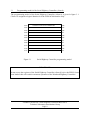
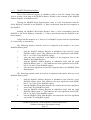
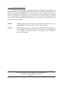
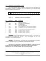
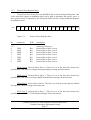
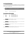
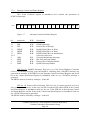
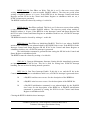
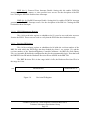
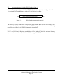
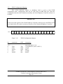
User manual
Notebook
PCMCIA / Serial Highway
Controller
BLN 98-15 UM
February 2001
Eindhoven University of Technology
Department of Physics
Physical & Technical Laboratory Automation Group
Author:
Version:
Date:
R. Smeets
2.0
20-02-2001
Hardware design:
F.C. van Nijmweegen, G.A. Harkema
Table of contents
page
1.
Introduction . . . . . . . . . . . . . . . . . . . . . . . . . . . . . . . . . . . . . . . . . . . . . . . . . . . . . . . . 3
2.
Block diagram of the Notebook/Highway Controller . . . . . . . . . . . . . . . . . . . . . . . . 5
3.
Programming model of the Notebook/Highway Controller . . . . . . . . . . . . . . . . . . . 7
3.1
Programming model of the Serial Highway Controller (client 0) . . . . . . . . 8
3.1.1
Control and Status Register . . . . . . . . . . . . . . . . . . . . . . . . . . . . . . 9
3.1.2
PhyBUS Address Register . . . . . . . . . . . . . . . . . . . . . . . . . . . . . . 12
3.1.3
PhyBUS Word Data Register . . . . . . . . . . . . . . . . . . . . . . . . . . . 13
3.1.4
Interrupt Enquiry Register . . . . . . . . . . . . . . . . . . . . . . . . . . . . . . 14
3.1.5
Maintenance Control and Status Register . . . . . . . . . . . . . . . . . . 15
3.1.6
Maintenance Word Data Register . . . . . . . . . . . . . . . . . . . . . . . . 16
3.1.7
Protocol Error Register Slave . . . . . . . . . . . . . . . . . . . . . . . . . . . 17
3.1.8
Protocol Error Register Master . . . . . . . . . . . . . . . . . . . . . . . . . . 19
3.1.9
Interrupt Control and Status Register . . . . . . . . . . . . . . . . . . . . . 20
3.1.10 EPLD Maintenance Register . . . . . . . . . . . . . . . . . . . . . . . . . . . . 22
3.1.11 Revision ID Register . . . . . . . . . . . . . . . . . . . . . . . . . . . . . . . . . . 22
3.2
Programming model of the EPLD Loader (client 1 ) . . . . . . . . . . . . . . . . 23
3.2.1
EPLD Configuration Register . . . . . . . . . . . . . . . . . . . . . . . . . . . 24
4.
Description of the maintenance modes . . . . . . . . . . . . . . . . . . . . . . . . . . . . . . . . . .
4.1
Maintenance mode 0 . . . . . . . . . . . . . . . . . . . . . . . . . . . . . . . . . . . . . . . . .
4.2
Maintenance mode 1 . . . . . . . . . . . . . . . . . . . . . . . . . . . . . . . . . . . . . . . . .
4.3
Maintenance mode 2 . . . . . . . . . . . . . . . . . . . . . . . . . . . . . . . . . . . . . . . . .
27
27
27
28
Appendix A.
PCMCIA-related documentation . . . . . . . . . . . . . . . . . . . . . . . . . . . . . . . . 29
Appendix B.
EPLD loading (Altera, Application Note AN 87) . . . . . . . . . . . . . . . . . . . 31
TUeDACS PCMCIA / Serial Highway Controller BLN 98-15
Technical Laboratory Automation Group
Page 1
TUeDACS PCMCIA / Serial Highway Controller BLN 98-15
Technical Laboratory Automation Group
Page 2
1.
Introduction
The Notebook/Highway Controller (NHC, BLN 98-15) interfaces any laptop or
notebook computer with an industry standard PCMCIA slot to the PhyBUS Serial Highway
data bus. The PhyBUS Serial Highway data bus can be connected to a TUeDACS/1 module,
or to a TUeDACS/3/6 system crate by means of a Serial Highway PhyBUS controller (SHP,
BLN 98-17) located in this system crate. A TUeDACS/3/6 system crate can host any number
of application-specific and experiment-specific data-acquisition and control interfaces.
The main features of the Notebook/Highway Controller are:
•
PCMCIA compliant type I interface
•
industry-standard PCMCIA interface chip (PCM16C00)
•
16-bit / 32-bit PhyBUS transfers
•
PhyBUS interrupt support
•
serial highway transmission speed:
UTP:
2.5 Mbyte/s (20 Mbit/s)
Fiber optic:
10 Mbyte/s (80 Mbit/s)
The Notebook/Highway Controller is implemented as a dual-function PCMCIA device and is
PCMCIA compliant. This document will therefore only describe the device-specific registers.
For a description of the PCMCIA-specific registers, as well as PCMCIA-specific
programming aspects, consult the documentation listed in Appendix A.
TUeDACS PCMCIA / Serial Highway Controller BLN 98-15
Technical Laboratory Automation Group
Page 3
TUeDACS PCMCIA / Serial Highway Controller BLN 98-15
Technical Laboratory Automation Group
Page 4
2.
Block diagram of the Notebook/Highway Controller
The block diagram of the Notebook/Highway Controller is given in figure 2.1.
PCMCIA BUS
PCM16C00
FUNCTION 1
EPLD
LOADER
PCMCIA
INTERFACE
SERIAL
HIGHWAY
CONTROLLER
ATTRIBUTE
MEMORY
PHYBUS
SERIAL
HIGHWAY
FUNCTION 0
SERIAL
EEPROM
(CIS)
Figure 2.1
Block diagram of the Notebook/Highway Controller
TUeDACS PCMCIA / Serial Highway Controller BLN 98-15
Technical Laboratory Automation Group
Page 5
TUeDACS PCMCIA / Serial Highway Controller BLN 98-15
Technical Laboratory Automation Group
Page 6
3.
Programming model of the Notebook/Highway Controller
The Notebook/Highway Controller is implemented as a dual-function client device
on the PCMCIA bus. Each client device has its own register set that is mapped into the host
processor’s I/O space. Two client devices are implemented:
!
client 0 implements the Serial Highway Controller. This client interfaces the
notebook computer to the PhyBUS Serial Highway. Client 0 is implemented
with PCM16C00 function 0.
!
client 1 implements the EPLD Loader. This client consists of a single I/O
register to load and configure the programmable logic devices (EPLD’s) on
the NHC. These logic devices must be configured before the Serial
Highway Controller (client 0) can be used! Client 1 is implemented with
PCM16C00 function 1.
Each client device has its own programming model that is implemented as a byteoriented I/O register set, of which only even addresses are used to implement 16-bit word
addressing. The base address of each register set is allocated dynamically by making
appropriate service calls to the Card Services driver (Card Services is a PCMCIA standard
and must provided by the host operating system), or by any other means to obtain the
resources assigned by the host operating system. Note that each client has its own I/O base
address!
Communication between the Serial Highway Controller and the PhyBUS is
implemented as a master/slave protocol, in which the Serial Highway Controller is the master
and the PhyBUS is the slave. This terminology (master = Serial Highway Controller, slave =
PhyBUS) is used throughout the rest of this manual.
TUeDACS PCMCIA / Serial Highway Controller BLN 98-15
Technical Laboratory Automation Group
Page 7
3.1
Programming model of the Serial Highway Controller (client 0)
The programming model of the Serial Highway Controller (client 0) is given in figure 3.1.
Client 0 is assigned to logical function 0 of the PCM16C00 interface chip.
0x00
CONTROL AND STATUS REGISTER
R/W
0x02
PHYBUS ADDRESS REGISTER
R/W
0x04
PHYBUS WORD DATA REGISTER
R/W
0x06
INTERRUPT ENQUIRY REGISTER
RO
0x08
MAINTENANCE CSR
R/W
0x0A
MAINTENANCE WORD DATA REGISTER
R/W
0x0C
PROTOCOL ERROR REGISTER SLAVE
RO
0x0E
PROTOCOL ERROR REGISTER MASTER
RO
0x10
INTERRUPT CONTROL AND STATUS REGISTER
R/W
0x12
EPLD MAINTENANCE REGISTER
R/W
0x14
REVISION ID REGISTER
RO
Figure 3.1
Serial Highway Controller programming model
IMPORTANT:
do not access the registers of the Serial Highway Controller (client 0) before the EPLD’s have
been loaded: this will result in erroneous operation of the Notebook/Highway Controller!
TUeDACS PCMCIA / Serial Highway Controller BLN 98-15
Technical Laboratory Automation Group
Page 8
3.1.1
Control and Status Register
This 16-bit read/write register at subaddress 0x00 controls the general operation of
the Serial Highway Controller.
0x00
PE
PEM
PES
X
X
X
X
X
X
IE
RST
X
PER
BT
MNT
ISP
15
14
13
12
11
10
9
8
7
6
5
4
3
2
1
0
Figure 3.2
Control and Status Register
bit
mnemonic
R/W
description
15
14
13
12..7
6
5
4
3
2
1
0
PE
PEM
PES
IE
RST
PER
BT
MNT
ISP
RO
RO
RO
R/W
WO
WO
R/W
R/W
WO
Protocol Error
Protocol Error Master
Protocol Error Slave
not used, reads as zero
Interrupt Enable
ReSeT
not used, reads as zero
Protocol Error Reset
Block Transfer
MaiNTenance operation select
Init Slave PhyBUS
PE (bit 15): Protocol Error. This read-only bit indicates that a protocol error has
occurred; this bit is the logical OR function of the PEM bit and the PES bit. A protocol error
(either at the master side and/or the slave side) is specified by the contents of the Protocol
Error Registers at subaddresses 0x0c (slave) and 0x0e (master).
The PE bit is cleared when setting the RST bit, when setting the PER bit, or when
issuing a software PhyBUS initialisation command by setting the ISP bit.
PEM (bit 14): Protocol Error Master. This read-only bit indicates that a protocol
error has occurred at the master side of the PhyBUS Serial Highway. The protocol error is
specified by the contents of the Protocol Error Register Master at subaddress 0x0e.
The PEM bit is cleared when setting the RST bit, when setting the PER bit, or when
issuing a software PhyBUS initialisation command by setting the ISP bit.
TUeDACS PCMCIA / Serial Highway Controller BLN 98-15
Technical Laboratory Automation Group
Page 9
PES (bit 13): Protocol Error Slave. This read-only bit indicates that a protocol error
has occurred at the slave side of the PhyBUS Serial Highway. The protocol error is specified
by the contents of the Protocol Error Register Slave at subaddress 0x0c.
The PES bit is cleared when setting the RST bit, when setting the PER bit, or when
issuing a software PhyBUS initialisation command by setting the ISP bit.
IE (bit 6): Interrupt Enable. If this bit is set, a PCMCIA interrupt is generated when
one or more of the following conditions occur (see also the description of the Interrupt
Control and Status Register in section 3.1.9):
"
a PhyBUS interface generates an interrupt, and the PBIE bit in the Interrupt
Control and Status Register at subaddress 0x10 is set,
"
a master or slave protocol error has occurred (i.e. the PE bit in the Control
and Status register is set), and the PEIE bit in the Interrupt Control and
Status Register at subaddress 0x10 is set,
"
a PhyBUS read bus error or write bus error has occurred and the BEIE bit in
the Interrupt Control and Status Register at subaddress 0x10 is set,
"
a maintenance interrupt is generated when setting the GMI bit in the
Control and Status Register.
If the IE bit is cleared, no PCMCIA interrupt can be generated. The IE bit is cleared
when setting the RST bit.
RST (bit 5): ReSeT. Setting this bit initialises the Serial Highway Controller. Setting
the RST bit does NOT reset the PhyBUS connected to the Serial Highway, nor does it reset
the EPLD Loader (client 1), nor does it clear the contents of the EPLD’s!
Setting the RST bit is a one-time command. This bit need not be cleared.
PER (bit 3): Protocol Error Reset. Setting this bit clears the PE bit, the PEM bit and
the PES bit.
Setting the PER bit is a one-time command. This bit need not be cleared.
TUeDACS PCMCIA / Serial Highway Controller BLN 98-15
Technical Laboratory Automation Group
Page 10
BT (bit 2): Block Transfer. Setting this bit selects block transfer for reading data
from or writing data to a PhyBUS interface located in the PhyBUS slave crate. If block
transfer is selected (BT bit is set), only the first read or write transfer uses the PhyBUS
Address Register at subaddress 0x01 to select a PhyBUS interface address in the PhyBUS
crate. All subsequent read and write transfers use this same PhyBUS address, as long as the
BT bit is set. This mechanism is used to perform efficient block transfers to or from a
PhyBUS interface with auto-increment data registers.
MNT (bit 1): Maintenance operation select. Setting this bit enables the Serial
Highway Controller for maintenance operation. A specific maintenance mode is selected
with the MM2, MM1, and MM0 bits in the Maintenance Control and Status Register at
subaddress 0x08. See section 4 for a description of the maintenance modes.
ISP (bit 0): Init Slave PhyBUS. Setting this bit generates a global PhyBUS
initialisation signal in the PhyBUS slave crate. If this initialisation signal is not acknowledged
by the PhyBUS slave crate, the BERI bit in the Interrupt Control and Status Register at
subaddress 0x10 is set.
Setting the ISP bit is a one-time command. This bit need not be cleared.
TUeDACS PCMCIA / Serial Highway Controller BLN 98-15
Technical Laboratory Automation Group
Page 11
3.1.2
PhyBUS Address Register
This 16-bit read/write register at subaddress 0x02 must be initialized with the
PhyBUS address of an interface in the PhyBUS crate. After the address is written to this
register, data can be read from or written to the corresponding PhyBUS address by reading or
writing the PhyBUS Word Data Register at subaddress 0x02 (16-bit data transfer).
0x02
X
X
X
X
15
14
13
12
Figure 3.3
PA11 PA10
11
10
PA9
PA8
PA7
PA6
PA5
PA4
PA3
PA2
PA1
PA0
9
8
7
6
5
4
3
2
1
0
PhyBUS Address Register
As PhyBUS addresses are in the range 0..4095, only bits 0..11 in this register are
used. Bits 12..15 are not used and always read as zero, writing these bits has no effect.
If block transfer is required, application software must use the following sequence:
1.
2.
3.
set the BT bit in the Control and Status Register at subaddress 0x00,
initialize the PhyBUS Address Register with the required address of an
interface in the slave crate,
execute the required number of read and/or write accesses by reading or
writing the PhyBUS Word Data Register (subaddress 0x04).
TUeDACS PCMCIA / Serial Highway Controller BLN 98-15
Technical Laboratory Automation Group
Page 12
3.1.3
PhyBUS Word Data Register
This 16-bit read/write register at subaddress 0x04 is used for reading 16-bit data
from or writing 16-bit data to the PhyBUS address defined by the contents of the PhyBUS
Address Register at subaddress 0x02.
Writing the PhyBUS Word Data Register starts a 16-bit write-transfer from the
Serial Highway Controller to the PhyBUS, i.e. data is transferred from the host computer to
the PhyBUS.
Reading the PhyBUS Word Data Register starts a 16-bit read-transfer from the
PhyBUS to the Serial Highway Controller, i.e. data is transferred from the PhyBUS to the
host computer.
Longword data transfers to or from a 32-bit PhyBUS register must be implemented
as 2 consecutive word transfers.
The following sequence must be used for a longword write transfer to an (even)
PhyBUS address pbad:
1.
2.
3.
4.
load the PhyBUS Address Register at subaddress 0x02 with the (even)
PhyBUS address pbad. This addresses the most significant word (MSW,
bits 31..16) of the 32-bit PhyBUS register.
write the most significant word (MSW) of the longword data to the
PhyBUS Word Data Register.
load the PhyBUS Address Register at subaddress 0x02 with the (odd)
PhyBUS address pbad + 1. This addresses the least significant word (LSW,
bits 15..0) of the 32-bit PhyBUS register.
write the least significant word of the longword data to the PhyBUS Word
Data Register.
The following sequence must be used for a longword read transfer from an (even)
PhyBUS address pbad:
1.
2.
3.
4.
load the PhyBUS Address Register at subaddress 0x02 with the (even)
PhyBUS address pbad. This addresses the most significant word (MSW,
bits 31..16) of the 32-bit PhyBUS register.
read the PhyBUS Word Data Register, this returns the the most significant
word of the 32-bit PhyBUS register
load the PhyBUS Address Register at subaddress 0x02 with the (odd)
PhyBUS address pbad + 1.This addresses the least significant word (LSW,
bits 15..0) of the 32-bit PhyBUS register.
read the PhyBUS Word Data Register, this returns the the least significant
word of the 32-bit PhyBUS register
TUeDACS PCMCIA / Serial Highway Controller BLN 98-15
Technical Laboratory Automation Group
Page 13
3.1.4
Interrupt Enquiry Register
This 16-bit read-only Interrupt Enquiry Register at subaddress 0x06 identifies the
PhyBUS interface(s) in the PhyBUS that has/have generated an interrupt. Each bit in this
register corresponds to a PhyBUS data line associated with a specific PhyBUS interface. If a
bit in the Interrupt Enquiry Register is set, an interrupt has been generated by a PhyBUS
interface of which the corresponding interrupt bit has been selected, and whose interrupt has
been enabled. If a bit in the Interrupt Enquiry Register is cleared, the corresponding interface
has not generated an interrupt.
NOTE 1:
reading the Interrupt Enquiry Register generates an Interrupt Enquiry Cycle
on the PhyBUS, thereby removing the cause of the interrupt.
NOTE 2:
reading the Interrupt Enquiry Register automatically clears this register for
the next PhyBUS interrupt cycle! In order to handle all interrupts properly,
it is necessary to copy the contents of this register into a variable or
processor data register.
TUeDACS PCMCIA / Serial Highway Controller BLN 98-15
Technical Laboratory Automation Group
Page 14
3.1.5
Maintenance Control and Status Register
This 16-bit read/write register at subaddress 0x08 is used to test and diagnose the
Serial Highway Controller in maintenance mode, i.e. the MNT bit in the Control and Status
Register at subaddress 0x00 must be set.
0x08
X
X
X
X
X
X
X
ITM
INM
X
15
14
13
12
11
10
9
8
7
6
RST TPES TIRQ MM2 MM1 MM0
5
4
3
2
Figure 3.4
Maintenance Control and Status Register
bit
mnemonic
R/W
description
15..9
8
7
6
5
4
3
2
1
0
ITM
INM
RST
TPES
TIRQ
MM2
MM1
MM0
RO
RO
WO
WO
WO
R/W
R/W
R/W
not used, read as zero
InterrupT enquiry Maintenance
INit Maintenance
not used, reads as zero
ReSeT Maintenance Control and Status Register
Test Protocol Error Slave (maintenance mode 2)
Test Interrupt ReQuest (maintenance mode 2)
Maintenance Mode select, bit 2
Maintenance Mode select, bit 1
Maintenance Mode select, bit 0
1
0
ITM (bit 8): InterrupT enquiry Maintenance (maintenance mode 2). See section 4 for
a description of this read-only bit. This bit is cleared by setting the RST bit in the
Maintenance Control and Status Register.
INM (bit 7): INit Maintenance. See section 4 for a description of this bit. This bit is
cleared by setting the RST bit in the Maintenance Control and Status Register.
RST (bit 5): ReSeT Maintenance Control and Status Register. Setting this write-only
bit clears the ITM bit and the INM bit in the Maintenance Control and Status Register.
Setting the RST bit is a one-time command. This bit need not be cleared.
TUeDACS PCMCIA / Serial Highway Controller BLN 98-15
Technical Laboratory Automation Group
Page 15
TPES (bit 4): Test Protocol Error Slave (maintenance mode 2). Setting this bit sets
the PES bit (and thus the PE bit) in the Control and Status Register at subaddress 0x00, if
maintenance mode 2 is selected. See section 4.
Setting the TPES bit is a one-time command. This bit need not be cleared.
TIRQ (bit 3): Test Interrupt ReQuest (maintenance mode 2). Setting this bit
generates a PhyBUS interrupt if maintenance mode 2 is selected. See section 4.
Setting the TIRQ bit is a one-time command. This bit need not be cleared.
MM2..MM0 (bits 2..0): Maintenance Mode select bits 2..0. These bits select a
maintenance mode for the serial Highway Controller. Maintenance modes 0..2 are available.
Selecting a maintenance mode in the range 3..7 results in undefined operation. See section 4
for a description of the maintenance modes.
3.1.6
Maintenance Word Data Register
This 16-bit read/write register at subaddress 0x0a is used in maintenance mode 1.
See section 4 for a description of this maintenance mode.
TUeDACS PCMCIA / Serial Highway Controller BLN 98-15
Technical Laboratory Automation Group
Page 16
3.1.7
Protocol Error Register Slave
If a protocol error at the slave side (PhyBUS) has occurred during transmission, this
16-bit read-only register at subaddress 0x0c can be used to determine the specific error. A
slave protocol error is indicated by the PE and the PES bit in the Control and Status Register
at subaddress 0x00.
0x0C
X
X
X
X
X
X
X
X
X
15
14
13
12
11
10
9
8
7
PES6 PES5 PES4 PES3 PES2 PES1 PES0
6
5
Figure 3.5
Protocol Error Register Slave
bit
mnemonic
R/W
description
15..7
6
5
4
3
2
1
0
PES6
PES5
PES4
PES3
PES2
PES1
PES0
RO
RO
RO
RO
RO
RO
RO
not used, read as zero
Protocol Error Slave, error 6
Protocol Error Slave, error 5
Protocol Error Slave, error 4
Protocol Error Slave, error 3
Protocol Error Slave, error 2
Protocol Error Slave, error 1
Protocol Error Slave, error 0
4
3
2
1
0
PES6 (bit 6): Protocol Error Slave 6. This bit is set if the slave has detected an
invalid check code when receiving an Interrupt Enquiry message from the master.
PES5 (bit 5): Protocol Error Slave 5. This bit is set if the slave has detected an
invalid check code when receiving a PhyBUS Initialization message from the master.
PES4 (bit 4): Protocol Error Slave 4. This bit is set if the slave has detected a Read
message and a Write message at the same time.
PES3 (bit 3): Protocol Error Slave 3. This bit is set if the slave has detected an
invalid number of SYNC-CLOCK pulses during a block read transfer.
TUeDACS PCMCIA / Serial Highway Controller BLN 98-15
Technical Laboratory Automation Group
Page 17
PES2 (bit 2): Protocol Error Slave 2. This bit is set if the slave has detected an
invalid number of SYNC-CLOCK pulses during a normal (i.e. non-block) read transfer.
PES1 (bit 1): Protocol Error Slave 1. This bit is set if the slave has detected an
invalid number of SYNC-CLOCK pulses during a block write transfer.
PES0 (bit 0): Protocol Error Slave 0. This bit is set if the slave has detected an
invalid number of SYNC-CLOCK pulses during a normal (i.e. non-block) write transfer.
TUeDACS PCMCIA / Serial Highway Controller BLN 98-15
Technical Laboratory Automation Group
Page 18
3.1.8
Protocol Error Register Master
If a protocol error at the master side (Serial Highway Controller) has occurred during
transmission, this 16-bit read-only register at subaddress 0x0e can be used to determine the
specific error. A slave protocol error is indicated by the PE and the PEM bit in the Control
and Status Register at subaddress 0x00.
0x0E
X
X
X
X
X
X
X
X
X
X
X
X
15
14
13
12
11
10
9
8
7
6
5
4
Figure 3.6
Protocol Error Register Master
bit
mnemonic
R/W
description
15..4
3
2
1
0
PEM3
PEM2
PEM1
PEM0
RO
RO
RO
RO
not used, read as zero
Protocol Error Master, error 3
Protocol Error Master, error 2
Protocol Error Master, error 1
Protocol Error Master, error 0
PEM3 PEM2 PEM1 PEM0
3
2
1
0
PEM3 (bit 3): Protocol Error Master 3. This bit is set if an error occurs during a read
transfer. The number of ACK-CLOCK pulses exceeds 20.
PEM2 (bit 2): Protocol Error Master 2. This bit is set if an error occurs during a
write transfer. The number of ACK-CLOCK pulses exceeds 8.
PEM1 (bit 1): Protocol Error Master 1. This bit is set if an invalid check code is
detected during a write transfer.
PEM0 (bit 0): Protocol Error Master 0. This bit is set if an invalid check code is
detected when receiving an Interrupt Request message from the slave.
TUeDACS PCMCIA / Serial Highway Controller BLN 98-15
Technical Laboratory Automation Group
Page 19
3.1.9
Interrupt Control and Status Register
This 16-bit read/write register at subaddress 0x10 controls the generation of
PCMCIA interrupts.
0x10
PBI
PEI BERW BERR BERI
X
X
X
X
X
X
X
GMI
15
14
10
9
8
7
6
5
4
3
13
12
11
Figure 3.7
Interrupt Control and Status Register
bit
mnemonic
R/W
description
15
14
13
12
11
10..4
3
2
1
0
PBI
PEI
BERW
BERR
BERI
GMI
BEIE
PEIE
PBIE
R/W
R/W
R/W
R/W
R/W
WO
R/W
R/W
R/W
PhyBUS Interrupt
Protocol Error Interrupt
PhyBUS Bus ERror on Write
PhyBUS Bus ERror on Read
PhyBUS Bus ERror on Initialisation
not used, read as zero
Generate Maintenance Interrupt
Bus Error Interrupt Enable
Protocol Error Interrupt Enable
PhyBUS Interrupt Enable
BEIE PEIE PBIE
2
1
0
PBI (bit 15): PhyBUS Interrupt. This bit is set if the Serial Highway Controller
receives an interrupt message from the PhyBUS, indicating that a PhyBUS interface has
generated an interrupt. If the PBIE bit in the Interrupt Control and Status Register and the IE
bit in the Control and Status Register at subaddress 0x00 are set, a PCMCIA interrupt is
generated.
The PBI bit must be cleared by writing a 1 to this bit.
PEI (bit 14): Protocol Error Interrupt. This bit is set if a master protocol error or a
slave protocol error occurs. In this case, the PE bit and the PES and/or PEM in the Control
and Status Register at subaddress 0x00 are also set. If the PEIE bit in the Interrupt Control
and Status Register and the IE bit in the Control and Status Register at subaddress 0x00 are
set, a PCMCIA interrupt is generated.
The PEI bit must be cleared by writing a 1 to this bit.
TUeDACS PCMCIA / Serial Highway Controller BLN 98-15
Technical Laboratory Automation Group
Page 20
BERW (bit 13): Bus ERror on Write. This bit is set if a bus error occurs when
writing to a non-existent or non-accessable PhyBUS address. The time-out period when
writing a PhyBUS address is 10 µsec. If the BEIE bit in the Interrupt Control and Status
Register and the IE bit in the Control and Status Register at subaddress 0x00 are set, a
PCMCIA interrupt is generated.
The BERW bit must be cleared by writing a 1 to this bit.
BERR (bit 12): Bus ERror on Read. This bit is set if a bus error occurs when reading
a non-existent or non-accessable PhyBUS address. The time-out period when reading a
PhyBUS address is 10 µsec. If the BEIE bit in the Interrupt Control and Status Register and
the IE bit in the Control and Status Register at subaddress 0x00 are set, a PCMCIA interrupt
is generated.
The BERR bit must be cleared by writing a 1 to this bit.
BERI (bit 11): Bus ERror on Initialising PhyBUS. This bit is set when a PhyBUS
initialisation command is not acknowledged by the PhyBUS slave crate. If the BEIE bit in the
Interrupt Control and Status Register and the IE bit in the Control and Status Register at
subaddress 0x00 are set, a PCMCIA interrupt is generated.
The initialisation command is generated when setting the ISP bit in the Control and
Status Register at subaddress 0x00.
The BERI bit must be cleared by writing a 1 to this bit.
GMI (bit 3): Generate Maintenance Interrupt. Setting this bit immediately generates
an interrupt on the PCMCIA bus. This bit is used for testing bare PCMCIA interrupt
handling. Do not use this bit during normal operation.
BEIE (bit 2): Bus Error Interrupt Enable. If this bit is set, and the IE bit in the
Control and Status Register at subaddress 0x00 is set, a PCMCIA interrupt is generated when:
!
a PhyBUS read bus error occurs. See the description of the BERR bit.
!
a PhyBUS write bus error occurs. See the description of the BERW bit.
!
a PhyBUS initialisation command is not acknowledged by the PhyBUS
slave crate. See the description of the BERI bit. A PhyBUS initialisation
command is generated by setting the ISP bit in the Control and Status
Register at subaddress 0x00.
Clearing the BEIE bit disables these interrupts.
TUeDACS PCMCIA / Serial Highway Controller BLN 98-15
Technical Laboratory Automation Group
Page 21
PEIE (bit 1): Protocol Error Interrupt Enable. Setting this bit enables PCMCIA
interrupt generation if a master- or slave protocol error occurs. See the decription of the PEI
bit. Clearing the PEIE bit disables these interrupts.
PBIE (bit 0): PhyBUS Interrupt Enable. Setting this bit enables PCMCIA interrupt
generation if a PhyBUS interrupt occurs. See the decription of the PBI bit. Clearing the PBI
bit disables these interrupts.
3.1.10
EPLD Maintenance Register
This 16-bit read/write register at subaddress 0x12 is used to test read/write accesses
from/to the EPLD. These tests are used to verify that the EPLD has been loaded correctly.
3.1.11
Revision ID Register
This 16-bit read-only register at subaddress 0x14 holds the revision number of the
RBF file with which the EPLD logic has been loaded (by client 1, see section 3.2), and the
revision number of the Notebook/Highway Controller hardware. An RBF file (Raw Binary
File, see Appendix B) holds the configuration data for the programmable logic. Note that both
the RBF Revision ID and the Hardware Revision ID are defined in the RBF file!
The RBF Revision ID is in the range 0x001..0xffe, the Hardware Revision ID is in
the range 0x1..0xe.
0x14
RBF REVISION ID
15
14
13
12
Figure 3.8
11
10
9
HARDWARE REV. ID
8
7
6
5
4
3
Revision ID Register
TUeDACS PCMCIA / Serial Highway Controller BLN 98-15
Technical Laboratory Automation Group
Page 22
2
1
0
3.2
Programming model of the EPLD Loader (client 1 )
The programming model for the EPLD Loader (client 1) is given in figure 3.9. Client
1 is assigned to logical function 1 of the PCM16C00 interface chip.
0x00
Figure 3.9
EPLD CONFIGURATION REGISTER
R/W
EPLD Loader programming model
The EPLD’s must be loaded with configuration data from an RBF disk file (Raw Binary File,
see Appendix B). The loading program for the EPLD configuration data must meet the timing
constraints as defined by the timing diagrams in Appendix B.
NOTE: the Pin Polarity Register at subaddress 0x03e4 in the PCM16C00 Attribute Memory
Space must be set to the value 0x01 to enable loading of the EPLD.
TUeDACS PCMCIA / Serial Highway Controller BLN 98-15
Technical Laboratory Automation Group
Page 23
3.2.1
EPLD Configuration Register
This 16-bit read/write register at subaddress 0x00 is used to load EPLD
configuration data. Configuration data can be read from an RBF disk file. After the
configuration data has been loaded successfully, the Serial Highway Controller (client 0) is
available.
IMPORTANT:
do not access the registers of the Serial Highway Controller (client 0) before the EPLD’s have
been loaded: this will result in erroneous operation of the Notebook/Highway Controller!
0x00
X
X
X
X
X
X
X
X
X
X
X
CLR
15
14
13
12
11
10
9
8
7
6
5
4
Figure 3.10
EPLD Configuration Register
bit
mnemonic
R/W
description
15..5
4
3
2
1
0
CLR
CLK
DATA
STA
DONE
WO
R/W
R/W
RO
RO
not used, reads as zero
CLeaR EPLD’s (active LOW !!)
CLocK
DATA
STAtus
DONE
CLK DATA STA DONE
3
TUeDACS PCMCIA / Serial Highway Controller BLN 98-15
Technical Laboratory Automation Group
Page 24
2
1
0
CLR (bit 4): CLeaR EPLD’s (active LOW!!). Clearing this bit clears the
configuration data of the EPLD’s, after which the EPLD’s can be (re)loaded. The CLR bit
must be set to enable EPLD (re)loading. Note that the CLR bit is an active LOW bit: if the bit
is cleared, EPLD’s are cleared and (re)loading is inhibited!
NOTE: on earlier (prototype) versions of the BLN 98-15, the CLR bit is a read/write bit.
CLK (bit 3): setting this bit clocks the data contained in the DATA bit (bit 2) from
the EPLD Configuration Register, into the EPLD’s. Data contained in the DATA bit is part of
the EPLD configuration data file.
In order to clock the next data bit, the CLK bit must be cleared first.
DATA (bit 2): DATA. This bit contains a the configuration data bit for the EPLD’s.
The data from this bit is loaded into the EPLD’s upon setting the CLK bit. Data for the
DATA bit must be read from an EPLD configuration file (RBF file).
STAtus (bit 1): STAtus. If this bit is set, the EPLD’s are ready to accept (new)
configuration data to be loaded using the CLK and DATA bit. If this bit is cleared, the
EPLD’s are not ready to accept configuration data.
DONE (bit 0): DONE. If this bit is set, the EPLD’s have been configured
successfully (configuration is done). This bit is cleared after power-up or when clearing the
CLR bit.
TUeDACS PCMCIA / Serial Highway Controller BLN 98-15
Technical Laboratory Automation Group
Page 25
TUeDACS PCMCIA / Serial Highway Controller BLN 98-15
Technical Laboratory Automation Group
Page 26
4.
Description of the maintenance modes
The Serial Highway Controller can be tested and diagnosed by using maintenance
modes. Maintenance operation for the Serial Highway Controller is enabled by setting the
MNT bit (bit 1) in the Control and Status Register at subaddress 0x00. A specific
maintenance mode is selected with the MM2..MM0 bits in the Maintenance Control and
Status Register at subaddress 0x08.
4.1
Maintenance mode 0
Maintenance mode 0 is used to execute read/write tests on the following registers:
4.2
"
PhyBUS Address Register, subaddress 0x02
"
PhyBUS Word Data Register, subaddress 0x04
Maintenance mode 1
Maintenance mode 1 is used to test data and control lines from the master to an
(internal) maintenance slave register. An external loopback connector is required for this
maintenance mode. Read/write tests can be executed on the following registers:
"
PhyBUS Address Register, subaddress 0x02.
"
Maintenance Word Data Register, subaddress 0x0a
The minimum delay time between writing one of these registers and reading the
same register to obtain the data previously written, is defined by the tranmission protocol, and
is approximately 5 µs (depends on the transfer).
TUeDACS PCMCIA / Serial Highway Controller BLN 98-15
Technical Laboratory Automation Group
Page 27
4.3
Maintenance mode 2
Maintenance mode 2 is used to test data and control lines from a simulated slave to
the master. An external loopback connector is required for this maintenance mode. The
following tests can be executed:
"
simulate a slave interrupt. This is tested by setting the TIRQ bit in the
Maintenance Control and Status Register at subaddress 0x08. If the IE bit in
the Control and Status Register at subaddress 0x00 has been set, a PhyBUS
interrupt is generated. The delay time between setting the TIRQ bit and the
interrupt being generated, is defined by the transmission protocol, and is
approximately 1 µs.
The contents of the Interrupt Enquiry Register at subaddress 0x06
is undefined!
"
simulate a slave protocol error. This is tested by setting the TPES bit in the
Maintenance Control and Status Register at subaddress 0x08. Setting this
bit sets the PES and the PE bit in the Control and Status Register at
subaddress 0x00. The delay time between setting the TPES bit and the PES
and PE bits being set, is defined by the transmission protocol, and is
approximately 1 µs.
Additional testing can be performed by writing data in the range
0..127 to the PhyBUS Word Data Register at subaddress 0x04. When the
PES and PE bit are set, the Protocol Error Register Slave at subaddress 0x0c
should hold the the data written to the PhyBUS Word Data Register.
TUeDACS PCMCIA / Serial Highway Controller BLN 98-15
Technical Laboratory Automation Group
Page 28
Appendix A.
PCMCIA-related documentation
1.
PCM16C00 Configurable Multi Function PCMCIA Interface Chip
National Semiconductor datasheet
October 1994
2.
Ontwerpspecificaties PCMCIA/Seriële PhyDAS Highway Controller, concept, versie
2
Interne documentatie BLN
G. Harkema
12 februari 1999
3.
Additionele Ontwerpspecificaties Notebook/Highway Controller
Interne documentatie BLN
G. Harkema
9 augustus 1999
4.
PC Card Standard, Volume 5: Card Services Specification
PCMCIA/JEIDA
March 1997
5.
The PCMCIA Developer’s Guide, second edition
Michael T. Mori and W. Dean Welder
Sycard Technology
1994-1995
6.
PCMCIA System Architecture
16-bit PC Cards, second edition
Don Anderson
Mindshare, Inc.
1995
7.
PCCproto 200 Documentation Package
Sycard Technology
TUeDACS PCMCIA / Serial Highway Controller BLN 98-15
Technical Laboratory Automation Group
Page 29
TUeDACS PCMCIA / Serial Highway Controller BLN 98-15
Technical Laboratory Automation Group
Page 30
Appendix B.
EPLD loading (Altera, Application Note AN 87)
See following pages
TUeDACS PCMCIA / Serial Highway Controller BLN 98-15
Technical Laboratory Automation Group
Page 31
TUeDACS PCMCIA / Serial Highway Controller BLN 98-15
Technical Laboratory Automation Group
Page 32