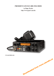
Download Service Manual Stryker SR
Transcript
SR-955HP alignment
Downloaded from www.cbradio.nl
。
。
。
。
。。
。
。
。
。
。
。
。
。
。
。
。
。
。。
。
。
。
。
。
。
。
。
。
。
。
。
。
。
。
。。
。
。
。。
。。
。。
。
。
。。
。。
。
。
。。
。
。
。。
。
。
。。
。
。。
。
。
。
。。
。。。
。
。。。
。
。。。
。
。
。。。
。
。。。
。
。
。。。。。
。
Note before testing:
Testing Voltage 13.8V
Pay attention to have correct setup for testing machine.
Do not change inside or parameter at will.
Before assemble the cover, delete the factory mode by the factory software.
Do remember to reset radio to factory default after assemble the radio.
。
。
。
。
。。
。
。
。
。
。
。
。
。
。
。
。
。
。。
。
。
。
。
。
。
。
。
。
。
。
。
。
。
。
。。
。
。
。。
。。
。。
。
。
。。
。。
。
。
。。
。
。
。。
。
。
。。
。
。。
。
。
。
。。
。。。
。
。。。
。
。。。
。
。
。。。
。
。。。
。
。
。。。。。
。
Frequency point for testing:
Band A
Channel 1:RX(24.025) 、TX(24.105)、NB/ANL open
Channel 2:RX(27.065) 、TX(27.100) 、NB/ANL open
Channel 3:RX(30.105) 、TX(30.095) 、NB/ANL open
。
。
。
。
。。
。
。
。
。
。
。
。
。
。
。
。
。
。。
。
。
。
。
。
。
。
。
。
。
。
。
。
。
。
。。
。
。
。。
。。
。。
。
。
。。
。。
。
。
。。
。
。
。。
。
。
。。
。
。。
。
。
。
。。
。。。
。
。。。
。
。。。。
。。
。。
。。
。。
。
。。。。。。
。
VCO testing
。
。
。
。
。。
。
。
。
。
。
。
。
。
。
。
。
。
。。
。
。
。
。
。
。
。
。
。
。
。
。
。
。
。
。。
。
。
。。
。。
。。
。
。
。。
。。
。
。
。。
。
。
。。
。
。
。。
。
。。
。
。
。
。。
。。。
。
。。。
。
。。。
。
。
。。。
。
。。。
。
。
。。。。。
。
New radio reset:All new radio will auto reset after power on, but required to manual reset again: Hold FUNC+SCAC+
COLOR key and power on the radio,LCD show “REST ALL” then show ”REST END” , the full reset is done.
Note:Hold FUNC to power is half reset, the LCD show RESET.
Check Quiescent Current Turn off SQ,In AM/FM/USB/LSB, all < 400mA(LCD color is RGB)
Check Display: Hold SCAN to power on,to check 2 LCD.
Check Backlight LED:
A、Power on and repeat press COLOR key,the LED show :RED、GREEN、BLUE 3 colors,make sure the LED work fine
before install LCD board.
B、Switch to DIM position ,The big LCD show DIM:31,adjust channel knob until big LCD show DIM:OFF,check the changes
of darkles, the smaller data get darker backlight.
Check voltage: In function menu, the “LCD:xxx” Set to N&DC,the big LCD show voltage. The voltage shall be ±
0.10Vcomapred with the supplied voltage, adjust the R521 560K resistance if not match.
Check keys and buttons: check the function, look and touch of full panel, key, switch, Knobs.
Check programming:
Program the radio with Frequency point listed in top of this instruction, cancel the factory mode by the factory software.
VCO voltage: Testing TP510 and TP509,
TP510:between 1.0-4.0 in all frequency band,no Fluctuation,if not match, adjust C801 8P capacitance,Capacitance
toleration is ±2P,check other problem if it not match.
TP509:between 0.8-5.5 in all frequency band,no Fluctuation,if not match, adjust C555 4P5 capacitance,Capacitance
toleration is ±2P,check other problem if it not match.
Note:2 VCO are connected, when TP510 testing un lock,TP509 also unlock,only when TP510 locked,TP509 can be locked
。
。。
。
。
。
。
。
。
。
。
。
。
。
。
。
。
。
。
。
。
。
。
。
。
。
。
。
。
。
。
。
。
。
。
。
。
。
。
。
。
。
。。。
。
。。。。。。
。。。。
。。。。
。。。。
。。。。
。
。。。。。。
。。。。
。。。。
。。。。
。。。。
。
。。。。。。
。
Frequency adjustment:
Enter testing mode:Hold COLOR to power on,adjust FREQ for rough adjust,CLAR external spindle for fine adjust,FUNC、
COLOR key are used to switch between testing items.
VCO frequency adjustment:Testing point TP513,FM mode,CLAR inner spindle in middle position(an Obviously fixed-point
can be find in middle point)
,before adjustment, power on radio in USB mode for 2-5 minutes.
Choose FRQ 320:adjust L807,frequency 38.695MHZ±10HZ,background noise < 40HZ
Choose F05 XXX:adjust frequency 38.695MHZ±10HZ,background noise < 40HZ
Turn clockwise and anti clockwise to the end and test. the fluctuation need 500±100Hz, switch the knob
to middle position after testing.
Choose F15 XXX: frequency need 38.695MHZ±10HZ,background noise < 40HZ
Turn clockwise and anti clockwise to the end and test. the fluctuation need 1500±200Hz, switch the knob
to middle position after testing.
Choose F25 XXX: frequency need 38.695MHZ±10HZ,background noise < 40HZ
Turn clockwise and anti clockwise to the end and test. the fluctuation need 2500±300Hz, switch the knob
to middle position after testing.
Note:FRQ 320 data can not adjusted,if the frequency fluctuation is <100HZ,you can adjust ±70>
After testing FO5、F15、F25 frequency fluctuation,be sure to turn the CLAR inner spindle in middle position.
BFO frequency adjustment:Enter testing mode,choose BFXX display,testing point TP301
Choose FM mode,frequency need 10.695MHZ±10HZ,background noise < 40HZ
Choose USB mode,frequency need 10.6975MHZ±10HZ,background noise < 40HZ
Choose LSB mode,frequency need 10.6925MHZ±10HZ,background noise < 40HZ
AFF frequency adjustment:Enter testing mode,choose AFFXXX display,testing point TP514
Choose FM mode,frequency need 10.240MHZ±40HZ,background noise < 40HZ
Note1:During alignment,choose the minimum deviated frequency, do well adjust and warm up the testing machine.
If the deviation not meet standard, revise the C582 5P capacitance,Capacitance between 1-6P,if still not OK,check
other index.
Note2:The final frequency are composed by BFO and VCO frequency, when the testing transmitting frequency is error, it is
necessary to recheck both frequency. Due to high requirement on accuracy, do adjust this 2 frequency after the
temperature turn normal if any soldering work near the 10.24MHZ, and 10.6975 MHz component. Y800, Y501,
Y500 must grounded, the housing of L807 and Y800 shall be touched. After finish above alignment, be sure to
install the shield over the 2 VCO to ensure rest alignment
。
。
。
。
。
。
。
。
。
。
。
。
。
。
。
。
。
。
。
。
。
。
。
。
。
。
。
。
。
。
。
。
。
。
。
。
。
。
。
。
。
。
。。。
。
。。。。。。
。。。。
。。。。
。。。。
。。。。
。
。。。。。。
。。。。
。。。。
。。。。
。。。。
。
。。。。。。
。
TX testing
。
。
。
。
。
。
。
。
。
。
。
。
。
。
。
。
。
。
。
。
。
。
。
。
。
。
。
。
。
。
。
。
。
。
。
。
。
。
。
。
。
。
。。。
。
。。。。。。
。。。。
。。。。
。。。。
。。。。
。
。。。。。。
。。。。
。。。。
。。。。
。。。。
。
。。。。。。
。
Note:Voltage 13.8V,testing machine with filter<20HZ HPF and 15KHZ LPF,DE-EMPHASIS is OFF。Clockwise turning
is for increase power, anti clockwise turning is for reduce low. The power switch only work for AM,FM mode.
If the power is too big, connect a Attenuator with testing machine.
。
。
。
。
。
。
。
。
。
。
。
。
。
。
。
。。
。
。
。
。
。
。
。
。
。
。
。
。
。
。
。
。
。
。
。
。
。
。
。
。
。
。。。
。
。。。。。。
。。。。
。。。。
。。。。
。。。。
。
。。。。。。
。。。。
。。。。
。。。。
。。。。
。
。。。。。。
。
TX Voltage:When the FM power is over 50W 时(current around 9A)
,The voltage is 13V
Switch location: All the 5 Rocker Switch fix in middle position,CLAR inner spindle fix in middle point ,MIC GAIN to
maximum
Power supply voltage: In USB mode,switch the power to maximum, adjust W13, until voltage in T9 is 12V±0.1V
Quiescent current:In USB mode ,switch the power to maximum,MIC Short-circuited.
A、 J3 with Short-circuit jumper(J4 without)
,hold PTT, adjust W8 until the current is minimum, adjust
W8 anti direction until the current is 100MA over the minimum value.
B、 J4 with Short-circuit jumper(J3 without)
,hold PTT, adjust W9 until the current is minimum, adjust
W9 anti direction until the current is 100MA over the minimum value.
C、 J3, J4 all without Short-circuit jumper,hold PTT, adjust W7 until the current is minimum, adjust W7
anti direction until the current is 100MA over the minimum value.
D、 Testing the transistor follow above order.
E、 4 transistors must be installed under same voltage
Coil adjustment:Before adjust power,L20、L16 move to corresponding position as the sample,install J3、J4 jumper
Transmit intermediate-frequency transformer adjustment: Choose channel3, FM mode,output power to maximum,adjust
T13、T14,to get maximum output power
Note:After finish above alignment, be sure to install the shield over the T13、T14 to ensure rest alignment.
。
。
。
。
。
。
。
。
。
。
。
。
。
。
。
。
。
。
。
。
。
。
。
。
。
。
。
。
。
。
。
。
。
。
。
。
。
。
。
。
。
。
。。。
。
。。。。。。
。。。。
。。。。
。。。。
。。。。
。
。。。。。。
。。。。
。。。。
。。。。
。。。。
。
。。。。。。
。
FM mode testing:
Coil adjustment:Before adjust power,L20、L16 move to corresponding position as the sample,install J3、J4 jumper
Transmit intermediate-frequency transformer adjustment: Choose channel 3, FM mode,output power to maximum,
adjust T13、T14,to get maximum output power, Note:After finish above alignment, be sure to install
the shield over the T13、T14 to ensure rest alignment.
FM High power:Choose channel 2,adjust output power to maximum, adjust W14 to get power 50W±2W, the power on
channel 1 and channel 3 shall > 40w, current < 10A, frequency 50HZ
FM low power:Choose channel 1、2、3,adjust output power to minimum,the power shall between 0.5-3W,current <2.7A
FM maximum deviation:Choose channel 2,send 2K,30 mV signal to MIC,MIC GAIN adjust to maximum, then adjust W500,
to get frequency deviation between 3.5±0.2KHZ,the deviation on channel 1、3 shall between 3-4.0 KHZ.
FM transmitting background noise:Choose channel 1、2、3,adjust output power to maximum,MIC short-circuited,the
background noise shall < 50HZ
Power RSSI meter:Choose channel 2, 1-2 bar for minimum power, Display 40-60 for 50W
SWR: Choose channel 2, output power to maximum,adjust TC1 to get 2 bar for SWR,reverse adjust to get just one bar
Sensitivity:Choose channel 2,send 1K signal to MIC,adjust machine output , when the frequency deviation is 1.5K,the
audio output of testing machines shall between 5-9mV, SIND >40dB。
。
SNR:Choose channel 2,send 1K signal to MIC,adjust machine output . when the frequency deviation is 1.5k, SNR >40dB
Pre-emphasis:Choose channel 2, send 1K signal to MIC,adjust testing machine output, when frequency deviation is 0.8K,
fix this deviation point as 0 dB point,change modulation and testing:
0.3K:-11~-9 0.5K:-6~-4 1.5K:1~4 2K:3~5 2.50K:2~4 3K:-1~1 4K:-12-~9 5K:-20~-16
FM signaling:Enter test mode,choose CTC/DCS channel ,MIC short circuited,press PTT,adjust frequency knob,adjust
CTC deviation to 0.35K,when testing CTCSS 时,the decode frequency for the testing machine shall be ±0.5Hz
of the radio channel. DCS deviation adjust to 0.45K,with smoothing Waveform symmetry. When testing DCS,
the decode signaling for the resting machine shall be same as the radio channel.
Transmitting RB:Choose channel 2,adjust output power to maximum,send 1KHZ,2S signal,to check if the deviation is
between 2.3-2.5k,frequency 1KHZ±10HZ.
ECHO、MON testing:Choose channel 2,open ECHO function,adjust VOL, DEL, MON to maximum,Hold PTT,you shall hear
your own voice from the speaker,adjust MON,the voice will change,when adjust MON to the let end
MON is off,you will not able to hear your own voice from the speaker.
SWR testing:Choose channel 2,adjust output power to maximum,connect 2 Parallel load of 50R to the antenna connector,
SWR display ±2 bar when it is on 2.
。
。
。
。
。
。
。
。
。
。
。
。
。
。
。
。
。
。
。
。
。
。
。
。
。
。
。
。
。
。
。
。
。
。
。
。
。
。
。
。
。
。。。。
。
。。。。。。
。。。。
。。。。
。。。。
。。。。
。
。。。。。。
。。。。
。。。。
。。。。
。。。。
。
。。。。。。
。
AM mode testing:
Testing machine setup: TUNE MODE set as MANUAL,TUNE
AM DEMOD。
FREQ set on transmitting frequency,AF ANL
IN set on
AM output power:Choose channel 2,adjust to maximum power level, MIC short-circuited, adjust W11 to get power 15W±
0.5W,output power for channel 1 and channel 3 > 12W,current < 5.5A
AM low power:Choose channel 2,adjust to minimum power level, MIC short-circuited, to get power 0.5W-3W,current < 3A
AM High power modulation:Choose channel 2, adjust to maximum power level, input 1.25K 30MV signal to MIC, adjust V10,
the frequency deviation between 95%±5%,on channel 1 and channel 3 frequency deviation between
80-100%,PEP power > 50W,current <5.8A,W501 must in middle position,do not adjust it.
AM transmitting background noise:Choose channel 1、2、3,adjust to maximum power level,MIC short-circuited,the back
ground noise shall be < 1.5%。
Sensitivity:Choose channel2 ,send 1Ksignal to MIC,adjust machine output, when the frequency deviation is on 60%,the
audio output of testing machines shall between 1-3mV, SIND >26dB。
SNR:Choose channel 2,send a1K signal to MIC,adjust testing machine output . when the frequency deviation is on 60%,
SNR >40dB
Pre-emphasis:Choose channel 2,adjust to maximum power, send 1K signal to MIC,adjust testing machine output, when
frequency deviation is on 30%,fix this deviation point as 0 dB point,change modulation and testing:
0.3K:-2~1 0.5K:-2~1 1.5K:-2~1 2K:-2~1 2.50K:-2~1 3K:-6-~1 4K:-18-~13 5K:-26~-20
AM low Power residual amplitude modulation:Choose channel 1、2、3,adjust to minimum power,send 1K 30 mV signal
to MIC,when testing machine on FM,residual amplitude modulation need <1.2KHZ
AM High power residual amplitude modulation:Choose channel 1、2、3,adjust to maximum power,send 1K 30 mV signal
to MIC,when testing machine on FM,residual amplitude modulation need <1.2KHZ
AM amplitude balance: Choose channel 1、2、3,adjust to maximum power Spectrum CENTER frequency set same as testing
machine,band width at 10KHZ,REF LEVEL at 50 dB,send 1.25K,30 mV signal to MIC,Observe the Waveform symmetry,
the Fluctuation shall not over 2 dB。
。
。
。
。
。
。
。
。
。
。
。
。
。
。
。
。
。
。
。
。
。
。
。
。
。
。
。
。
。
。
。
。
。
。
。
。
。
。
。
。
。
。
。。。
。
。。。。。。
。。。。
。。。。
。。。。
。。。。
。
。。。。。。
。。。。
。。。。
。。。。
。。。。
。
。。。。。。
。
PA mode testing:
PA testing:Switch to PA mode,hold PTT,the speaker can not give out sound, connect a 8W 3R speaker to the PA port in the
rear of the radio,adjust VOL,the speaker will work.
。
。
。
。
。
。
。
。
。
。
。
。
。
。
。
。
。
。
。
。
。
。
。
。
。
。
。
。
。
。
。
。
。
。
。
。
。
。
。
。
。
。
。。。
。
。。。。。。
。。。。
。。。。
。。。。
。。。。
。
。。。。。。
。。。。
。。。。
。。。。
。。。。
。
。。。。。。
。
USB mode testing:
Balance adjust:choose channel 2,MIC short circuited,Spectrum CENTER frequency set same as testing channel,band width
at 10KHZ,AVG=5, REF LEVEL at 45 dB. Hold PTT, adjust W502 until the center frequency of the Spectrum reach minimum,
the value shall < -8dBm in USB or LSB mode.
Note:after testing,be sure to assemble the shield for L807.
USB high power and frequency error:Choose channel 2,adjust W6 to get 60W power,check if the frequency for the
modulation signal is 1KHZ±50HZ,check if the power on channel 1 and 3is over 55W,current
<10.5A,and SIND>30dB。
(testing machine condition:MIC with 1K、30 mV signal,TUNE MODE:
MANUAL,TUNE FREQ: with testing frequency,AF ANL IN: SSB)
USB sensitivity:choose channel 2,MIC with 1K,30 m V signal,turn power the 0,adjust MIC input value,to get -3 dB,
the present value input is the sensitivity,the value shall between 0.8-2mV.
。
。
。
。
。
。
。
。
。
。
。
。
。
。
。
。
。
。
。
。
。
。
。
。
。
。
。
。
。
。
。
。
。
。
。
。
。
。
。
。
。
。
。。。
。
。。。。。。
。。。。
。。。。
。。。。
。。。。
。
。。。。。。
。。。。
。。。。
。。。。
。。。。
。
。。。。。。
。
LSB mode testing:
LSB power and frequency error:check if power on channel 1、2、3is over 55W,current <10.5A,SIND>30dB,check if
modulation signal frequency is -1KHZ±50HZ。(testing machine condition:MIC with 1K、30 mV
signal,TUNE MODE: MANUAL,TUNE FREQ: with testing frequency,AF ANL IN: SSB)
LSB sensitivity:choose channel 2,MIC with 1K,30 m V signal,turn power the 0,adjust MIC input value,to get -3 dB,
the present value input is the sensitivity,the value shall between 0.8-2mV.
。
。
。
。
。
。
。
。
。
。
。
。
。
。
。
。
。
。
。
。
。
。
。
。
。
。
。
。
。
。
。
。
。
。
。
。
。
。
。
。
。
。
。。。
。
。。。。。。
。。。。
。。。。
。。。。
。。。。
。
。。。。。。
。。。。
。。。。
。。。。
。。。。
。
。。。。。。
。
RX testing
。
。
。
。
。
。
。
。
。
。
。
。
。
。
。
。
。
。
。
。
。
。
。
。
。
。
。
。
。
。
。
。
。
。
。
。
。
。
。
。
。
。
。。。
。
。。。。。。
。。。。
。。。。
。。。。
。。。。
。
。。。。。。
。。。。
。。。。
。。。。
。。。。
。
。。。。。。
。
Note:RF GAIN switch clockwise for increase the gain, anti clockwise to reduce the gain. VOL switch clockwise to
increase volume, anti clockwise to reduce volume. NB/ANL function on, SP load with 8R 10W resistance. Testing
machine filter with <20HZ HPF and 15KHZ LPF
。
。
。
。
。
。
。
。
。
。
。
。
。
。
。
。
。
。
。
。
。
。
。
。
。
。
。
。
。
。
。
。
。
。
。
。
。
。
。
。
。
。
。。。
。
。。。。。。
。。。。
。。。。
。。。。
。。。。
。
。。。。。。
。。。。
。。。。
。。。。
。。。。
。
。。。。。。
。
High-level waveform: In AM or FM mode, RF GAIN is highest, antenna input, TP2 output, adjust T1, T2, T3, all wave shall be
right and without self-collision, the margin shall be -45±2 dB, testing point TP2.
Testing machine set on :CONTROLS: ANT, CENTER FREQ: 27.065M, REF LEVEL:-30dB, SPAN:20MHZ,
TRACK,AMPLITUDE:-50 dB, RORT:RF OUT。
。
。
。
。
。
。
。
。
。
。
。
。
。
。
。
。
。
。
。
。
。
。
。
。
。
。
。
。
。
。
。
。
。
。
。
。
。
。
。
。
。
。
。。。
。
。。。。。。
。。。。
。。。。
。。。。
。。。。
。
。。。。。。
。。。。
。。。。
。。。。
。。。。
。
。。。。。。
。
SSB mode:
USB sensitivity:Chose channel 2, when SP reach highest value, adjust T4,T5,T6,T7,T10, to make the margin of SP output
maximum, the SP margin shall > 1.0V, SIND > 11db (testing machine set on -121db, frequency add 1k on main
frequency ,modulation off.
LSB sensitivity:choose channel 1, 2, 3, SP output margin shall> 1.0V, SIND > 11db(testing machine set on -121db, frequency
add -1k on main frequency ,modulation off.)
RSSI meter:Choose channel 2,adjust W5 to let RSSI=-67dBm, the meter just in S9 position,in channel 1、2、3 when
RSSI=-5dBm,the meter shall full bar,and on -110dBm,display 1-5 bar
SQ deepest :Choose channel 2, turn SQ switch to right end. Adjust W3, to let the speaker open on -27±2dBm. The SQ shall
be open when the signal is -15dbm in channel 1, 2, 3. And off on -40dBm.
SP maximum output margin:choose channel2, when the SP is maximum, the margin shall be 5.3V±0.3V, current < 0.9A,
then adjust SP to 2- 3V, the SIND shall > 35dB(testing machine set on -47dBm, modulation off)
。
。
。
。
。
。
。
。
。
。
。
。
。
。
。
。
。
。
。
。
。
。
。
。
。
。
。
。
。
。
。
。
。
。
。
。
。
。
。
。
。
。
。。。
。
。。。。。。
。。。。
。。。。
。。。。
。。。。
。
。。。。。。
。。。。
。。。。
。。。。
。。。。
。
。。。。。。
。
AM mode:
AM sensitivity:choose channel 2, and adjust T12,T8,T9, to make SP output margin maximum, the SP output on channel 1,2,3
shall > 1.0v, SIND>8dB(testing machine set on -113db, 1k, 30%)
RSSI meter:choose channel 2,gain maximum,adjust W4 to let the meter in S9 position when it is -67dBm, when it is -5dbm,
the meter shall be full bar, when it is -113dbm, the meter shall be 1-5 bar.
(testing machine set on :1 K 30%)
SQ deepest:Choose channel 2, turn SQ switch to right end. Adjust W2 to let the speaker open on -27±2dBm. The SQ shall be
open when the signal is -15dbm in channel 1, 2, 3. And off on -40dBm(testing machine set on:1K 30%)
。
SP maximum output margin:choose channel2, when the SP is maximum, the margin shall be 4.7V±5.3V, current < 0.8A,
then adjust SP to 2- 3V, the SIND shall > 30dB,SNR>30Db (testing machine set on -47dBm, 1K 30%)
AF sensitivity:choose channel 2, when the SP is maximum, the margin shall be 2.7V±3.3V(testing machine set on -47dBm,
1K 30%)
HI-CUT function:choose channel 2, when the SP is maximum, turn on HI-CUT function, the SP output shall reduce
0.4V-0.7V(testing machine set on -113dBm, 1K 30%)
Note: turn off Hi-cut function after this testing.
ANL function:choose channel 2, when the SP is maximum, turn off ANL function, the SP output shall increase by
0.8V-1.2V(testing machine set on -113dBm, 1K 30%)
Note: turn on ANL function after this testing.
RF GAIN function:Choose channel 2,RF GAIN adjust to minimum, SIDN shall between 8-16dB
(testing machine set on :-60dBm 1K 30%)
。
。
。
。
。
。
。
。
。
。
。
。
。
。
。
。
。
。
。
。
。
。
。
。
。
。
。
。
。
。
。
。
。
。
。
。
。
。
。
。
。
。
。。。
。
。。。。。。
。。。。
。。。。
。。。。
。。。。
。
。。。。。。
。。。。
。。。。
。。。。
。。。。
。
。。。。。。
。
FM mode:
FM sensitivity:choose channel 2, SP output margin between 2- 3V,the SIND on channel 1、2、3shall >11dB
(testing machine set on:-119dBm 1K 1.2K)
。
SP maximum output margin:choose channel2, when the SP is maximum, the margin shall be 4.7V±5.3V, current < 0.8A,
then adjust SP to 2- 3V, the SIND shall > 33dB,SNR>35dB (testing machine set on -47dBm, 1K 1.2k)
AF sensitivity:choose channel 2, when the SP is maximum, the margin shall between 3.0-3.6V(testing machine set on
-47dBm, 1K 0.4K)
ASQ adjust:enter testing mode,choose AQ ON open on just -113dBm,choose AQ OFF turn off just on -116dBm
ASQ testing:时 Enter function menu to turn on ASQ function, the SQ shall open on -113±3dBm on channel 1,2,3 and SQ off
on -119dBm. Turn of ASQ function after this testing.
CTCSS/DCS testing:In FM mode,cut OP1、OP2 point ,and install optional CTC board,testing the working of CTCSS、
DCS decode(testing for first sample only)
。
。
。
。
。
。
。
。。
。
。
。
。
。
。
。
。
。
。
。
。
。
。
。
。
。
。
。
。
。
。
。 End 。
。
。
。。。。
。。。。。。
。。。。
。。。。
。。。。
。。。。
。
。。。。。。
。。。。
。。。。
。。。。
。。。。
。
。。。。。
。


