1
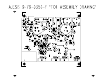
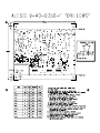
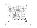
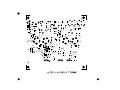
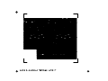
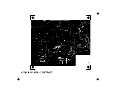
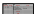
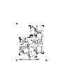
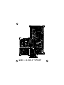
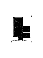
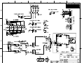
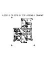
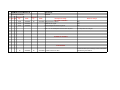
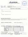
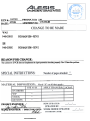
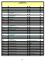
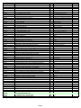
ALESIS
IO|2 (UB0)
Service Manual
P/N: 8-31-0137-A
ATTENTION!
THIS DOCUMENT CONTAINS SENSITIVE
PROPRIETARY INFORMATION.
ALL RECIPIENTS MUST HAVE A CURRENT
NON-DISCLOSURE AGREEMENT ON FILE
WITH ALESIS, LLC.
DO NOT MAKE ILLEGAL
COPIES OF THIS DOCUMENT
The information in this document contains privileged and confidential information.
It is intended only for the use of those authorized by Alesis. If you are not the
authorized, intended recipient, you are hereby notified that any review,
dissemination, distribution or duplication of this document is strictly prohibited. If
you are not authorized, please contact Alesis and destroy all copies of this
document. You may contact Alesis at [email protected] or at
[email protected].
Copyright Alesis, LLC
Confidential
Alesis Service Manual
8-31-0137-A
Preface
This document is intended to assist the service technician in the operation,
maintenance and repair of the Alesis device. Together with the User Reference
Manual, this document provides a complete description of the functionality and
serviceability of the Device. Any comments or suggestions you may have
pertaining to the document are welcome and encouraged.
READ THIS!
In addition to any purchase price that Alesis may charge as consideration for Alesis selling or
otherwise transferring this service manual (“Manual”) to you, if you are not a service and repair
facility (“Service Center”) authorized by Alesis in writing to be an authorized Service Center,
Alesis sells or transfers the Manual to you on the following terms and conditions:
Only Service Centers authorized by Alesis in writing are authorized to perform service and repairs
covered by an Alesis warranty (if any), and transfer of the Manual to you does not authorize you
to be an authorized Service Center. Therefore, if you perform, or if the Manual is used to
perform, any service or repairs on any Alesis product or part thereof, any and all
warranties of Alesis as to that product and any service contract with Alesis for that
product shall be voided and shall no longer apply for such product, even if your services
or repairs were done in accordance with the Manual.
All service or repairs done by you or with reference to the Manual shall be solely your
responsibility, and Alesis shall have no liability for any such repairs or service work. All such
service or repairs are performed at the sole risk of the person performing the service or
repairs. You agree that all such work will be performed in a competent, professional and safe
manner at all times and to indemnify and fully hold Alesis and its successors and assigns
harmless in the event of any failure to so perform.
Your purchase of the Manual shall be for your own ultimate use and shall not be for purposes of
resale or other transfer.
As the owner of the copyright to the Manual, Alesis does not give you the right to copy the
Manual, and you agree not to copy the Manual without the written authorization of Alesis. Alesis
has no obligation to provide to you any correction of, or supplement to, the Manual, or any new or
superseding version thereof.
Alesis shall have the right to refuse to sell or otherwise transfer repair parts or materials to you in
its sole discretion. You shall not use, sell or otherwise transfer spare or replacement parts
supplied by Alesis to you (i) to repair or be used in products manufactured for or by third parties
or (ii) to any third parties for any purpose.
You shall not make any warranties or guarantees with respect to the products of Alesis or the use
thereof on behalf of Alesis or in your own name.
The foregoing describes the entire understanding related to sale or transfer of the Manual to you,
and no other terms shall apply unless in a writing signed by an authorized representative of
Alesis.
All Trademarks are property of their respective companies.
Confidential
Alesis Service Manual
8-31-0137-A
Warnings
TO REDUCE THE RISK OF ELECTRIC SHOCK OR FIRE, DO NOT EXPOSE
THIS PRODUCT TO WATER OR MOISTURE.
The arrowhead symbol on a lightning flash inside a triangle is
intended to alert the user to the presence of un-insulated
"dangerous voltage" within the enclosed product which may be of
sufficient magnitude to constitute a risk of electric shock to persons.
The exclamation point inside a triangle is intended to alert the user
to the presence of important operating, maintenance and servicing
instructions in the literature which accompanies the product.
REPAIR BY ANY PERSON OR ENTITY OTHER THAN AN AUTHORIZED
ALESIS SERVICE CENTER WILL VOID THE ALESIS WARRANTY.
PROVISION OF THIS MANUAL DOES NOT AUTHORIZE THE RECIPIENT TO
COMPETE WITH ANY ALESIS DISTRIBUTOR OR AUTHORIZED REPAIR
SERVICE CENTER IN THE PROVISION OF REPAIR SERVICES OR TO BE
OR MAKE REPAIRS AS AN AUTHORIZED SERVICE CENTER.
ALL REPAIRS DONE BY ANY ENTITY OTHER THAN AN AUTHORIZED
ALESIS SERVICE CENTER SHALL BE SOLELY THE RESPONSIBILITY OF
THAT ENTITY, AND ALESIS SHALL HAVE NO LIABILITY TO THAT ENTITY
OR TO ANY OTHER PARTY FOR ANY REPAIRS BY THAT ENTITY.
Regarding the Power Supply Fuse
CAUTION: The product under service may employ the use of a
replaceable fuse. Danger of fire or electrocution if fuse is
incorrectly replaced. Replace with only the same type or
equivalent type recommended by the equipment manufacturer.
Regarding the Internal Battery
CAUTION: The product under service may employ the use of a
internal battery. Danger of explosion if battery is incorrectly
replaced. Replace only with the same or equivalent type
recommended by the manufacturer. Dispose of used batteries
according to the manufacturer's instruction.
Confidential
Alesis Service Manual
8-31-0137-A
Safety Instructions
Carefully read the applicable items of the operating instructions and these safety
suggestions before using this product. Use extra care to follow the warnings
written on the product itself and in the operating instructions. Keep the operating
instructions and safety suggestions for reference in the future.
1. Power Source. The product should only be connected to a power supply which is described
either in the operating instructions or in markings on the product.
2. Power Cord Protection. AC power supply cords should be placed such that no one is likely to
step on the cords and such that nothing will be placed on or against them.
3. Periods of Non-use. If the product is not used for any significant period of time, the product's
AC power supply cord should be unplugged from the AC outlet.
4. Foreign Objects and Liquids. Take care not to allow liquids to spill or objects to fall into any
openings of the product.
5. Water or Moisture. The product should not be used near any water or in moisture.
6. Heat. Do not place the product near heat sources such as stoves, heat registers, radiators or
other heat producing equipment.
7. Ventilation. When installing the product, make sure that the product has adequate
ventilation. Improperly ventilating the product may cause overheating, which may damage the
product.
8. Mounting. The product should only be used with a rack which the manufacturer
recommends. The combination of the product and rack should be moved carefully. Quick
movements, excessive force or uneven surfaces may overturn the combination which may
damage the product and rack combination.
9. Cleaning. The product should only be cleaned as the manufacturer recommends.
10. Service. The user should only attempt the limited service or upkeep specifically described in
the operating instructions for the user. For any other service required, the product should be
taken to an authorized service center as described in the operating instructions.
11. Damage to the Product. Qualified service personnel should service the unit in certain
situations including without limitation when:
a. Liquid has spilled or objects have fallen into the product,
b. The product is exposed to water or excessive moisture,
c. The AC power supply plug or cord is damaged,
d. The product shows an inappropriate change in performance or does not operate
normally, or
e. The enclosure of the product has been damaged.
Confidential
Alesis Service Manual
8-31-0137-A
ALESIS
IO|2 (UB0)
SCHEMATIC
AND
PCB
FILES
Confidential
Alesis Service Manual
8-31-0137-A
MAIN PCB
REV F
Confidential
Alesis Service Manual
8-31-0137-A
Last Revised:
3/17/2006
UB0MNF - Main PCB Rev F
RevChange Document
SCH PCB CAM
x
x
Suggested
DATE
by:
SOP
SOP
SOP
3/13/2006
3/13/2006
3/13/2006
Performed
DATE
by:
JK
3/17/2006
Description of change:
Reason for change:
TOP LEVEL CHANGES
Change all text from Rev E to F
update all Part Types
Review/Integrate all outstanding ECNs
SOP
SOP
SOP
Note: ***A new solderpaste stencil IS NOT required***
No SMD components were moved.
SCHEMATIC CHANGES
PCB CHANGES
x
JK
3/14/2006
JK
3/17/2006
x
YH
3/16/2006
JK
3/16/2006
x
YH
3/16/2006
JK
3/16/2006
x
YH
3/16/2006
JK
3/16/2006
x
YH
3/16/2006
JK
3/16/2006
x
YH
3/16/2006
JK
3/16/2006
Flood power plane.
The bottom layer pads of C75's negative terminal and
C76's positive terminal are too close.
The bottom layer pads of C43's negative terminal and
C44's positive terminal are too close.
The bottom layer pads of C57's negative terminal and
C68's positive terminal are too close.
The bottom layer pad of C40's negative terminal is too
close to C41's +3.3V via.
The bottom layer pad of C60's negative terminal is too
close to one of R68's pads.
The leads of the thru-hole components at these locations, after
being bent during the auto-insertion process (to prevent the
components from falling out), tend to short out against the
neighboring pads during the wave-solder process.
MAIN PCB
REV E
Confidential
Alesis Service Manual
8-31-0137-A
Last Revised:
3/13/2006
UB0MNE - Main PCB Rev E
RevChange Document
SCH PCB CAM
x
x
x
x
x
x
Suggested
DATE
by:
SOP
SOP
SOP
JK
12/2/2005
12/2/2005
12/2/2005
3/10/2006
Performed
DATE
by:
JK
JK
JK
3/13/2006
3/13/2006
3/13/2006
Description of change:
Reason for change:
TOP LEVEL CHANGES
Change all text from Rev D to E
update all Part Types
Review/Integrate all outstanding ECNs
SOP
SOP
SOP
Note: ***A new solderpaste stencil IS NOT required***
No components were changed or moved.
Correct implementation of input protection diodes and 100 - The current implementation does not provide much protection, if
Ohm series resistors.
any at all.
SCHEMATIC CHANGES
PCB CHANGES
MAIN PCB
REV D
Confidential
Alesis Service Manual
8-31-0137-A
Last Revised:
12/1/2005
UB0MND - Main PCB Rev D
RevChange Document
SCH PCB CAM
Suggested
DATE
by:
SOP
SOP
SOP
Performed
DATE
by:
Description of change:
TOP LEVEL CHANGES
Change all text from Rev C to #
update all Part Types
Review/Integrate all outstanding ECNs
10/26/2005
10/26/2005
10/26/2005
Reason for change:
x
x
x
x
x
x
x
x
MBL
MBL
11/16/2005
11/14/2005
AWS
x
x
MBL
11/14/2005
AWS
11/29/2005
Add 100ohm resistors between input DC blocking caps (C25, Protect negative voltage regulator from damage due to short. (This
30, 31, 35) and protection diodes (D3-10).
was implemented as rework pre-production so there is no ECN.)
x
x
AWS
AWS
11/28/2005
11/28/2005
AWS
AWS
11/28/2005
11/28/2005
Resize holes on MIDI jack footprint. 49.2mil for shield pin,
43.3 mil for other pins
Resize holes on XLR jack footprint
x
AWS
11/28/2005
AWS
11/28/2005
Modify 10mm PEB (PCB?) board edge to 13mm
Yahourng request
x
AWS
11/28/2005
AWS
11/28/2005
Modify footprint of 1-08-0222 for 1mm hole size
Yahourng request
x
AWS
11/28/2005
AWS
11/28/2005
Unplate corner mounting holes on main pcb
Yahourng request
Note: ***A new solderpaste stencil IS required***
Components were added.
12/1/2005
Reduce gain on guitar inputs by 3dB.
Change headphone volume control to pre-Master volume.
SCHEMATIC CHANGES
PCB CHANGES
SOP
SOP
SOP
Inputs will clip with standard guitar and gain at minimum
This is done on the Front Panel PCB.
Yahourng request
Yahourng request
MAIN PCB
REV C
Confidential
Alesis Service Manual
8-31-0137-A
Last Revised:
10/26/2005
UB0MNC - Main PCB Rev C
RevChange Document
SCH PCB CAM
x
x
x
x
x
x
Suggested
DATE
by:
SOP
SOP
SOP
YHT
10/12/2005
10/12/2005
10/12/2005
10/12/2005
Performed
DATE
by:
JK
JK
JK
10/26/2005
10/26/2005
10/26/2005
Description of change:
Reason for change:
TOP LEVEL CHANGES
Change all text from Rev B to C
update all Part Types
Review/Integrate all outstanding ECNs
SOP
SOP
SOP
Note: ***A new solderpaste stencil IS required***
A component was removed.
Ground the USB shield directly to GND instead of through
ferrite bead. Remove ferrite bead L2.
EMC compliance.
SCHEMATIC CHANGES
PCB CHANGES
UB0 Main PCB Rev.C Modifications
Insert 100ohm resistor in series with each of the DC blocking caps for the CH1 and CH2 input (C25, C30, C31, and C35).
Cut PCB traces (4 places) as indicated below:
Solder a 100ohm resistor onto PCB to bridge the cut (4 places):
FRONT PANEL
PCB
REV C
Confidential
Alesis Service Manual
8-31-0137-A
UB0FPA - Front Panel PCB Rev C
RevChange Document
SCH PCB CAM
x
Suggested
by:
DATE
Last Revised:
11/28/2005
Performed
by:
DATE
Description of change:
TOP LEVEL CHANGES
Change revision to Rev C
Update all Part Types
Review/Integrate all outstanding ECNs
SOP
SOP
SOP
9/21/2005
9/21/2005
9/21/2005
x
x
AWS
AWS
11/20/2005
11/28/2005
AWS
AWS
x
MBL
9/26/2005
AWS
11/28/2005
11/28/2005
Reason for change:
SOP
SOP
SOP
Resize drill hole in ribbon cables' footprints
Yahourng Request
Modify footprint of 1-08-0222 for 1mm hole size
Yahourng request
Change headphone volume control from post-Main volume
to pre, so that the Main and Headphone volumes are
11/20/2005 independent.
Multiple user requests.
Note: ***A new solderpaste stencil IS/IS NOT required***
SCHEMATIC CHANGES
PCB CHANGES
FRONT PANEL
PCB
REV B
Confidential
Alesis Service Manual
8-31-0137-A
UB0FPB - Front Panel PCB Rev B
RevChange Document
SCH PCB CAM
Suggested
by:
SOP
SOP
SOP
DATE
9/20/2005
9/20/2005
9/20/2005
Last Revised:
9/21/2005
Performed
by:
JK
DATE
Description of change:
TOP LEVEL CHANGES
9/21/2005 Change revision to Rev B
Update all Part Types
Review/Integrate all outstanding ECNs
Note: ***A new solderpaste stencil IS NOT required***
Reason for change:
SOP
SOP
SOP
No components are changed.
SCHEMATIC CHANGES
PCB CHANGES
JK
9/20/2005
JK
9/21/2005 Increase hole size for LEDs.
Current hole size is just a little tight, which would make
manufacturing more difficult.
ALESIS
IO|2 (UB0)
ECN
HISTORY
Confidential
Alesis Service Manual
8-31-0137-A
ENGINEERING CHANGE NOTICE
ECN #:
DATE:
LGO7401
3/15/06
PRODUCT(S):
UBO
'
ASSEMBL Y(S): 9-79-0350-£0
WAS
9-40-0350-D
PCB MAIN UBO- REV D
IS
9-40-0350-E
PCB MAIN UBO- REV E
REASON FOR CHANGE:
i
~
PRo~r~~~~~~~~
~;GiNEiR;- -, DlREcr~~
~-~
'-'-'---'-'-'-.".."""
"-".'-
ALESIS
IO|2 (UB0)
BOM
Confidential
Alesis Service Manual
8-31-0137-A
UB0 BOM
September 22, 2005
Note: Vendor is free to add/change/delete hardware (screws, nuts, etc.) in this BOM to optimize manufacturability.
P/N
DESCRIPTION
7-51-1219
UL CONFIGURATION
SHEET WELCOME-TO-ALESIS-FAMILY 5 x 8"
4-71-0015
7-22-0016
7-50-0200
7-51-0173
7-80-0391
7-80-0390
7-91-1002
7-94-xxxx
LABOR
LITERATURE/PACKAGING
CABLE USB 2 METERS A/B
SOFTWARE CD UB0
STICKER BARCODE S/N UB0
REF MANUAL, UB0
BOX SHIPPING UB0
BOX GIFT UB0
GEL SILICA 5G PACKET
POLYBAG
LABOR
TBD BY VENDOR
9-01-0088
9-11-0053
9-11-0054
9-15-0405
9-15-0406
9-23-0018
TOP LEVEL MECHANICALS
SCREWS, MISC
CHASSIS EXTRUDED ALUMINUM UB0
COVER REAR PANEL MOLDED PLASTIC UB0
COVER FRONT PANEL MOLDED PLASTIC UB0
LENS TINTED PLASTIC UB0
KNOB PLASTIC ELECTROPLATED UB0
FOOT RUBBER DOME CA
9-79-0350
9-79-0378
TOP LEVEL ELECTRICALS
ASSY PCB MAIN UB0
ASSY PCB FRONT PANEL UB0
9-79-0350
0-15-0101
0-15-0109
0-15-0152
0-15-0153
0-15-0221
0-15-0331
0-15-0473
0-15-0514
0-15-0750
0-16-1001
0-16-1002
0-16-1003
0-16-1182
0-16-1211
0-16-1302
0-16-1829
0-16-2001
0-16-2749
ASSY PCB MAIN UB0
RES 100 OHM 1/10W 5% 0805
RES 1.0 OHM 1/10W 5% 0805
RES 1.5K OHM 1/10W 5% 0805
RES 15K OHM 1/10W 5% 0805
RES 220 OHM 1/10W 5% 0805
RES 330 OHM 1/10W 5% 0805
RES 47K OHM 1/10W 5% 0805
RES 510K OHM 1/10W 5% 0805
RES 75 OHM 1/10W 5% 0805
RES 1.00K OHM 1/10W 1% 0805
RES 10.0K OHM 1/10W 1% 0805
RES 100K OHM 1/10W 1% 0805
RES 11.8K OHM 1/10W 1% 0805
RES 1.21K OHM 1/10W 1% 0805
RES 13.0K OHM 1/10W 1% 0805
RES 18.2 OHM 1/10W 1% 0805
RES 2.00K OHM 1/10W 1% 0805
RES 27.4 OHM 1/10W 1% 0805
QTY REF
1
1
1
1
1
0.05
1
1
1
1 FINAL ASSY AND TESTING
18
1
1
1
1
5
4
1
1
8
10
1
8
2
3
7
1
1
11
11
16
2
8
2
2
5
2
Page 1
R1-2 R4 R24 R66 R93 R104 R115
R12-15 R42-45 R97 R119
R17
R34-37 R51-52 R54-55
R9 R101
R11 R61 R71
R38-39 R56-57 R98-100
R47
R16
R3 R5-6 R18 R20-21 R23 R85-86
R7 R25-26 R28-29 R41 R48 R65 R69
R27 R32-33 R40 R49-50 R53 R68 R79
R134-135
R67 R76-77 R88-89 R91 R94-95
R121-122
R78 R90
R10 R60 R64 R70 R74
R19 R22
0-16-2941
0-16-3321
0-16-3402
0-16-3831
0-16-3921
0-16-5361
0-16-6811
0-16-7501
0-17-0101
1-07-0224
1-08-0222
1-12-0472
1-16-1103
1-55-0189
1-55-0222
1-55-0223
1-55-0470
1-55-0471
1-56-0101
1-56-0102
1-56-0104
1-56-0150
1-71-3102
2-50-4148
2-51-0140
2-51-4401
2-51-4403
2-54-0856
2-54-2114
2-54-6306
2-61-2985
2-61-3578
2-61-7223
2-62-0157
2-65-0017
2-69-2464
2-70-1020
2-71-3079
2-74-0181
2-75-4265
2-75-4344
2-84-8416
2-85-0403
4-00-0002
4-01-0008
4-02-0010
4-02-0011
4-05-0025
4-08-0402
4-14-1200
7-01-0048
7-20-0070
7-20-0073
7-40-8865
9-40-0350-B
LABOR
RES 2.94K OHM 1/10W 1% 0805
RES 3.32K OHM 1/10W 1% 0805
RES 34.0K OHM 1/10W 1% 0805
RES 3.83K OHM 1/10W 1% 0805
RES 3.92K OHM 1/10W 1% 0805
RES 5.36K OHM 1/10W 1% 0805
RES 6.81K OHM 1/10W 1% 0805
RES 7.50K OHM 1/10W 1% 0805
RES CHIP ARRAY 4 X 100 OHM 1/16W 5% ISOLATED C-C=0.8mm
CAP 2200uF ELEC 20% 6.3V 5x10.2x20mm
CAP 22uF ELEC 16V 20% 1.5x4x7mm
CAP 47uF ELEC 20% 63V 2.5x6.3x11mm
CAP 100uF ELEC LOW-ESR 20% 35V 105øC 2.5x6x11mm
CAP 18pF NPO 0805
CAP 2200pF NPO 0805 50V
CAP 0.022uF X7R 0805 50V
CAP 47pF NPO 0805 50V
CAP 470pF 5% NPO 0805 50V
CAP 100pF NPO 0805 5% 50V
CAP 1000pF NPO 0805 5% 100V
CAP 0.1uF X7R 0805 10% 50V
CAP 15pF NPO 0805
CAP 10uF TANT-B 16V
DIODE SIGNAL LS4148 MELF
DIODE POWER SCHOTTKY MBRS140LT3 40V 1A
TRANS NPN 2N4401 40V 1A SOT-23
TRANS PNP 2N4403 40V 800mA SOT-23
TRANS SMALL-SIGNAL PNP 65V 100mA BC856 SOT-23
TRANS SMALL-SIGNAL NPN 2SD2114K SOT-23
TRANS SMALL-SIGNAL DUAL P-CHAN EN-MOSFET FDC6306P ISOLATE
IC REG VOLTAGE LP2985IM5-4.0 LDO 4V 150mA SOT23-5
IC REG VOLTAGE IC REG VOLTAGE LM3578A ADJ 100KHz PWM SWITC
REG VOLTAGE NJU7223DL1-33 3.3V TO-252
IC 74AHC157 QUAD 2-TO-1 LINE DEMUX SOP-16
IC 74LVC1G17 SINGLE GATE SCHMITT-TRIG BUF
IC EEPROM SERIAL 64K-BIT 24C64 SOIC-8
IC MPU TAS1020B USB TQFP-48
IC MC33079 QUAD-OP-AMP SOP-14
IC OPTO-ISOLATOR TLP181 TRANS-OUT SMD
IC CODEC CS4265 24-BIT STEREO LOW-POWER QFN-32
IC CONVERTER D/A CS4344 24-BIT 192KHZ (I2S) TSSOP-10
IC RECEIVER DIG AUDIO 192kHz CS8416 TSSOP-28
IC VOLTAGE INVERTER CHARGE PUMP UNREG TPS60403 SOT23-5
JACK DIN 5-PIN MIDI PCB MOUNT 180° W/SHIELD
JACK RCA DUAL FEMALE PANEL-MNT/HOR-MNT
JACK 1/4 4-PIN FEM PCB MNT 90-DEG
JACK 1/4 STEREO 5-PIN FEM PCB-MNT VERT W/ BUSHING
JACK XLR 3-PIN FEM PCB-MNT VERT
CON USB 4-PIN FEMALE PC-MNT HORIZONTAL
HEADER DIL 12-PIN 2mm MALE 90° SHRD
CRYSTAL 6MHz PARALLEL 16pF HC-49US
INDUCTOR FERRITE BEAD 120 OHMS @ 100MHZ 0805
INDUCTOR POWER 330uH 0.61A 5x10.5x10.5mm
TRANSFORMER 1-10 mHz PULSE 1:1
PCB, MAIN UB0 REV B
LABOR
9-79-0378
0-09-0046
0-09-0047
ASSY PCB FRONT PANEL UB0
POT 10KA DUAL VERT 15mm D-SHAFT
POT 10KB DUAL VERT 15mm D-SHAFT
2
9
2
2
5
2
2
8
4
2
34
5
3
3
6
1
4
24
9
5
40
4
2
11
1
2
5
4
6
2
1
1
2
1
1
1
1
3
1
1
1
1
1
2
1
2
4
2
1
3
1
2
1
1
1
345
2
1
Page 2
R125-126
R30-31 R84 R108 R113 R117 R120
R124 R127
R133 R136
R46 R62-63 R72-73
R129-130
R114 R118
R81-83 R87 R105-107 R111
R8 R58-59 R103
C66 C81
C5 C8-9 C14-15 C19 C23 C37 C39-40
C25-26 C30-31 C35
C17 C32-33
C104 C108-109
C111 C125-129
C134
C94-95 C118 C131
C87-92 C96-97 C99-102 C105-106
C93 C98 C107 C113 C116-117 C121
C103 C110 C130 C135-136
C1-4 C6-7 C10-13 C16 C18 C20-22
C119-120 C132-133
C28-29
D2-12
D1
Q3 Q5
Q2 Q11-12 Q15-16
Q6-9
Q1 Q4 Q10 Q13-14 Q17
U6-7
U8
U10
U1 U3
U14
U5
U12
U11
U13 U16 U18
U2
U4
U17
U15
U9
J6-7
J2
J4-5
J9-10 J12-13
J8 J11
J1
J14-16
X1
L2-3
L1
T1
P3 P5
P4
0-09-0052
0-15-0100
0-16-1001
0-16-1002
0-16-1003
0-16-1401
0-16-2941
0-16-3321
0-16-4752
0-16-4991
0-16-5621
0-17-0102
1-08-0222
1-55-0471
1-56-0101
1-56-0104
1-56-0150
2-50-4148
2-71-3079
2-71-7082
2-72-0339
3-02-0057
3-02-0058
3-02-0059
4-02-0011
4-15-0406
6-01-0011
x-xx-xxxx
x-xx-xxxx
9-40-0378-A
LABOR
POT 5KC SINGLE VERT 15mm D-SHAFT
RES 10 OHM 1/10W 5% 0805
RES 1.00K OHM 1/10W 1% 0805
RES 10.0K OHM 1/10W 1% 0805
RES 100K OHM 1/10W 1% 0805
RES 1.40K OHM 1/10W 1% 0805
RES 2.94K OHM 1/10W 1% 0805
RES 3.32K OHM 1/10W 1% 0805
RES 47.5K OHM 1/10W 1% 0805
RES 4.99K OHM 1/10W 1% 0805
RES 5.62K OHM 1/10 1% 0805
RES CHIP ARRAY 4 X 1K OHM 1/16W 5% ISOLATED c-c=0.8mm SMD
CAP 22uF ELEC 16V 20% 1.5x4x7mm
CAP 470pF 5% NPO 0805 50V
CAP 100pF NPO 0805 5% 50V
CAP 0.1uF X7R 0805 10% 50V
CAP 15pF NPO 0805
DIODE SIGNAL LS4148 MELF
IC MC33079 QUAD-OP-AMP SOP-14
IC NJU7082BM DUAL POWER OP-AMP LOW VOLTAGE SOP-8 0.2
IC LM339 ANALOG COMP SOP-14
LED GREEN 1.1mm X 3.4mm RECT
LED YELLOW 1.1mm X 3.4mm RECT
LED RED 1.1mm X 3.4mm RECT
JACK 1/4 STEREO 5-PIN FEM PCB-MNT VERT W/ BUSHING
HEADER SIL 4-PIN 2mm MALE SHRD
SWITCH SLIDE DPDT 2MM-PITCH
HEADER DIL 12-PIN 2mm STAKED
HEADER 4-PIN SIL 2mm STAKED
PCB, FRONT PANEL UB0 REV A
LABOR
Page 3
2
2
2
11
8
1
1
3
1
2
1
3
14
2
2
4
2
3
1
1
2
7
2
3
1
1
5
3
1
1
94
P1-2
R3 R5
R7-8
R2 R6 R17 R22-25 R27 R30 R34-35
R18-21 R28-29 R32-33
R10
R11
R1 R4 R12
R13
R26 R31
R9
R14-16
C1 C3 C6-7 C12-16 C19-20 C22-24
C8-9
C2 C5
C4 C10-11 C18
C17 C21
D7 D10-11
U4
U1
U2-3
D5-6 D8-9 D12 D14-15
D3-4
D1-2 D13
J2
J1
S1-5
J4-6
J3