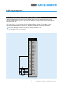
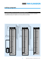
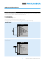
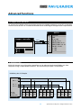
1
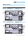
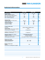
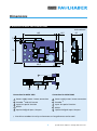
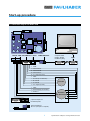
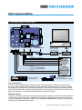
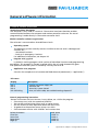
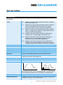
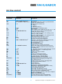
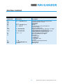
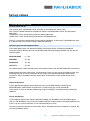
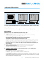
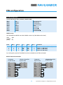
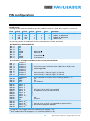
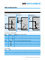
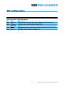
Motion Controller 4-Quadrant PWM for DC-Micromotors and Brushless DC-Servomotors Series MCDC 3603 Series MCBL 3603 Operating Instructions c om ww w. fau l h er. b a Miniature Drive Systems Micro Drives DC-Micromotors Precision Gearheads Servo Components Drive Electronics Surf to the following Internet address and you will find the latest edition of the instruction manual on-line: www.minimotor.ch/uk/pr/ For direct Download: http://www.minimotor.ch/minicatalog/pdf/DriveCircuits/Manuals/IM_e_MCDC_MCBL_3603.pdf Index Chapter Page 1. Description 2 2. Model overview 3 3. Technical information 4 4. Dimensions 5 5. Start-up Procedure 6 6. Connection diagram for MCBL 3603 7 7. Connection diagram for MCDC 3603 8 8. General software information 9 9. Set up values 10 10. On line control 11-12 11. System parameter set-up 13 12. Call up program from normal inputs 14 13. Call up program from binary coded digital inputs 15 14. Example of sequential multi-axis application 16 15. Analogue input command 17 16. Stepper motor emulation 18 17. RS485easy-Bus 18. Trouble-shooting 20 19. Operating system error 20 20. General usage instructions 21 21. Hardware 22 22. Pin configuration 23-26 Note 27-29 18-19 Description 1. Description The MCBL 3603 and the MCDC 3603 are very compact motion controllers ideal for our brushless DC-Servomotors and brushed DC-Micromotors. Each model comprises a PWM servo amplifier. Technology Both motion controllers are based on a fast, powerful 16 bit microcomputer system. This guarantees high dynamics, precise positioning and quiet running, regardless of the motor type used. The well thought-out design and consistent application of SMD technology ensures a very compact device. The specially developed user software offers high flexibility and simple handling. Application field Developed with the use of state-of-the-art technology, the motion controllers are suitable for a wide range of applications: insertion and handling machines, machine tools, robots, X/Y tables, drive and automation systems in medical technology, chemical and food industry, etc. Programming One of the most important objectives in the development of these units was to keep its operation as simple as possible. This has been attained with the use of just a few, highly efficient functions. Manual balancing or potentiometers are no longer required. Menu-guided program and parameter-editing functions are already integrated for operation with an ASCII terminal. In place of internal menu management, the clearly structured command set can be simply integrated into a customer-specific interface, e.g. with Visual Basic, Lab View, Pascal, C++, etc. Any PC with Windows operating system can be used as an input terminal. Program updates are made directly via the serial interface without changing the hardware. Communication is made via the serial port RS232 or RS485. We advise the use of the software WINMOTION® for an easy programming of Motion Controllers provided with Firmware 4.10. 2 Specifications subject to change without notice Model overview 2. Model overview MCBL 3603 Integrated PWM servo amplifier 36V-3A REMOTE CONTROL PROGRAM 1-15 RS232 RS485 RS485easy-Bus MENUE SET UP HOME FUNCTION PROGRAM INDEX PROGRAM MOTION UP DATE PROGRAM SAVE/LOAD APPLICATION ANALOGUE, PULSE DIR, A/B ENC 2 (OPTIONAL) ACCELERATION SPEED POSITION Brushless DC-Servomotors with encoder PROPORTIONAL INTEGRAL DERIVATIVE VELOCITY f(P,I,D) CURRENT LIMIT TEMP SENSOR I Peak OVER VOLT I Nominal MONITOR BALLAST CIRCUIT f(I) f(V) QUADRATURE COUNTER POWER STAGE COMMUTATION LOGIC CURRENT SENSOR DIFFERENTIATOR PH A PH B PH C HA A HA B HA C CH A CH B 8 OUTPUT DIGITAL PLC LOGIC INPUT FUNCTION BCD-CODED PROGRAM SWITCHED POWER SUPPLY 5V, 12V INTERNAL MCDC 3603 REMOTE CONTROL PROGRAM 1-15 RS232 RS485 RS485easy-Bus ANALOGUE, PULSE DIR, A/B ENC 2 (OPTIONAL) MENUE SET UP HOME FUNCTION PROGRAM INDEX PROGRAM MOTION UP DATE PROGRAM SAVE/LOAD APPLICATION ACCELERATION SPEED POSITION SWITCHES HOME SENSOR LIMIT SENSOR EMERGENCY CIRCUIT EXTERNAL PLC ECT OPTIONAL Integrated PWM servo amplifier 36V-3A Brushed DC-Micromotors with encoder PROPORTIONAL INTEGRAL DERIVATIVE VELOCITY f(P,I,D) CURRENT LIMIT TEMP SENSOR I Peak OVER VOLT I Nominal MONITOR BALLAST CIRCUIT f(I) f(V) QUADRATURE COUNTER DIFFERENTIATOR POWER STAGE + - 8 OUTPUT DIGITAL PLC LOGIC INPUT FUNCTION BCD-CODED PROGRAM 12 INPUT DIGITAL SWITCHED POWER SUPPLY 5V, 12V INTERNAL OPTIONAL 3 SERVOMOTOR DC-Micromotor BRUSHLESS CURRENT SENSOR CH A CH B POWER DC Encoder VALVE RELAY EXTERNAL PLC ECT. 12 INPUT DIGITAL POWER DC Brushless SERVOMOTOR DC-Servomotor BRUSHLESS Encoder VALVE RELAY EXTERNAL PLC ECT. SWITCHES HOME SENSOR LIMIT SENSOR EMERGENCY CIRCUIT EXTERNAL PLC ECT Specifications subject to change without notice Technical information 3. Technical data Electrical data Supply voltage PWM switching frequency Max. continuous output current Max. peak output current Max. encoder frequency MCBL 3603 Software data Program memory (16 bit access) Sampling period Number of programs Lines per program Number of indexes Communication data Interface Status display Optional inputs (5V pull-up standard, 24V pull-down on request) 12 ÷ 36 20 3 10 200 12 ÷ 36 20 3 10 200 V DC kHz A A kHz 256 x 8 500 15 50 50 256 x 8 500 15 50 50 kbyte µs RS232 / RS485 / RS485easy-Bus 3 LED's 12 (optional) Optional outputs (6 x 50V/500mA open collector, 2 x TTL level) Program and parameter editor Program up-date Application and parameter save / load Starting position function MCDC 3603 8 (optional) integrated ASCII terminal via serial interface via serial interface via encoder Z-index / via external sensor Temperature rating Operating temperature Storage temperature 0 ... + 55 -20 ... + 80 Weight / Dimensions Weight: Dimensions: see diagram on page 5 130 4 °C °C g Specifications subject to change without notice Dimensions 4. Dimensions for MCBL 3603 and MCDC 3603 Scale reduced 105 7,5 10,5 35 3,2 75 66,7 3 2,9 99,2 5 1 2 4 3 Connection for MCBL 3603 Connection for MCDC 3603 1 Power supply motor / motor connection 1 Power supply motor / motor connection 2 Encoder 1) and Hall sensors 2 Encoder 1) 3 Input for special function 3 Input for special function 4 RS232 4 RS232 5 Optional digital Input / Output 5 Optional digital Input / Output 1) Line driver encoders for noisy environments or long distances can be used. 5 Specifications subject to change without notice Start-up procedure 5. Start-up procedure Here we list a step-by-step start-up procedure for both the electrics and software. Also included are several examples in order to allow the user to test the unit and familiarise himself with programming. We therefore recommend that this sequence is followed for trouble-free installation: Start-up Procedure for MCBL 3603 Connect the motor phases to MOTOR Connect the encoder and the motor Hall sensor leads to ENCODER HALL Connect the RS232 (or RS485) to the computer port COM Connect the power supply to PWR Power the motion controller Software start-up Start-up Procedure for MCDC 3603 Connect the motor terminals to MOTOR Connect the encoder to ENCODER Connect the RS232 (or RS485) to the computer port COM Connect the power supply to PWR Power the motion controller Software start-up The computer link is necessary to program the motion controller. After programming has been completed, the computer link can be disconnected since the programs can be started using the motion controller input functions. For advanced functions such as: Analogue input command Stepper motor emulation RS 485 serial interface Multi-axis operation please refer to the specifique chapters 6 Specifications subject to change without notice Start-up procedure 6. Connection diagram for MCBL 3603 MOTOR PWR ENCODER HALL OPTIO 5 1 11 6 1 15 10 5 COMPUTER INPUT Computer cable RS232 / RS485 RS485easy-Bus* COM1 1 1 GND 9 Hall sensor A 11 Hall sensor B 13 Hall sensor C 15 Vcc logical (5 VDC) 1 GND 7 Z index (if no index NC) 3 B channel Encoder 5 A channel 2 Vcc logical (5 VDC) 1 GND 2 Power Supply (12-50 VDC) 3 Phase A Brushless 4 Phase B DC-Servomotor 5 Phase C *optional adapter for RS 485easy-Bus optional digital I/O PLC I/O (12 inputs / 8 outputs) 7 Specifications subject to change without notice Start-up procedure 7. Connection diagram for MCDC 3603 MOTOR PWR 5 1 ENCODER 11 6 1 15 10 5 OPTIO COMPUTER INPUT Computer cable RS232 / RS485 RS485easy-Bus* COM1 1 1 GND 7 Z index (if no index NC) 3 B channel Encoder 5 A channel 2 Vcc logical (5 VDC) 1 GND 2 Power Supply (12-50 VDC) 3 Motor (-) DC-Micromotor 4 Motor (+) *optional adapter for optional digital I/O PLC I/O (12 inputs / 8 outputs) RS 485easy-Bus PLC I/O description The PLC I/O port enables direct communication with the position control function without having to use a computer. For example, once a program has been created, it can be executed by simply giving a command to the assigned input. In the initial phases of installation, and to allow the user to better understand the operation of the motion controller, all instructions are given via computer. It is therefore not necessary to connect this port. RS232 description This port is the communication link between the motion controller and the external computer via the COM1 connection point. Additional information regarding the connection and set-up is given in chapter 29. The link is make with a standard computer cable which, if necessary, can be optionally supplied by Minimotor. 8 Specifications subject to change without notice General software information 8. General software information Terminal emulator description The computer is only used as a terminal. The terminal emulator therefore enables communication between the computer and motion controller software. The actual programming is made directly in the motion controller itself. Motion controller software organisation The software is constructed on three different levels. Operating system The operating system normally remains invisible to the user and is a background function for: – download functions – back-up in emergency situations For additional information, see chapter 26. Program xx36_yyy.S19 Is the basic working program which realises all described functions and programming possibilities. This program is already installed within the unit and automatically goes into operation once the system is started-up. Actualy version 4.10 Application user programs Contains the complete set of customer-defined data and parameters (= “application”). LED status Display LED 1 LED 2 LED 3 LED 3 blinking Description Internal 5V power supply OK Software OK Servo OK, system closed Error, ask error code, see troubleshooting chapter 27 General programming instructions General instructions on how to move, insert, delete, etc. within the program: • • • • • Close every entry with the command <ENTER> Text can be entered using either small or capital letters Use the arrows to move up and/or down the menu lines To go back to the previous menu always use <ESC> Close erroneous entries with <ENTER> and re-enter data Delete characters Clear line Insert line Page down Page up Back Space <CRTL C> <CRTL I> <CRTL D> <CRTL U> 9 Specifications subject to change without notice Set up values 9. Set up values Description MODE 0= Programs and commands operated using the standard inputs (see chapter 19) 2= Programs and commands operated using the standard inputs. PULSE/DIRECTION input signal for stepper control emulation function active (see chapter 23) 3= Programs and commands operated using the standard inputs. Analogue input signal for digital speed control function active (see chapter 22) 10 = Programs operated using the 4 binary coded inputs and input 8 as starting trigger (see chapter 20) 12 = Programs operated using the 4 binary coded inputs and input 8 as starting trigger. Stepper control emulation function active (see chapter 23) 13 = Programs operated using the 4 binary coded inputs and input 8 as starting trigger. Analogue input signal for digital speed control function active (see chapter 22) I NOM Nominal current I PEAK Peak current PROPORTIONAL Proportional closed loop parameter (stiffness) INTEGRAL Integral closed loop parameter (positioning precision) DERIVATIVE Differential closed loop parameter (stability, dynamic) VELOCITY Velocity closed loop parameter (oscillation prevention) INC PER PULSE Increment (lines) per pulse in MODE 2 or 12 for stepper emulation function (see chapter 23) DEVIATE POS Permissible max. position deviation in lines PROFILE ROUND To smooths the speed profile out (see below) v v profile round 10 = 5 ms 100 = 50 ms t t By setting to profile round, the speed profile is smoothed out, this reducing mechanical stress for better live performance. INPUT H-ACTIVE 0=Input active low, I=Input active ANALOG FUNCTION Analog function active with mode 3 or 13 for digital speed control. 0=CW (+), I=CCW (-), 2=Cw and CCW (+/-) 10 Specifications subject to change without notice On line control 10. On line control Command Parameter Description lines/s2 AC AIX 1 000 - 4 000 000 10 - 50 000 (x 1 000) lines/s2 ANF 0-2 CI CO CLO DIX 0-100 1-8 0-1 ± 2 000 000 000 lines DRH 1-2 DRZ 1-2 DP DV EC ED lines 0 - 50 GP GW GZ HO HOF 1 000 - 5 000 000 lines/s2 0 - 100 000 increment ICP IHA IN INH IP IT IX JP JN JNZ[letter] 1 - 50 0-1 1 - xx 1-8 1 - xx 0 - 50 1 - 50 NIX 1 - 50 PG PO PP PRF 1 - 15 ± 2 000 000 000 lines 1 - 50 1 - 100 PQ PW PWC RI *RI RR RW SET[letter] 0 - 100 1 - 99 1 - 10 000 1 - 10 000 1 - 10 000 1 - 50 Acceleration Overwrite acceleration index at preloaded NIX number by remote control Analog function mode 3/13 0 = CW (+) 1 = CCW (-) 2 = CW and CCW (+/-) Card identifier for RS485easy-Bus Clear output Clear outputs after HOME function 0 = no, 1 = yes Overwrite distance index at preloaded NIX number by remote control Direction of motor rotation, for seeking coarse sensor 1 = CW, 2 = CCW Direction of motor rotation, for seeking Z mark sensor 1 = CW, 2 = CCW Permitted position deviation in lines Differential closed loop parameter Encoder counter on-line diagnosis Emergency deceleration with Exit function EE and Limit-switch function LL and LR Go to position (absolute) Go way (relative) Go to Z-index (encoder) HOME function according to program Offset after edge coarse sensor no stop same direction, if HOF is not 0 this value is indicated on HOME menu Inc. per pulse, mode 2/12, pulse / direction control 0 = input low active, 1 = input high active Nominal current HOME sensor input number Peak current Integral closed loop parameter Run index # according to program Jog (run) positive, constant speed Jog (run) negative, constant speed Indicate loop reference letter (from A to E). Decrements the loop repeats, whereby if not zero, jump to line xx Number index pre-load for changing index parameters by remote control Run program # Position (absolute) Proportional closed loop parameter Rounding of speed profile (should be value), smooth start and smooth stop Servo amplifier power OFF Power ON, reset position counter Power ON continue, keep position counter Required identifier for RS485easy-Bus Get back identifier, position, and status complete Repeat way CW/CCW Repeat way (same direction) Set loop reference letter (five possibilies, from A to E) and number of repeats xxxx 11 Specifications subject to change without notice On line control Command Parameter Description SIX 25 - 1 000 000 lines/s SM SO SP SR 1-8 25 - 1 000 000 lines/s ± 1 - 100 :10 TE TGD ± 2 000 000 000 TGU ± 2 000 000 000 TI TP TS ? or 1 - 12 VL WA WT 1 - 50 ± 2 000 000 000 lines x 10 ms Overwrite speed index at preloaded NIX number by remote control Stop motion Set output Speed Synchronisation ratio with optional second encoder Tell error codes 01-99 Trigger downward count, absolute, at output x (5 ms) defined in output function Trigger upward count, absolute, at output x (5 ms) defined in output function Tell status input, 0=Low 1=High Tell actual position ± 2*10E9 Tell status: 0 = power OFF 1 = power ON 2 = moving 3 = program active 9 = error Velocity closed loop parameter Way (relative) Waiting time 12 Specifications subject to change without notice Set-up values 11. System parameter set-up Current limiter set up The current limits I NOM and I PEAK must be set according the motor used. The value of I NOM should not exceed the motor’s recommended current for continuous operation. I NOM limit is only active during constant speed operation. I PEAK limit is only active during acceleration and deceleration. There is a continuous monitoring of incremental feedback. If the motor is blocked more than 0,5 seconds then the current will be automatic reduced. Optimising the closed loop parameters The closed loop system can be optimised by running the motor (including assembled mechanical parts) directly on line and by adjusting the following parameters via the SET UP VALUES menu: PROPORTIONAL (1 - 50) INTEGRAL (0 - 50) DERIVATIVE (0 - 50) VELOCITY (0 - 50) This optimisation is best carried out by running the motor with the RW and/or RR instructions. When executing these instructions, all parameters (even set-up) can be changed on line, thus enabling the user to see the reaction of the system whilst making changes. One helpful function is the EC (encoder counter) which gives information on the actual motor shaft position. Improved dynamics If your application requires more dynamics, this can be obtained by increasing the PROPORTIONAL, DERIVATIVE and VELOCITY LOOP values (e.g. to 10, 20 and 20). If the motor is noisy or vibrates (indicating system instability), these parameters should be reduced. Precise positioning If you need to improve the motor’s position holding, an INTEGRAL value should be given (e.g. 5). The INTEGRAL value is only activated when the motor reaches the requested position. In this way the system’s dynamic is not influenced by this value. To control the exact position of the motor, the EC (encoder counter) command is used via the ON LINE CONTROL menu. 13 Specifications subject to change without notice Call up program 12. Call up program from normal inputs (Optional I/O) The procedure to execute a program or another instruction via the 8 normal inputs is as follows. assign the instruction to the desired input via the INPUT FUNCTION menu activate the input via an external circuit (see example below) PLC I/O PIN 1 2 3 4 5 6 7 8 9 10 11 12 17 18 19 20 21 22 23 24 13 14 15 16 Function OUT 1 OUT 2 OUT 3 OUT 4 OUT 5 OUT 6 OUT 7 OUT 8 COM GND GND VCC IN 1 IN 2 IN 3 IN 4 IN 5 IN 6 IN 7 IN 8 IN 9 IN 10 IN 11 IN 12 14 Specifications subject to change without notice Call up program 13. Call up program from BCD coded digital inputs (Optional I/O) When the application uses more than 8 digital inputs, the user should call them up via the BCD coded digital inputs. In this case, the MODE in SET-UP VALUES menu should be set to 10 (or 12 or 13). The input lines 9 - 12 are used as binary coded program numbers. The trigger to start the pre-selected program is input line 8. Program number 0 is not used. Therefore: pre-select program number with binary-switch (numbers 1-15) start program with start button S PLC I/O PIN S Function OUT 1 OUT 2 OUT 3 OUT 4 OUT 5 OUT 6 OUT 7 OUT 8 COM GND GND VCC IN 1 IN 2 IN 3 IN 4 IN 5 IN 6 IN 7 IN 8 IN 9 IN 10 IN 11 IN 12 1 2 3 4 5 6 7 8 9 10 11 12 17 18 19 20 21 22 23 24 13 14 15 16 BCD 15 Specifications subject to change without notice Call up program 14. Example of sequential multi-axis application (optional I/O) The program number and program start of the sequential follow-on motion controllers are specified through the output of the lined up motion controller. PLC I/O PIN Function S BCD 1 2 3 4 5 6 7 8 9 10 11 12 17 18 19 20 21 22 23 24 13 14 15 16 OUT 1 OUT 2 OUT 3 OUT 4 OUT 5 OUT 6 OUT 7 OUT 8 COM GND GND VCC IN 1 IN 2 IN 3 IN 4 IN 5 IN 6 IN 7 IN 8 IN 9 IN 10 IN 11 IN 12 Motion Controller 1 PLC I/O PIN Function 1 2 3 4 5 6 7 8 9 10 11 12 17 18 19 20 21 22 23 24 13 14 15 16 OUT 1 OUT 2 OUT 3 OUT 4 OUT 5 OUT 6 OUT 7 OUT 8 COM GND GND VCC IN 1 IN 2 IN 3 IN 4 IN 5 IN 6 IN 7 IN 8 IN 9 IN 10 IN 11 IN 12 Motion Controller 2 16 PLC I/O PIN Function 1 2 3 4 5 6 7 8 9 10 11 12 17 18 19 20 21 22 23 24 13 14 15 16 OUT 1 OUT 2 OUT 3 OUT 4 OUT 5 OUT 6 OUT 7 OUT 8 COM GND GND VCC IN 1 IN 2 IN 3 IN 4 IN 5 IN 6 IN 7 IN 8 IN 9 IN 10 IN 11 IN 12 Motion Controller 3 Specifications subject to change without notice Advanced functions 15. Analogue input command To activate the analogue input command function the MODE parameter in the SET UP VALUES menu must be set to 3 or 13 and the ANALOG FUNCT to: 0 for CW operation 1 for CCW operation 2 for CW and CCW operation The maximum speed is defined with the SP command. For high dynamics we recommend increasing the AC value (AC > 2 000 000). External voltage OPTIO PIN 1 2 3 4 5 6 7 8 Function GND 5V or 10V PULSE / ch. B DIRECTION / ch. A DIRECTION* / ch. A* PULSE* / ch. B* +/- 10V 0 - 10V Potentiometer OPTIO PIN 1 2 3 4 5 6 7 8 Function GND 10V PULSE / ch. B DIRECTION / ch. A DIRECTION* / ch. A* PULSE* / ch. B* +/- 10V 0 - 10V 17 Specifications subject to change without notice Advanced functions 16. Stepper motor emulation To activate the stepper motor emulation function the MODE parameter in the SET UP VALUES menu must be set to 2 or 12 and the INC PER PULSE according to the application requirements. OPTIO PIN Function GND 5V or 10V PULSE / ch. B DIRECTION / ch. A DIRECTION* / ch. A* PULSE* / ch. B* +/- 10V 0 - 10V 1 2 3 4 5 6 7 8 Stepper controller Pulse CW/CCW 17. RS485easy-Bus With this feature up to 32 motion controllers can be adressed and controlled by one host computer using a simple RS485 interface. The connection principle is show below. RS485easy-Bus full duplex RX 6 RX* 7 TX 8 TX* 9 6 7 8 9 RX* TX TX* PC, PLC or other control unit RX Axis manager Motion controller 1 6 RX 7 8 9 RX* TX TX* Motion controller 2 18 6 RX 7 8 9 RX* TX TX* Motion controller n Specifications subject to change without notice Advanced functions MINIMOTOR RS485easy BUS CONVERTER 2x RJ45 1:1 swiss made MCBL 3603 RS 485 swiss made MCBL 3603 HOST COMPUTER MINIMOTOR RS485easy BUS CONVERTER 2x RJ45 1:1 To simplify the connection Minimotor offers a special RS485 easy-Bus adapter and RJ45 cables. Cable specification: Modular RJ45 round shielded cable configuration 1:1. Twisted pairs 1&2, 3&6, 4&5, 7&8 Start-up Procedure Attention: function only available with software version ≥ 3.00 1) Assign an adress (number) to each motion controller (axis). This operation is made by connecting the single motion controller to the RS232 interface and using the CI (card identifier) command. Example: CI 5 <CR> to assign the number 5 to a motion controller. The number can be checked using the command CI ? <CR> Attention: Each motion controller in the system must have a different number. Once the number is assigned it is memorized even if the power supply is switched off. The CI value goes from 0-99. The number 0 is used as a default value for single axis application. For multi-axis operation a number from 1-99 should be used, Number 1 must always be used (see below). 2) Realise an RS485 connections and set the baud rate in the terminal emulator software to 19 200. To use the RS485 it is necessary to have a RS232/RS485 converter since PCs usually only offer a RS232 interface. 3) To operate a motion controller it is first necessary to adress it using the RI (request identifier) command. Example: RI 5 <CR>. To make the prompt appear. If it does not appear check the RS485 connection and baud rate. Using the RI 0 command the host computer can control all the axis at the same time. In this case the echo from Motion Controller number 1 (in multi-axis the number 1 must always be used) will appear on the computer screen. 19 Specifications subject to change without notice Trouble-shooting 18. Trouble-shooting Error messages are shown with LED 3 blinking. A detailed information on the error type can be obtained using the TE (Tell Error) command. There are two types of error code: one for input errors (WH wait high or WL wait low) and the other for controller errors (DP deviation position or over-heating). Error code Description Remarks 01 to 12 Waiting for input (low or high) 50 Deviation position too great 60 Power stage over-heating 61 Power supply over voltage 62 Ballast circuit active too long - Continues if status has been reached or restart with HO, SM or PQ, PW. - Difference between the internal calculated position and actual motor position greater than the number of increments defined in DP (deviation position). - > 80° C detected by the temperature sensor. - Power supply voltage or retarding energy on ballast circuit to high. - If the ballast circuit is active for more than 5 seconds the power stage is switched off. 19. Operating system error If the message “user program corrupted” appears on the screen, the operating system has to be turned off and re-started manually. This is done as follows: set the S1 switch from OFF to ON (the SMD multiswitch is located be between the battery a the 9 poles D-sub RS232 connector) re-load the xx36_yyy.S19 program turn the S1 switch from ON to OFF position The system can now be switched on normally. 20 Specifications subject to change without notice Notice of use 20. General usage instruction Power supply and fuse Any unstabilised DC power supply voltage within the motion controllers range: • MCBL 3603 12 V ≤ Vm ≤ 36V • MCDC 3603 12 V ≤ Vm ≤ 36V may be used, although it is advisable to keep this voltage as low as possible in order to minimize the EMI noise. Thus the optimum power supply voltage is given by the following equation: Vm [V] = 5V + R [Ω] · Imax [A] + kE [V/rpm] · nmax [rpm] Where: R kE Imax nmax = motor terminal resistance = motor back-EMF constant = max. requested motor current for acceleration (= IPEAK) = max. motor speed reach in the application Both motion controllers are provided with an internal fuse. Braking energy When decelerating the motor, brake energy is developed. This energy increases the motion controller voltage supply. Therefore the motion controllers supplied with an internal ballast circuit which converts this energy into heat. Wiring A well known disadvantage of PWM (pulse width modulation), is that it generates a lot of interference. In order to reduce the effect of the interference there are some basic rules to follow: Use wires as short as possible Avoid running signal wires (logical and analog signal) in close proximity to power lead wires (power supply and motor power leads) Use shielded wires 21 Specifications subject to change without notice Hardware 21. Hardware Connector layout for MCBL 3603 PLC I/O (optional) 5 1 11 6 1 Motor PWR Connect PWR Motor Encoder Nr. Terminal 2 3 15 Optio PLC I/O RS232/ RS485 8 26 9 15 10 5 1 Encoder Hall RS 232 RS 485 RS 485easy-Bus Optio Function Power supply Motor phases Encoder input, encoder 1phases, Hall effect sensors Pulse/dir, analogue, encoder 2 12 inputs / 8 outputs Serial interface RS232/RS485/ RS485easy-Bus Type WAGO Multiconnector 5,0mm D-SUB High-Density Modular RJ45 D-SUB High-Density D-SUB normal Connector layout for MCDC 3603 PLC I/O (optional) 5 1 11 6 1 Motor PWR Connect PWR Motor Encoder Optio PLC I/O RS232/ RS485 Nr. Terminal 2 2 15 8 26 9 15 10 5 1 Encoder RS 232 RS 485 RS 485easy-Bus Optio Function Type Motor terminals Power supply Encoder-Input, encoder 1 Pulse/dir, analogue, encoder 2 12 inputs / 8 outputs Serial interface RS232/RS485/ RS485easy-Bus WAGO Multiconnector 5,0 mm 22 D-SUB High-Density Modular RJ45 D-SUB High-Density D-SUB normal Specifications subject to change without notice PIN configuration 22. PIN configuration Serial interface RS 232 or RS 485, 9 POLE D-SUB NC RS232 RS232 NC RS232 RS485 RS485 RS485 RS485 Pin 1 Pin 2 Pin 3 Pin 4 Pin 5 Pin 6 Pin 7 Pin 8 Pin 9 Not connected Receiver Rx Transmitter Tx Not connected GND Receiver R Receiver R Transmitter T Transmitter T RS232 set up Set the baud rate RS232 via 6-bit CONFIG switch S1 (6 bit SMD multiswitch) data 8bit stop bit 1 parity no bit 6 bit 5 x x x x x x x x bit 4 x x x x bit 3 bit 2 bit 1 OFF OFF ON ON OFF ON OFF ON x x x x Function RS232 9 600 baud (default) RS232 2 400 baud RS232 4 800 baud RS232 19 200 baud By turning the system off and back on the new baud rate will be activated. RS232 electrical connection Computer 25 pol D-Sub Motion Controller 9 pol D-Sub Computer 9 pol D-Sub Motion Controller 9 pol D-Sub TX 2 2 RX TX 3 2 RX RX 3 3 TX RX 2 3 TX GND 7 5 GND GND 5 5 GND RTS 4 RTS 7 CTS 5 CTS 8 DSR 6 DSR 6 DCD 8 DCD 1 DTR 20 DTR 4 23 Specifications subject to change without notice PIN configuration RS485 set up Setting of the baud rate RS485 over 6-bit CONFIG switch S1: data 8bit, stop bit 1, parity no bit 6 x x x x bit 5 OFF OFF ON ON bit 4 OFF ON OFF ON bit 3 bit 2 x x x x bit 1 x x x x x x x x Function RS485 19 200 baud (default) RS485 9 600 baud RS485 38 400 baud RS485 free By turning system off and back on the new baud rate will be activated. Bus RS485easy, MODULAR RJ45 Pin Pin Pin Pin Pin Pin Pin Pin 1 2 3 4 5 6 7 8 NC NC NC RS485 RS485 NC RS485 RS485 Receiver R Receiver R Transmitter T Transmitter T PLC 12 Input / 8 Output available to the user, 26 pole HD-DSUB Output 1 1 Output 2 2 Active low, open collector 50 V / 500 mA on GND, freeOutput 3 3 wheeling diode Output 4 4 Output 5 5 Output 6 6 Active low 0 V / 50 mA, high 5 V / 50 mA Output 7 7 Active low 0 V / 50 mA, high 5 V / 50 mA Output 8 8 Pin Pin Pin Pin Pin Pin Pin Pin Pin 9 Pin 10 Pin 11 Pin 12 COMMON GND GND VCC Pin 17 Pin 18 Pin 19 Pin 20 Pin 21 Pin 22 Pin 23 Pin 24 Pin 25 Pin 26 Input Input Input Input Input Input Input Input GND 5V 1 2 3 4 5 6 7 8 1) Pull up 2,7 k on VCC 5 V standard or optional 24 V (for PNP sensors) Pin 13 Pin 14 Pin 15 Pin 16 Input 9 2) Input 10 2) Input 11 2) Input 12 2) Pull up 2,7 k on VCC 5 V standard or optional 24 V Bit for BCD program decoder. 1) 2) Joint cathodes of output free wheeling diodes 1 - 6 2A 2A 5 V /250 mA 2A 250 mA Program start trigger with BCD coded input (MODE = 10) BCD coded input for program,1-15, selection (MODE = 10) 24 Specifications subject to change without notice PIN configuration Input and output internal electrical circuit Input Output (1-6) + VCC MCxx 5004 50 VDC max. VCC 5V 2,7 kΩ MCxx 5004 Common GND GND IN + – OUT GND MCxx 5004 10 kΩ 500 mA Input GND +24V Input + – IN Optional input (available on request) 2,7kΩ GND GND Encoder Hall, 15 Pole HD DSUB Pin 1 Pin 2 Pin 3 Pin 4 Pin 5 Pin 6 Pin 7 Pin 8 Pin 9 Pin 10 Pin 11 Pin 12 Pin 13 Pin 14 Pin 15 GND 5V Encoder Encoder B Encoder B Encoder A Encoder A Encoder Z Encoder Z Hall A Hall A Hall B Hall B Hall C Hall C 5V Hall GND for both, encoder and Hall 150 mA Pull up 2,4k to 5V, differential input 26LS32 middle level:pull up 2,4k to 5V, pull down 2k, differential input 26LS32 Pull up 2,4k to 5V, differential input 26LS32 middle level:pull up 2,4k to 5V, pull down 2k, differential input 26LS32 Pull up 2,4k to 5V, differential input 26LS32 middle level:pull up 2,4k to 5V, pull down 2k, differential input 26LS32 Pull up 2,4k to 5V, differential input 26LS32 middle level:pull up 2,4k to 5V, pull down 2k, differential input 26LS32 Pull up 2,4k to 5V, differential input 26LS32 middle level:pull up 2,4k to 5V, pull down 2k, differential input 26LS32 Pull up 2,4k to 5V, differential input 26LS32 middle level:pull up 2,4k to 5V, pull down 2k, differential input 26LS32 150 mA Power supply Pin 1 Pin 2 Pin 3 Pin 4 Pin 5 GND POWER MCDC 12 - 36V (over voltage limited with protection diode) MCBL 12 - 36V (over voltage limited with protection diode) DC motor BL motor Motor (-) Phase A Motor (+) Phase B NC Phase C 25 Specifications subject to change without notice PIN configuration Optional function, 8 pole modular RJ45 Pin 1 Pin 2 Pin 3 Pin 4 Pin 5 Pin 6 Pin 7 Pin 8 GND 10V (5V) Pulse Direction Direction Pulse +/- 10V 0- 10V GND internal 10V default voltage (5V with option second Encoder on request) pull up 2,4k to 5V, differential input 26LS32 pull up 2,4k to 5V, differential input 26LS32 middle level: Pull up 2,4k to 5V, pull down 2k, differential input 26LS32 middle level: Pull up 2,4k to 5V, pull down 2k, differential input 26LS32 analogue input reference, range +/- 10V analogue input reference, range 0-10V 26 Specifications subject to change without notice The FAULHABER Group: DR. FRITZ FAULHABER GMBH & CO. KG Daimlerstraße 23 71101 Schönaich · Germany Tel.: +49 (0)7031/638-0 Fax: +49 (0)7031/638-100 Email: [email protected] www.faulhaber.de MINIMOTOR SA 6980 Croglio · Switzerland Tel.: +41 (0)91 611 31 00 Fax: +41 (0)91 611 31 10 Email: [email protected] www.minimotor.ch MicroMo Electronics, Inc. 14881 Evergreen Avenue Clearwater · FL 33762-3008 · USA Phone: +1 (727) 572-0131 Fax: +1 (727) 573-5918 Toll-Free: (800) 807-9166 Email: [email protected] www.micromo.com © MINIMOTOR SA, Switzerland MA15011, english, 3. issue, 11.05.2005 Version 4.10


![Final Report - [Almost] Daily Photos](http://vs1.manualzilla.com/store/data/005658230_1-ad9be13b69bd4f2e15f58148160b0f22-150x150.png)