1
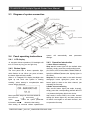
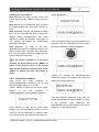
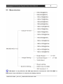
CREATOR CORPORATION(CHINA) CR-iMAX901HD Multi-Signal Scaler User Manual V1.0 Version CREATOR CORPORATION The meaning of symbols ■ Safety instructions For your safe and correct use of equipments, we use a lot of symbols on the equipments and in the manuals, demonstrating the risk of body hurt or possible damage to property for the user or others. Indications and their meanings are as follow. Please make sure to correctly understand these instructions before reading the manual. This is A level product, which may cause radio interference in the living environment. In this case,users may need to take the feasible measures to get around the interference. Remind users that the dangerous voltage without insulation occurring within the equipment may cause people suffer from shock CE certification means that the product has reached the directive safety requirements defined by the European Union. Users can be assured about the use of it SGS certification means that the product has reached the quality inspection standards proposed by the world's largest SGS. This product passed the ISO9001 international quality certification (certification body: TUV Rheinland,Germany). Warning: in order to avoid electrical shock, do not open the machine cover, nor is the useless part allowed to be placed in the box. Please contact the qualified service personnel. ■ General information instructions It lists the factors leading to the unsuccessful operation or set and the relevant information to pay attention to Important note Warning In order to ensure the reliable performance of the equipment and the safety of the user, please observe the following matters during the process of installation, use and maintenance: The matters needing attention of installation ◆ Please do not use this product in the following places:the place of dust,soot and electric conductivity dust, corrosive gas, combustible gas; the place exposed to high temperature, condensation,wind and rain; the occasion of vibration and impact . Electric shock, fire, wrong operation can lead to damage and deterioration to the product, either; ◆In processing the screw holes and wiring, make sure that metal scraps and wire head will not fall into the shaft of controller, as it could cause a fire, fault, or incorrect operation; ◆When the installation work is over, it should be assured there is nothing on the ventilated face, including packaging items like dust paper. Otherwise this may cause a fire, fault, incorrect operation for the cooling is not free; ◆Should avoid wiring and inserting cable plug in charged state, otherwise it is easy to cause the shock, or electrical damage; ◆The installation and wiring should be strong and reliable,contact undesirable may lead to false action; ◆For a serious interference in applications, should choose shield cable as the high frequency signal input or output cable, so as to improve the anti-jamming ability of the system. Attention in the wiring ◆Only after cutting down all external power source, can install, wiring operation begin, or it may cause electric shock or equipment damage; ◆This product grounds by the grounding wires .To avoid electric shocks, grounding wires and the earth must be linked together. Before the connection of input or output terminal, please make sure this product is correctly grounded; ◆Immediately remove all other things after the wiring installation. Please cover the terminals of the products cover before electrification so as to avoid cause electric shock. Matters needing attention during operation and maintenance ◆Please do not touch terminals in a current state,or it may cause a shock, incorrect operation; ◆Please do cleaning and terminal tighten work after turning off the power supply. These operations can lead to electric shock in a current state; ◆Please do the connection or dismantle work of the communication signal cable , the expansion module cable or control unit cable after turning off the power supply, or it may cause damage to the equipment, incorrect operation; ◆Please do not dismantle the equipment, avoid damaging the internal electrical component; ◆Should be sure to read the manual, fully confirm the safety, only after that can do program changes,commissioning,start and stop operation; Matters needing attention in discarding product ◆Electrolytic explosion:the burning of electrolytic capacitor on circuit boards may lead to explosion; ◆Please collect and process according to the classification, do not put into life garbage; ◆Please process it as industrial waste, or according to the local environmental protection regulations. Preface Video Converter User’s Manual mainly introduces the operation methods of CR-iMAX901HD, their main performance parameters and common fault solutions. This manual is only used as user instruction, not for a repair service usage. The functions or related parameters may be changed since the date of issue, please inquire the supplemental information from CREATOR Electronics or local distributors. The copyright of this manual belongs to CREATOR Electronics. Without permission, no unit or individual shall adopt part or all of its content for commercial use. The manual is protected by of the Copyright Law of the People’s Republic of China and other regulations about intellectual property rights. Without written permission shall not be copied or distributed. Contents Chapter One Overview........................................................................................................................................... 1 1.1 Features...................................................................................................................................................1 1.2 Installation............................................................................................................................................... 1 Chapter Two System Introduction.........................................................................................................................2 2.1 Panel instructions...................................................................................................................................2 2.2 Interface description.............................................................................................................................. 3 2.2.1 COM port description................................................................................................................. 3 2.2 RJ45 network cable producing methods............................................................................................4 2.3 Diagram of system connection............................................................................................................ 5 2.4 Panel operating instructions.................................................................................................................5 2.4.1 LCD display................................................................................................................................. 5 2.4.2 Button lights................................................................................................................................. 5 2.4.3 Operation introduction................................................................................................................5 2.4.4 Operation examples................................................................................................................... 6 2.5 Menu structure........................................................................................................................................8 Chapter Three Code Instructions..........................................................................................................................9 Chapter Four Specifications................................................................................................................................ 12 Chapter Five Common Trouble Solution........................................................................................................... 15 CR-iMAX901HD Multiple Signals Scaler User Manual 1 Chapter One Overview New generation of CR-iMAX901HD is a kind of scaler that can switch different types of signal input to HDMI and HDBase output. It has 9 input video signal source: CVBS,(Y,Pb/Cb,Pr/Cr),VGA ,HDMI and HDBaseT signal convert/switch to unified HDMI/HDBaseT signal output,all input signals can fold lines to a user-defined output resolution. The product also supports 9 unbalanced analog stereo audio inputs,by switching to the audio amplifier output. HDMI input and output can support audio signal synthesis or separation. Scaler using the front panel buttons,RS232,IR and Ethernet control and HDBaseT remote control,can be widely used in broadcast television engineering, multimedia conference room, large screen display engineering, television education, command and control centers and other occasions. Port 1.1; HDMI inputs and outputs can isolate or synthesize audio; Support brightness,contrast adjustment, VGA screen automatically adjustment,thus to meet your different needs for image screen visual effects; Support brightness,contrast adjustment,VGA screen automatically adjustment,thus to meet your different needs for image screen visual effects; EDID manager; With the function of restoring factory defaults. 1.2 Installation Matrix host with all-metal chassis can be installed on the standard 19-inch rack,as shown below: 1.1 Features Support 9 video signal input; 1CVBS,1Y,Pb/Cb,Pr/Cr,2VGA,3HDMI, 1DisplayPort, 1HDBaseT input; 2 video signal output; 1 HDMI,1 HDBaseT output; Support 9 analog audio inputs;unbalanced stereo, 20Hz~20KHz; Support 1 balanced stereo audio amplifier output;2x10W @ 8Ω,2x20W@4Ω; Each audio input has 8 degree coarse control of volume,the output has 100 degree fine control of volume; Input and output resolution maximum support WUXGA; Audio and video switching;truly realizing switch with no blank screen, no debris; Support for HDM 1.2a, HDCP1.3,Display CREATOR CHINA 2014-07 WWW.CREATOR1997.COM CR-iMAX901HD Multiple Signals Scaler User Manual 2 Chapter Two System Introduction 2.1 Panel instructions Front panel: Rear panel: LCD display Display the current status of output screen and operating information. you must set the current state of switching the audio through AV. AV button lights, INPUTS SELECTION select the audio input signal. SENSOR——infrared receiver Use with the dedicated remote control of CREATOR. MUTE——normal audio/ silent mode MUTE button light is silent mode, MUTE button lights off is normal mode. INPUTS SELECTION——input source type, input audio channel selection keys It is used to select the input source type.If you need to select VGA1 source signal input, you need to press the corresponding button, similarly, if you need to select 1-10 channel input audio signal source, just press the corresponding button. The silent mode set by the MUTE button 1 2 5 3 4 AV——video/ audio setting button If you need to select the video input signal from the INPUTS SELECTION, you must set the current state of switching the video through AV firstly; if you need to select the audio input signal, CREATOR CHINA 2014-07 is invalid to the DisplayPort interface input audio signal. SETUP MENU——Menu setting button With this button,you can enter the LCD menu to set the corresponding function ENTER——OK The OK button to set the MENU function 6 PARAMETER——check knob Cooperate with MENU settings,to be as a menu direction arrow. 7 WWW.CREATOR1997.COM CR-iMAX901HD Multiple Signals Scaler User Manual MASTER VOL——master volume control knob This knob can help to adjust the analog output volume,each step is 0.5Db. 8 3 synthesis HDIM output. AUDIO INPUTS 4 and VGA2 signal default fixed synthesis HDIM output. CONTROL——signal control district RS-232——RS-232 control port, with the baud rate of 115200,is to connect a computer or other equipment with RS232 control interface to achieve the goal of controlling the device. ETHERNET——Ethernet control port can get into the internet to achieve the goal of controlling the device. 13 AUDIO INPUTS——9 unbalanced audio inputs AUDIO INPUTS1~9 unbalanced audio input interface,wherein when the AUDIO INPUTS 1~4 audio interfaces have access to the audio source,CV,YPbPr,VGA1,VGA2 and other video input interface have access to signals: AUDIO INPUTS 1 and CV signal default fixed synthesis HDIM output. AUDIO INPUTS 2 and YPbPr signal default fixed synthesis HDIM output. AUDIO INPUTS 3 and VGA1 signal default fixed synthesis HDIM output. AUDIO INPUTS 4 and VGA2 signal default fixed synthesis HDIM output. 9 VIDEO INPUTS——1 CVBS, 1 component video YPbPr,2 VGA,3 HDMI,1 DisplayPort,1 HDBaseT input. 10 14 Ground column System power input port Controller power input,support 50/60Hz. 15 AC100~240V 2.2 Interface description 2.2.1 COM port description Professional CR-iMAX901HD switching scaler can control via RS-232 serial interface or optional Ethernet control port. DisplayPort audio interface input signal can not be output from the amplifier balanced audio interface. AMPLIFIER OUTPUT balanced audio output 11 ——1 amplifier COM port pin description is as follows: VIDEO OUTPUT——1 HDMI, 1 HDBaseT output; Wherein when the CV, YPbPr, VGA1,VGA2 video input interface and AUDIO INPUTS 1~4 audio interface have access to signals: AUDIO INPUTS 1 and CV signal default fixed synthesis HDIM output. AUDIO INPUTS 2 and YPbPr signal default fixed synthesis HDIM output. AUDIO INPUTS 3 and VGA1 signal default fixed 12 CREATOR CHINA 2014-07 Pin-out signal 1 - 2 TXD Sending data 3 RXD Receiving data 4 - 5 GND 6 - - 7 - - 8 - - 9 - - WWW.CREATOR1997.COM description - Signal ground CR-iMAX901HD Multiple Signals Scaler User Manual 4 2.2 RJ45 network cable producing methods This system used CAT-5 (five wire) as materials, and installed RJ45 connectors at both ends of CAT-5(commonly known as crystal head),thus to connect the network device.Twisted Pair standard connection provisions is designed to ensure the layout symmetry of the cable connector,thus you can make the interference between the cable connector cancel each other out.General UTP cable has four pairs of thin twisted lines,and marked with different colors.There are two methods of twisted pair connection:EIA/TIA 568B standard and EIA/TIA 568A standard. T568A line order 1 2 3 4 5 6 7 8 White and green green White and orange blue White and blue orange White and brown brown T568B line order 1 2 3 4 5 6 7 8 White and orange orange White and green blue White and blue green White and brown brown Straight-through line:both ends are connected according to T568B standard. Crossover cable:one end is connected according to T568A standard, the other end is connected according to T568B standard. When connected to the network router,we use the straight-though line connection method. When connected to a PC computer control,we use crossover cable connection method. CREATOR CHINA 2014-07 WWW.CREATOR1997.COM CR-iMAX901HD Multiple Signals Scaler User Manual 5 2.3 Diagram of system connection 2.4 Panel operating instructions 2.4.1 automatically save parameter LCD display 10 seconds without operation,LCD backlight will turn off. Press any key,you can light it up. 2.4.2 system will settings. Button lights The front panel has a button operation light, which flashes in red. When you press a button, the button lights will shine inside. When it is charged,LCD display backlight also lights up and show that system is starting Loading…,when startup is completed,the main screen will be displayed. Menu operation steps can be summarized as: Enter the menu select setting select the option parameter information determine the setting After setting 10 seconds without operation,the Option CREATOR CHINA 2014-07 2.4.3 Operation introduction 1,video channel switching Step one:AV button lights off (the default video channel), simply press the corresponding button. (CV,YPbPr,VGA1,VGA2,HDMI1,HDMI2,HDMI3,D isplayPort,HDBaseT)buttons,the lighting lights is the choice. Step two:The current state is the audio channel settings(AV button lights),then press the AV button again to reset to the video channel, just repeating the first step. 2,Audio channel switching Step one:AV button lights (set audio channel), simply press the corresponding (AUDIO INPUTS 1~9) buttons,the lighting light is the choice. Step two:the current state is the video channel setting (AV button lights off), and then press the AV button once again to set audio channel. Just to repeat the first step. WWW.CREATOR1997.COM CR-iMAX901HD Multiple Signals Scaler User’s Manual 用户手册 3,Setting the menu options Step one:press any button to light up the LCD screen,then press the “MENU”to enter the menu option. Step two:turn the PARAMETER knob to select the needed setting item, then press “ENTER” to enter. Step three:after entering the Selecting Setting Item, turn the PARAMETER knob to select the desired setting parameters,and then press “ENTER”to confirm the selection. Each press of LCD screen,it will display the corresponding parameter information. Step four:when you need to set many parameters,just press the “MENU”to return to the previous menu after confirming each parameter, then you just need to repeat the operation of the second, third and fourth steps. 6 1920X1080@50Hz. 3.The LCD display shows the current status of the option,then turn the PARAMETER knob to select the desired parameter 1280X1024@60Hz. If the current operation is in the menu structure (as shown below), press “MENU” to return to the previous menu. If the current state is audio and video channel switch, press “MENU” to display the main menu page of scaler. 2.4.4 Operation examples Such as:set the output resolution to 1280X1024@60Hz,the brightness to 60 and adjust the output volume to + 10.5dB. 1.Press “MENU” to enter into the menu option settings to set the resolution to 1280X1024@60Hz, LCD will display as follows: Press “ENTER” to enter into the menu option settings, turn the PARAMETER knob to set the “OUTPUT Format”parameter. For example: when you enter the menu, the resolution will display as CREATOR CHINA 2014-07 4.When you selected the parameters,press “ENTER”to confirm the changes,LCD screen will display the setting parameters. 5.Set the brightness parameter to 60. After you setting the resolution,press the “MENU” to return to the previous menu option,turn the PARAMETER knob to select until the LCD screen display the “Image Setting” option. WWW.CREATOR1997.COM CR-iMAX901HD Multiple Signals Scaler User’s Manual 用户手册 7 9.Adjust the output volume to+10.5dB, then turn the MASTER VOL knob until the LCD displays the parameters to + 10.5dB, thus the operation is completed. 6.Press“ENTER”to enter the menu option settings,turn the PARAMETER knob to select until the LCD screen displays the “Bright Adjust” option. 7.Press “ENTER” to confirm the option, thus to enter the option parameter settings. Now the LCD screen shows the current status of the option, then use “PARAMETER” to set the parameter to “60”. 8.Press“ENTER” to confirm the changes, then the LCD screen will display the parameter information that has been set successfully. CREATOR CHINA 2014-07 WWW.CREATOR1997.COM CR-iMAX901HD Multiple Signals Scaler User’s Manual 用户手册 8 2.5 Menu structure “VGA Adjust” is only valid when the VGA input channel is inserted; the “COPY TO HDMI” in EDID menu is only valid when it is inserted to the display terminal. CREATOR CHINA 2014-07 WWW.CREATOR1997.COM 9 CR-iMAX901HD Multiple Signals Scaler User’s Manual Chapter Three Code Instructions Serial protocol:Baud rate:115200 Data bits:8 Stop bits:1 Ethernet:Agreement :TCP,IP:192.168.1.190 PORT:6666 Video Switch Command Parity bit:none Command Response Description S SOURCE 0. >SOURCE CV CV INPUT S SOURCE 1. >SOURCE YPbPr YPbPr INPUT S SOURCE 2. >SOURCE VGA1 VGA1 INPUT S SOURCE 3. >SOURCE VGA2 VGA2 INPUT S SOURCE 4. >SOURCE HDMI1 HDMI1 INPUT S SOURCE 5. >SOURCE HDMI2 HDMI2 INPUT S SOURCE 6. >SOURCE HDMI3 HDMI3 INPUT S SOURCE 7. >SOURCE DisplayPort DisplayPort INPUT S SOURCE 8. >SOURCE HDBaseT HDBaseT INPUT R SOURCE. >Video Input: YPbPr Read Current Video input Command Response Description S AUDIO 0. >AUDIO 1 INPUT AUDIO 1 INPUT S AUDIO 1. >AUDIO 2 INPUT AUDIO 2 INPUT S AUDIO 2. >AUDIO 3 INPUT AUDIO 3 INPUT S AUDIO 3. >AUDIO 4 INPUT AUDIO 4 INPUT S AUDIO 4. >AUDIO 5 INPUT AUDIO 5 INPUT S AUDIO 5. >AUDIO 6 INPUT AUDIO 6 INPUT S AUDIO 6. >AUDIO 7 INPUT AUDIO 7 INPUT S AUDIO 7. >AUDIO 8 INPUT AUDIO 8 INPUT S AUDIO 8. >AUDIO 9 INPUT AUDIO 9 INPUT S AUDIO 9. >HDMI&HDBaseT AUDIO INPUT HDMI&HDBaseT Audio Input for Video is HDMI&HDBaseT R AUDIO. >Audio Input: AudioAnalog 1 Read Current Audio Input Audio Switch Command Resolution Command Command Response S OUTPUT 0! >OUTPUT 640x480@60Hz Resolution Output 640x480@60Hz S OUTPUT 1! >OUTPUT 800x600@60Hz Resolution Output 800x600@60Hz S OUTPUT 2! >OUTPUT 1024x768@60Hz Resolution Output 1024x768@60Hz S OUTPUT 3! >OUTPUT 1280x720@60Hz Resolution Output 1280x720@60Hz S OUTPUT 4! >OUTPUT 1280x800@60Hz Resolution Output 1280x800@60Hz S OUTPUT 5! >OUTPUT 1280x960@60Hz Resolution Output 1280x960@60Hz S OUTPUT 6! >OUTPUT 1280x1024@60Hz Resolution Output 1280x1024@60Hz CREATOR CHINA 2014-07 WWW.CREATOR1997.COM Description 10 CR-iMAX901HD Multiple Signals Scaler User’s Manual S OUTPUT 7! >OUTPUT 1360x768@60Hz Resolution Output 1360x768@60Hz S OUTPUT 8! >OUTPUT 1366x768@60Hz Resolution Output 1366x768@60Hz S OUTPUT 9! >OUTPUT 1400x1050@60Hz Resolution Output 1400x1050@60Hz S OUTPUT A! >OUTPUT 1440x900@60Hz Resolution Output 1440x900@60Hz S OUTPUT B! >OUTPUT 1600x1200@60Hz Resolution Output 1600x1200@60Hz S OUTPUT C! >OUTPUT 1680x1050@60Hz Resolution Output 1680x1050@60Hz S OUTPUT D! >OUTPUT 1920x1080@50Hz Resolution Output 1920x1080@50Hz S OUTPUT E! >OUTPUT 1920x1080@60Hz Resolution Output 1920x1080@60Hz S OUTPUT F! >OUTPUT 1920x1200@60Hz Resolution Output 1920x1200@60Hz R OUTPUT! >Output Resolution: 800x600@60Hz Read Current Output Format Audio Input Volume Adjust Command Command Response Description A [X] INPUT 0% >AUDIAO INPUT [X+1] 0dB Audio Input [x] setting 0dB A [X] INPUT 1% >AUDIAO INPUT [X+1] -3dB Audio Input [x] setting -3dB A [X] INPUT 2% >AUDIAO INPUT [X+1] -6dB Audio Input [x] setting -6dB A [X] INPUT 3% >AUDIAO INPUT [X+1] -9dB Audio Input [x] setting -9dB A [X] INPUT 4% >AUDIAO INPUT [X+1] -12dB Audio Input [x] setting -12dB A [X] INPUT 5% >AUDIAO INPUT [X] -15dB Audio Input [x] setting -15dB A [X] INPUT 6% >AUDIAO INPUT [X] -18dB Audio Input [x] setting -18dB A [X] INPUT 7% >AUDIAO INPUT [X] -21dB Audio Input [x] setting -21dB [X] represents the which audio to input. When the [X] is 9, it means that the audio inputs is HDMI1, HMDI2, HDMI3 and HDBaseT. For example: The second input audio is adjusted -12dB, its command is as follows: A 1 INPUT 4% Audio Output Volume Adjust Command Command Response Description A+ OUTPUT% >Analog AUDIAO OUTPUT + 0.5dB Analog Audio Output setting + 0.5dB A- OUTPUT% >Analog AUDIAO OUTPUT - 0.5dB Analog Audio Output setting - 0.5dB B+ OUTPUT% >HDMI AUDIAO OUTPUT + 0.5dB HDMI Audio Output setting + 0.5dB B- OUTPUT% >HDMI AUDIAO OUTPUT - 0.5dB HDMI Audio Output setting - 0.5dB MUTE ON% >MUTE ON Audio Output Mute On MUTE OFF% >MUTE OFF Audio Output Mute Off CLOSE 0% >Analog AUDIO MUTE ON Analog Audio MUTE ON OPEN 0% >Analog AUDIO MUTE OFF Analog Audio MUTE OFF CLOSE 1% >HDMI AUDIO MUTE ON HDMI Audio MUTE ON OPEN 1% >HDMI AUDIO MUTE OFF HDMI Audio MUTE OFF CREATOR CHINA 2014-07 WWW.CREATOR1997.COM 11 CR-iMAX901HD Multiple Signals Scaler User’s Manual Image adjustment commands Command Response Description Auto Adjust* >VGA Input Auto Adjust VGA Image auto adjust VStart+* >VGA Input V Start + 1 Move the VGA input image one column up VStart-* >VGA Input V Start - 1 Move the VGA input image one column down HStart+* >VGA Input H Start + 1 Move the VGA input image one column left HStart-* >VGA Input H Start - 1 Move the VGA input image one column right HTotal+* >VGA Input H Total + 1 Add 1 column to the total of VGA input images HTotal-* >VGA Input H Total - 1 Remove 1 column of the total of VGA input images Brightness 000* >Brightness Value: 000 Set Brightness Brightness* >Brightness Value: 000 Read Brightness Contrast 000* >Contrast Value: 000 Set Contrast Contrast* >Contrast Value: 000 Read Contrast Other commands Command Response Description <DEFAULT> >DEFAULT OK Restore factory defaults in next charge <COPYEDID> >COPY EDID OK Copy EDID display device to HDMI interface <SIPR[192-168-1-190]> >SIPR:192.168.1.190 Set the IP address <GAR[192-168-1-1]> >GAR:192.168.1.1 Set the gateway address <SUBR[255-255-255-0]> >SUBR:255.255.255.0 Set the subnet source address <SPORT[6666]> >SPORT:6666 Set the port number <SIPR> >SIPR:192.168.1.190 Query the IP address <GAR> >GAR:192.168.1.1 Query the gateway address <SUBR> >SUBR:255.255.255.0 Query the subnet mask <SPORT> >SPORT:6666 Query the port number <BellOn> >Bell On Open the buzzer <BellOff> >Bell Off Close the buzzer <BellStatus> >Bell Status: ON Query buzzer status <SW> >LPMCU SW Versions: V1.0 >FPMCU SW Versions: V1.0 >FLMCU SW Versions: V1.0 Check the software version CREATOR CHINA 2014-07 WWW.CREATOR1997.COM CR-iMAX901HD Multiple Signals Scaler User Manual 12 Chapter Four Specifications model Technical Specifications CR-iMAX901HD Analog CV video/YPbPr video Gain 0dB Bandwidth 150MHz @ -3dB Format NTSC,PAL,SECAM Differential error phase 0.1°,3.58-4.43 MHz Differential gain error 0.1%,3.58-4.43 MHz Switching speed 200 ns(the maximum time) Signal type Composite video(CVBS), Component video(YPbPr/YCbCr) Interface RCA female joint(4PIN),1(CVBS),1(YPbPr/YCbCr) Minimum / maximum Analog signal: -2V/+2V level Impedance 75 Ω Return loss <-30dB@5MHz Analog VGA video Gain 0 dB Bandwidth 380 MHz Signal type VGA Interface 15-pin HD female interface,2 VGA input Signal strength 0.63V p-p to 0.9 V p-p Impedance 75 Ω Return loss <-40dB@5MHz DC compensation Maximum ±5mV Supported resolution 640x480@60Hz;800x600@60Hz;1024x768@60Hz;1280x720@60Hz;1280x 800@60Hz;1280x960@60Hz;1280x1024@60Hz;1360x768@60Hz;1366x76 8@60Hz;1400x1050@60Hz;1440x900@60Hz;1600x1200@60Hz;1680x105 0@60Hz;1920x1080@50Hz;1920x1080@60Hz;1920x1200@60Hz HDMI video Supported protocols HDMI1.3a,DVI1.0,HDCP1.3 Maximum pixel clock 225MHz Interface bandwidth 6.75Gbps(RGB:2.25 Gbps/per lane) Signal type In HDMI 1.3a / DVI 1.0 specifications HDMI / DVI-D all-digital T.M.D.S. signal Interface HDMI-A interface (Type A connector ),3 HDMI input,1HDMI output Minimum / maximum T.M.D.S.2.9V/3.3V level CREATOR CHINA 2014-07 WWW.CREATOR1997.COM CR-iMAX901HD Multiple Signals Scaler User Manual 13 Impedance 100 Ω Input EDID Use the system default EDID,( Supports EDID mapped to the input terminal) The maximum bias error DC 15mV Recommended maximum input distance The input distance is less than 25 meters;output less than 10 meters,in 1920x1080p@60(you’re recommended to use the certified HDMI dedicated wire, such as the Molex TM wire.) Supported resolution 640x480@60Hz;800x600@60Hz;1024x768@60Hz;1280x720@60Hz;1280x 800@60Hz;1280x960@60Hz;1280x1024@60Hz;1360x768@60Hz;1366x76 8@60Hz;1400x1050@60Hz;1440x900@60Hz;1600x1200@60Hz;1680x105 0@60Hz;1920x1080@50Hz;1920x1080@60Hz;1920x1200@60Hz DisplayPort video Interface 20-pin DP interface, standard,1 DisplayPort input Supported protocols DisplayPort 1.1 Maximum transmission delay 500us Transmission bandwidth The maximum of transmission bandwidth is 10.8Gb/S Supported resolution 640x480@60Hz;800x600@60Hz;1024x768@60Hz;1280x720@60Hz;1280x 800@60Hz;1280x960@60Hz;1280x1024@60Hz;1360x768@60Hz;1366x76 8@60Hz;1400x1050@60Hz;1440x900@60Hz;1600x1200@60Hz;1680x105 0@60Hz;1920x1080@50Hz;1920x1080@60Hz;1920x1200@60Hz HDBaseT video Interface RJ-45 female interface;1 HDBaseT input,1 HDBaseT output Supported protocols Conform to HDCP standard Maximum pixel clock 225MHz Impedance 100Ω Recommended maximum input distance The maximum transmission distance is ≤100m(use standard Cat5 enhanced or Cat6 cable) Supported resolution 640x480@60Hz;800x600@60Hz;1024x768@60Hz;1280x720@60Hz;1280x 800@60Hz;1280x960@60Hz;1280x1024@60Hz;1360x768@60Hz;1366x76 8@60Hz;1400x1050@60Hz;1440x900@60Hz;1600x1200@60Hz;1680x105 0@60Hz;1920x1080@50Hz;1920x1080@60Hz;1920x1200@60Hz Audio signal Input/output interface 9 3-pin phoenix joint/each has unbalanced audio input,Balanced audio amplifier output of 1 4-pin phoenix joint Gain 0 dB Frequency response 20 Hz~20 kHz, THD + Noise 0.05%@1 kHz (with rated voltage) Signal-to-Noise(S/N ) >80dB Stereo separation >80dB@1 kHz CREATOR CHINA 2014-07 WWW.CREATOR1997.COM CR-iMAX901HD Multiple Signals Scaler User Manual Common-mode rejection ratio(CMRR) >75dB@:20 Hz ~ 20 kHz Signal type stereo Impedance input:>10 kΩ(Unbalanced) maximum input level +19.5dBu, Gain error ±0.1dB @ 20 Hz ~ 20 kHz Control types button Front panel, LCD screen status display serial control interface RS-232,9-pin female D-type interface Baud rate and protocol Baud rate:115200,Data bits:8 bits,stop bits:1,No parity The serial control port 2=TX,3=RX,5=GND structure Ethernet interface control Ethernet protocol control RJ-45 female interface TCP/IP Ethernet control rate Adaptive 10M/100M,full-duplex or half-duplex HDBaseT remote HDBaseT remote RS232 control Specification Power supply 100VAC~240VAC,50/60Hz Temperature Storage and operation temperature:-20°~+70°C Humidity Storage and operation humidity:0 ~.95% Chassis Size 483(L)X230(W)X44mm(H) Product weight About 2.3kg MTBF 30,000 hours Warranty 1 year free warranty and lifetime maintenance CREATOR CHINA 2014-07 WWW.CREATOR1997.COM 14 CR-iMAX901HD Multiple Signals Scaler User Manual 15 Chapter Five Common Trouble Solution Trouble Phenomenon Troubleshooting methods May be the VGA signal lines on both ends of the joint are not well connected or the wires has open circuit or short circuit. Check whether the communication port of the control software is corresponding to the serial of the connected equipment, whether the communication port of the computer is good,whether the communication protocol is correct. When switching CR-iMAX901HD,there is return code but no corresponding image output Check whether the corresponding input end has signal or not (you can use oscilloscope or multimeter to test),if there is no signal, maybe the input wire is loose or broken, just to replace the connection cable. If the POWER light is not bright and the LCD has no display and the operation has no response Check whether the power input is good or not. It is possible that the input and output line are not connected well or there is no well-grounded. It is possible that the power of the device is not well grounded. Please follow the correct way to ground,otherwise it is easy to damage the host and shorten the life of the it. It is possible that the audio or video interface is loose,just replace it. When the color is missing or no video signal output appears When a serial port (generally refers to:computer serial port) can not control CR-iMAX901HD matrix If the image output has been jammed If you can feel significant static electricity when you pull and plug audio and video interface If the LCD display is normal,the communication port has return code,but there is no image output or audio output If the panel buttons and the communication ports of CR-iMAX901HD can not be controlled CREATOR CHINA 2014-07 It is possible that there is a short in the wire, just replace it. It is possible that the circuit is broken,just replace it. It is possible that the inside pieces of the host has been damaged.Please send it to the professionals to repair. WWW.CREATOR1997.COM CREATOR CORPORATION(CHINA) Copyright by CREATOR Last Revision:07/2014