1
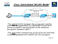
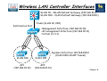
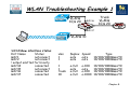
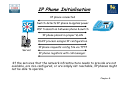
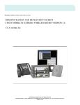
Chapter 8 – Troubleshooting Converged
Networks
Objectives
• Explain the operation of the Cisco Centralised
Wireless model.
• Describe LWAPP operation & troubleshooting
techniques.
• Explain the requirement for QoS converged
networks.
• Describe basic QoS operation & troubleshooting
techniques.
• Describe basic multicast operation &
troubleshooting techniques.
Chapter 8
Autonomous or Lightweight?
• Most Cisco wireless access points/bridges are available
as autonomous or lightweight devices.
• Lightweight APs (LWAP) use Lightweight Access Point
Protocol (LWAPP) and must have a Wireless LAN
Controller (WLC) to function within the network.
• Most Cisco
autonomous APs can
be software upgraded
to function as
lightweight APs.
Chapter 8
Cisco Unified Wireless Network
Unified Advanced Services
•Unified cellular and Wi-Fi VoIP. Advanced
threat detection, identity networking, locationbased security, asset tracking and guest access.
World-Class Network Management
•Same level of security, scalability, reliability,
ease of deployment, and management for wireless
LANs as wired LANs.
Network Unification
Integration into all major switching and routing
platforms. Secure innovative WLAN controllers.
Mobility Platform
Ubiquitous network access in all environments.
Enhanced productivity. Proven platform with large
install base and 63% market share. Plug and Play.
Client Devices
90% of Wi-Fi silicon is Cisco Compatible
Certified. “Out-of-the-Box” wireless security.
Chapter 8
Cisco Centralized WLAN Model
Switched/Routed Wired
Network
LWAPP Tunnel
Data & Control
Trunk
•The control traffic between the access point and the
controller is encapsulated by Lightweight Access Point
Protocol (LWAPP), and encrypted via the Advanced
Encryption Standard (AES).
•The data traffic between the access point and controller
is also encapsulated with LWAPP, but not encrypted.
Chapter 8
Wireless LAN Controller Interfaces
•VLAN 10 – WLAN Default Gateway (192.168.10.1)
•VLAN 100 – VLAN Default Gateway (192.168.100.1)
Distribution Port
Trunk (VLAN 10, 100)
•Management Interface (192.168.10.10)
•AP management Interface (192.168.10.11)
•Virtual (1.1.1.1)
Dynamic Interface 192.168.100.2
(VLAN 100 LWAPP Tunnel)
VLAN 100
AP1
(192.168.10.12)
VLAN 100
AP2
(192.168.10.13)
Chapter 8
Wired Network Issues Impacting on
WLANs
• Many issues that might be perceived as wireless problems result from
underlying issues on the wired network:
• PoE - WAPs are often installed away from power outlets, and require
Power over Ethernet (PoE) to provide a 48vdc supply over their data
connection.
• VLANs - wireless users might experience connectivity issues if traffic
from their wireless VLAN is not permitted over a trunk in the wired
network.
• Security - UDP ports 12222 and 12223 are used by LWAPP and should be
permitted between a WAP and a WLC.
• DHCP – WLANs rely on DHCP to provide roaming clients with IP
addresses.
• QoS -Latency-sensitive traffic traveling over a wireless network might
suffer from poor performance if QoS markings are not preserved as
traffic crosses the boundary between the wireless and wired portions of
a network.
Chapter 8
WLAN Troubleshooting Example 1
VLANs
10,& 20
Gi0/36
Trunk
VLANs
10,& 20
R1
Gi0/37
VLANs 10
•Wireless services have suddenly stopped; clients are not able to
associate to the AP. Even from the wired PCs that are used for
troubleshooting, it is not possible to connect to the AP or the WLC, using
either SSH or HTTPS
SW1#show cdp neighbors
Capability Codes: R - Router, T - Trans Bridge, B - Source Route Bridge
S - Switch, H - Host, I - IGMP, r - Repeater, P - Phone
Device ID
Local Intrfce Holdtme
Capability
Platform Port ID
ap
Gig 0/37
128
TI
AIR-LAP125 Gig 0
521-8
Gig 0/39
135
AIR-LAP521 Fas 0
521-7
Gig 0/34
122
AIR-LAP521 Fas 0
Cisco_9a:8c:e0
Gig 0/36
175
H
AIR-WLC210 Unit - 0 Slot – 0 Port - 1
Chapter 8
WLAN Troubleshooting Example 1
VLANs
10,& 20
Gi0/36
Trunk
VLANs
10,& 20
R1
Gi0/37
VLANs 10
SW1#show interface status
Port Name
Status
Gi0/1
notconnect
Gi0/2
notconnect
! output omitted for brevity
Gi0/34
connected
Gi0/35
notconnect
Gi0/36
connected
Gi0/37
connected
vlan
1
1
Duplex Speed
auto
auto
auto
auto
Type
10/100/1000BaseTX
10/100/1000BaseTX
1
1
trunk
10
a-full
auto
a-full
a-full
10/100/1000BaseTX
10/100/1000BaseTX
10/100/1000BaseTX
10/100/1000BaseTX
a-100
auto
a-100
a-1000
Chapter 8
WLAN Troubleshooting Example 1
VLANs
10,& 20
Gi0/36
Trunk
VLANs
10,& 20
R1
Gi0/37
VLANs 10
SW1#show interfaces switchport | begin 0/36
Name: Gi0/36
Switchport: Enabled
Administrative Mode: trunk
Operational Mode: trunk
Administrative Trunking Encapsulation: dot1q
Operational Trunking Encapsulation: dot1q
Negotiation of Trunking: On
! output omitted for brevity
Trunking VLANs Enabled: 1
SW1(config)#int g0/36
SW1(config-if)#switchport trunk allowed vlan add 10,20
SW1(config-if)#end
Chapter 8
WLAN Troubleshooting Example 2
VLANs
10,& 20
Gi0/36
Trunk
VLANs
10,& 20
R1
Gi0/37
VLANs 10
•Wireless services are now available, but wireless users are still
experiencing performance issues, especially with VoIP traffic.
SW1#show mls qos int g0/37
GigabitEthernet0/34
trust state: not trusted
trust mode: not trusted
trust enabled flag: ena
COS override: dis
default COS: 0
DSCP Mutation Map: Default DSCP
Mutation Map
Trust device: None
qos mode: port-based
•A trust boundary is the point within
the network where QoS markings
such as DSCP are first accepted.
•By default, switch ports will reset
DSCP values unless you explicitly tell
the port to trust those values.
Chapter 8
WLAN Troubleshooting Example 2
VLANs
10,& 20
Gi0/36
Trunk
VLANs
10,& 20
R1
Gi0/37
VLANs 10
SW1(config)#int g0/34
SW1(config-if)#mls qos trust dscp
SW1(config-if)#end
SW1#end
SW1#
SW1#show mls qos int g0/34
GigabitEthernet0/34
trust state: trust dscp
trust mode: trust dscp
trust enabled flag: ena
COS override: dis
default COS: 0
DSCP Mutation Map: Default DSCP
Mutation Map
Trust device: None
qos mode: port-based
Chapter 8
Converged Network Realities
• Traditional data traffic
characteristics:
• Bursty data flow
• FIFO access
• Not overly time-sensitive;
delays OK
• Brief outages are
survivable
• Converged network
realities:
• Constant small-packet voice
flow competes with bursty
data flow.
• Critical traffic must have
priority.
• Voice and video are timesensitive.
• Brief outages are not
acceptable.
Chapter 8
Unified Communications Design
Considerations - Voice
• The following list summarizes the design considerations
of integrating unified communications into a campus:
• Quality of Service: Bandwidth, delay, jitter, packet loss,
Network QoS Readiness, Trust Boundaries, Switch QoS.
• High Availability: STP/RSTP, HSRP/GLBP/VRRP.
• Security: Traffic Segregation (Voice versus Data VLANs),
Firewalling/Filtering.
• Provisioning and Management: PoE, DHCP, TFTP, NTP,
CDP, Trunking, VLANs.
Chapter 8
IP Phone Initialisation
IP phone connected
Switch detects IP phone & applies power
CDP transaction between phone & switch
IP phone placed in proper VLAN
DHCP process assigns IP configuration
TFTP
Server
IP phone requests config file via TFTP
IP phone registers with call manager
•If the services that the network infrastructure needs to provide are not
available, are mis-configured, or are simply not reachable, IP phones might
not be able to operate.
Chapter 8
IP Phone VLAN Considerations
802.1q
Encapsulation
Fa0/11
Voice VLAN
110
Data VLAN 10
SW1(config)#int fa0/11
SW1(config-if)#switchport mode access
SW1(config-if)#switchport voice vlan 110
SW1(config-if)#switchport access vlan 10
•The link mode between the IP phone and the switch is negotiated; the
switch instructs the phone to use a special-case 802.1Q trunk or a single
VLAN access link.
•With a trunk, the voice traffic can be isolated from other user data,
providing security and QoS capabilities.
•To configure the IP phone uplink, configure the switch port where it
connects. The switch port does not need any special trunking configuration
commands if a trunk is wanted.
•If an 802.1Q trunk is needed, a special-case trunk is automatically
negotiated by DTP and CDP.
Chapter 8
Modular QoS CLI Components
Chapter 8
Step 1: Creating Class Maps
256kbps
Data Stream
Fa0/0
R1
S0/0
S0/0
R2
R1(config)# access-list 101 permit tcp any any eq 22
R1(config)# access-list 102 permit tcp any any eq 80
R1(config)# class-map match any class1
R1(config-cmap)# match access-group 101
R1(config-cmap)# exit
R1(config)# class-map match any class2
R1(config-cmap)# match access-group 102
R1(config-cmap)# exit
R1(config)# class-map match any noip
R1(config-cmap)# match not protocol ip
R1(config-cmap)# exit
Chapter 8
Step 2: Creating Policy Maps
256kbps
Data Stream
Fa0/0
R1
S0/0
S0/0
R1(config)# policy-map policy1
R1(config-pmap)# class class1
R1(config-pmap-c)# bandwidth 100
R1(config-pmap-c)# queue-limit 30
R1(config-pmap)# exit
R1(config-pmap)# class class2
R1(config-pmap-c)# bandwidth 80
R1(config-pmap)# exit
R2
Nested Policy:
R1(config)# policy-map 1
R1(config-pmap)# class class1
R1(config-pmap-c)# bandwidth 50
R1(config-pmap-c)# class2
R1(config-pmap-c)# bandwidth 40
R1(config)# policy-map 2
R1(config-pmap)# class classdefault
R1(config-pmap-c)# shape average
128000
R1(config-pmap-c)# service-policy 1
Chapter 8
Step 3: Apply Service Policy
256kbps
Data Stream
Fa0/0
R1
S0/0
S0/0
R2
R1(config)# interface s0/0
R1(config-if)# service-policy output policy1
R1(config-if)# exit
•Although you can assign the same traffic policy to multiple
interfaces, each interface can have only one traffic policy attached
at the input and only one traffic policy attached at the output.
Chapter 8
Basic Verification Commands
R1# show class-map
Class Map match-any class-default (id 0)
Match any
Class Map match-all MUSIC (id 2) R1# show policy-map
Match protocol kazaa2
Policy Map TSHOOT-EXAMPLE
Class EMAIL
Class Map match-any EMAIL (id 1) Bandwidth 128 (kbps) Max Threshold 64
Match protocol pop3
(packets)
Match protocol imap
Match protocol smtp
Class MUSIC
police cir 32000 bc 1500
Class Map match-all VOICE (id 3) conform-action transmit
Match protocol rtp audio
exceed-action drop
Class VOICE
Strict Priority
Bandwidth 256 (kbps) Burst 6400 (Bytes)
Chapter 8
Basic Verification Commands
R1# show policy-map interface serial0/1
Serial0/1
Service-policy output: TSHOOT-EXAMPLE
Class-map: EMAIL (match-any)
0 packets, 0 bytes
5 minute offered rate 0 bps, drop rate 0 bps
Match: protocol pop3
0 packets, 0 bytes
5 minute rate 0 bps
Match: protocol imap
0 packets, 0 bytes
5 minute rate 0 bps
Match: protocol smtp
0 packets, 0 bytes
5 minute rate 0 bps
Queueing
Output Queue: Conversation 265
Bandwidth 128 (kbps) Max Threshold 64
(packets)
(pkts matched/bytes matched) 0/0
(depth/total drops/no-buffer drops) 0/0/0
Chapter 8
Unified Communications Design
Considerations - Video
•Like voice traffic, video traffic is latency-sensitive. Therefore, many of
the same design and troubleshooting considerations for voice traffic (for
example, QoS considerations) also apply to video traffic.
Chapter 8
Unified Communications Design
Considerations - Video
• Due to the bandwidth-intensive and latency-sensitive nature
of video, consider the following when designing or
troubleshooting a video network:
• QoS: Like voice, video packets need to be allocated an appropriate
amount of bandwidth and be treated with high priority.
• Availability: Also like voice, video networks should be built on an
underlying data network with reliable components and redundancy.
• Security: Appropriate security measures, such as encryption and
authentication, should be in place in a video network.
• Multicasting: Multicasting allows a multicast server to send traffic
(for example, a video stream) to a destination Class D IP address known
as a multicast group.
Chapter 8
Unicast vs. Multicast
Unicast
•Sender has to send the
same data flow to each
receiver separately.
Sender
•The sender has to make
copies of the same
packet and send them
once for each receiver.
Multicast
Sender
Access control and threat management mechanisms need to
consider the various protocols and traffic flows that result
from a video-enabled network, e.g. SIP, H.323, SCCP (Skinny),
RTP, RTCP
•Data packets are sent to
multiple receivers - the
packets are not
duplicated for every
receiver but are sent in a
single stream.
•Downstream routers
perform packet
multiplication over
receiving links when
necessary
Chapter 8
IP Multicast Address Structure
IP group addresses:
• Class D address (high-order three bits are set)
• Range from 224.0.0.0 through 239.255.255.255
•Local scope addresses
224.0.0.0 to 224.0.0.255
•Global scope addresses
224.0.1.0 to 238.255.255.255
•Administratively scoped addresses
239.0.0.0 to 239.255.255.255
Chapter 8
IANA Ethernet MAC Address Range
• Normally, network interface cards (NICs) on a LAN segment only
receive packets destined for their burned-in MAC address. However,
there is no Address Resolution Protocol (ARP) equivalent for
multicast address mapping.
• IANA has set aside the vendor code portion of the reserved
Organizationally Unique Identifier (OUI) value to identify multicast
MAC addresses.
• Multicast MAC addresses always begin with the low-order bit (0x01)
in the first octet. Specifically, the 0x01005e prefix (plus the next
lower bit, which is zero) has been reserved for mapping Layer 3 IP
multicast addresses into Layer 2 MAC addresses.
• The complete multicast MAC address range is from 0100.5e00.0000
through 0100.5e7f.ffff.
Fixed
Variable
00000001.00000000.01011110.00000000.00000000.00000000
00000001.00000000.01011110.01111111. 1111111. 11111111
Chapter 8
IP Multicast to MAC Multicast
Mapping
•The translation between IP multicast and MAC address is achieved by the
mapping of the low-order 23 bits of the IP (Layer 3) multicast address into
the low-order 23 bits of the IEEE (Layer 2) MAC address.
224.1.0.1
0 0 0 0 0 0 0 0 0 0 01 0 0 0 0 0 0 0 0 0 0 0 0 0 0 0 1
0 0 0 0 0 01 0 0 0 0 0 0 0 0 0 0 0 0 0 0 0 1
0100.5e01.0001
Chapter 8
IANA Ethernet MAC Address Range
• This gives the possibility that 32 different multicast IP addresses
could all correspond to a single multicast MAC address:
11100000.00000001.00000000.00000001 = 224.1.0.1
11101111.00000001.00000000.00000001 = 239.1.0.1
11100000.10000001.00000000.00000001 = 224.129.0.1
11101111.10000001.00000000.00000001 = 239.129.0.1
Chapter 8
How are Multicast Addresses
Assigned?
Static Global Group Address Assignment:
• Temporary method to meet immediate needs
• Group range: 233.0.0.0 – 233.255.255.255
•Your AS number is inserted in middle two octets
•Remaining low-order octet used for group assignment
• Defined in RFC 2770
•“GLOP Addressing in 233/8”
• Manual address allocation by the admin is still the
most common practice.
Chapter 8
Multicast Protocols
PIM
Host
PIM
Sender
Host
PIM
PIM
Host
IGMP
• There are two main protocols involved in a multicast enabled:
• Routers will run a multicast routing protocol, typically Protocol
Independent Multicast (PIM) whose main role is to advertise the
location of multicast receivers.
• The second main component is the way hosts subscribe to groups, and
announce themselves as members of the group, which is typically
done using Internet Group Management Protocol (IGMP).
Chapter 8
Internet Group Management
Protocol (IGMP)
• How hosts tell routers about group membership.
• Routers solicit group membership from directly connected
hosts.
•RFC 1112 specifies IGMPv1
• Supported on Windows 95
•RFC 2236 specifies IGMPv2
•Supported on latest service pack for Windows and
most UNIX systems
•RFC 3376 specifies IGMPv3
•Supported in Window XP and various UNIX systems
Chapter 8
IGMPv2 Operation
Report
224.1.1.1
H1
1.1.1.10
H2
1.1.1.11
Leave
224.1.1.1
Group 224.1.1.1
H3
1.1.1.12
Join
224.1.1.1
RA
•Members joining a multicast group do not
have to wait for a query to join. They
send an unsolicited report indicating their
interest.
•RA hears the leave message and sends a
group-specific query to see if any other
group members are present. H3 has not
left the multicast group 224.1.1.1 yet, so
it responds with a report message.
Query
224.1.1.1
When H3 leaves, RA again queries the
group. Because host H3 was the last
remaining member of the multicast group
224.1.1.1, no IGMP membership report
for group 224.1.1.1 is received, and the
group times out.
Chapter 8
IGMP Snooping
Member
•Switches become IGMP-aware.
H1
1.1.1.10
H2
1.1.1.11
H3
1.1.1.12
IGMP
Join
0100.5e01.0101
Group 224.1.1.1
0100.5e01.0101
RA
•IGMP packets are intercepted by
the CPU or by special hardware
ASICs.
•Switch examines contents of IGMP
messages to learn which ports want
what traffic.
•Must process all Layer 2 multicast
packets.
•Administration load increased with
multicast traffic load.
S1(config)# ip igmp snooping
S1(config)# ip igmp snooping vlan 10
Chapter 8
Verify Group State
R1#show ip igmp interface
Serial0/0/0 is up, line protocol is up
Internet address is 10.23.23.2/24
IGMP is enabled on interface
Current IGMP host version is 2
Current IGMP router version is 2
IGMP query interval is 60 seconds
IGMP querier timeout is 120 seconds
IGMP max query response time is 10 seconds
Last member query count is 2
Last member query response interval is 1000 ms
Inbound IGMP access group is not set
IGMP activity: 1 joins, 0 leaves
Multicast routing is enabled on interface
Multicast TTL threshold is 0
IGMP querying router is 0.0.0.0 (this system)
Multicast groups joined by this system (number of users):
224.0.1.40(1)
Chapter 8
Multicast Routing Protocols –
Source Distribution Tree
Source 1
IP = 10.1.0.1
Group = 224.1.1.1
A
B
C
Receiver 1
Source 2
IP = 10.2.0.1
Group = 224.2.2.2
D
E
Receiver 2
Notation: (S,G) Notation: (S,G)
S = 10.1.0.1
S = 10.2.0.1
G = 224.1.1.1 G = 224.2.2.2
F
•With a source tree, a separate
tree is built for each source to
all members of its group.
•Because the source tree takes
the shortest path from the
source to its receivers, it is also
called a shortest path tree
(SPT).
Notation: (S,G)
S = Source
G = Group
Chapter 8
Multicast Routing Protocols –
Shared Tree
Source 1
IP = 10.1.0.1
Group = 224.1.1.1
Source 2
IP = 10.2.0.1
Group = 224.2.2.2
Rendezvous
Point (RP)
A
Mapping
Agent
B
D
C
E
Receiver 1
Receiver 2
Notation: (*,G) Notation: (*,G)
S=*
S=*
G = 224.1.1.1 G = 224.2.2.2
F
•Shared tree protocols create
multicast forwarding paths that
rely on a central core router
that serves as a rendezvous
point (RP) between multicast
sources and destinations.
•Sources initially send their
multicast packets to the RP,
which in turn forwards data
through a shared tree to the
members of the group.
Notation: (*,G)
S = Source
G = Group
Chapter 8
Auto-RP
• Auto –RP is a Cisco proprietary method of
automatically selecting an RP. Auto-RP identifies
a centrally located router to act as a mapping
agent.
• The mapping agent learns of all candidate RPs on
224.0.1.39 (all PIM-routers automatically join
this group).
• The mapping agent advertises all candidate RPs
on 224.0.1.40.
Chapter 8
Protocol-Independent Multicast
(PIM)
• PIM maintains the current IP multicast service mode
of receiver-initiated membership.
• PIM is not dependent on a specific unicast routing
protocol.
• With PIM, routers maintain forwarding tables to
forward multicast datagrams.
• PIM can operate in dense mode or sparse mode:
• Dense mode protocols flood multicast traffic to all parts of the
network and prune the flows where there are no receivers
using a periodic flood-and-prune mechanism.
• Sparse mode protocols use an explicit join mechanism where
distribution trees are built on demand by explicit tree join
messages sent by routers that have directly connected
receivers.
Chapter 8
PIM Configuration
Source 1
IP = 10.1.0.1
Group = 224.1.1.1
A
B
Rendezvous
Point (RP)
Fa0/0
D
192.168.1.50
F
RD(config)#ip multicast routing
RD(config)#interface fa0/0
RD(config-if)#ip pim dense-mode
or
RD(config-if)#ip pim sparse-mode
or
RD(config-if)#ip pim sparse-densemode
Fa0/0
C
Receiver 1
E
Receiver 2
RC(config)#ip multicast routing
RC(config)#interface fa0/0
RC(config-if)#ip pim sparse-dense-mode
RC(config-if)#exit
RC(config)#ip pim rp-address 192.168.1.50
192.168.0.0 0.0.255.255
Chapter 8
Verify PIM Neighbours
R1#show ip pim interface
Address
10.139.16.133
10.127.0.170
10.127.0.242
Interface
Serial0/0
Serial1/2
Serial1/3
Ver/ Nbr
Query
Mode Count Intvl
v2/S 1
30
v2/S 1
30
v2/S 1
30
DR
DR
Prior
1
0.0.0.0
1
0.0.0.0
1
0.0.0.0
R1#show ip pim neighbor
PIM Neighbor Table
Neighbor
Interface
Address
10.139.16.134
Serial0/0
10.127.0.169
Serial1/2
10.127.0.241
Serial1/3
Uptime/Expires
00:01:46/00:01:28
00:01:05/00:01:40
00:01:56/00:01:18
Ver
v2
v2
v2
DR
Priority
1
1
1
Chapter 8
Verify PIM Routing
R1# show ip mroute
IP Multicast Routing Table
Flags: D - Dense, S - Sparse, B - Bidir Group, s - SSM Group, C Connected,
L - Local, P - Pruned, R - RP-bit set, F - Register flag,
T - SPT-bit set, J - Join SPT, M - MSDP created entry,
X - Proxy Join Timer Running, A - Candidate for MSDP Advertisement,
U - URD, I - Received Source Specific Host Report, Z - Multicast
Tunnel,
Y - Joined MDT-data group, y - Sending to MDT-data group
Timers: Uptime/Expires
Interface state: Interface, Next-Hop or VCD, State/Mode
(*, 224.0.100.4), 02:37:12, RP is 192.168.47.14, flags: S
Incoming interface: Serial0, RPF neighbor 10.4.53.4
Outgoing interface list:
Ethernet1, Forward/Sparse, 02:37:12/0:03:42
Ethernet2, Forward/Sparse, 02:52:12/0:01:23
(192.168.46.0/24, 224.0.100.4), 02:37:12, flags: RT
Incoming interface: Ethernet1, RPF neighbor 10.4.53.4
Outgoing interface list:
Ethernet2, Forward/Sparse, 02:44:21/0:01:47
Chapter 8
Chapter 8 – Troubleshooting Converged
Networks
Objectives
• Explain the operation of the Cisco Centralised
Wireless model.
• Describe LWAPP operation & troubleshooting
techniques.
• Explain the requirement for QoS converged
networks.
• Describe basic QoS operation & troubleshooting
techniques.
• Describe basic multicast operation &
troubleshooting techniques.
Chapter 8
Any
Questions?
Chapter 8