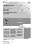
1
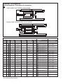
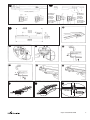
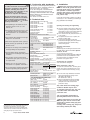
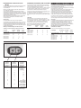
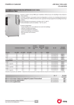
Explosionsgeschützte Leuchten für Zone 2 und Zone 22 Serie: nLLK 08 nLLM 08 Explosion protected light fittings zone 2 and zone 22 Series: nLLK 08 nLLM 08 Luminaires pour atmosphères explosives zone 2 et zone 22 Série: nLLK 08 nLLM 08 3 3465 000 168 D/E/ (-) Betriebsanleitung Operating instructions Mode d’emploi &=7HQWRQiYRGNSRXåLWtVLPåHWHY\åiGDW YHVYpPPDWHĜVNpPMD]\FHXSĜtVOXãQpKR ]DVWRXSHQtVSROHþQRVWL&RRSHU&URXVH +LQGV&($*YHYDãt]HPL +$NH]HOpVL~WPXWDWyWD]DGRWWRUV]iJ Q\HOYpQD&RRSHU&URXVH+LQGV&($*FpJ KHO\LNpSYLVHOHWpQLJpQ\HOKHWLPHJ '.0RQWDJHYHMOHGQLQJHQNDQRYHUV WWHVWLO DQGUH(8VSURJRJUHNYLUHUHVKRV'HUHV &RRSHU&URXVH+LQGV&($*OHYHUDQG¡U ,6HGHVLGHUDWHODWUDGX]LRQHGHOPDQXDOH RSHUDWLYRLQXQDOWUDOLQJXDGHOOD&RPXQLWj (XURSHDSRWHWHULFKLHGHUODDOYRVWUR UDSSUHVHQWDQWH&RRSHU&URXVH+LQGV&($* ((QFDVRQHFHVDULRSRGUiVROLFLWDUGHVX UHSUHVHQWDQWH&RRSHU&URXVH+LQGV&($* HVWDVLQVWUXFFLRQHVGHVHUYLFLRHQRWURLGLRPD GHOD8QLRQ(XURSHD /7âLRVQDXGRMLPRLQVWUXNFLMRVLãYHUVWRVƳ-njVǐ JLPWąMąNDOEąJDOLWHSDUHLNDODXWLDWVDNLQJRMH &RRSHU&URXVH+LQGV&($*DWVWRY\EHMHVDYR ãDO\MH (676HGDNDVXWXVMXKHQGLWRPDULLJLNHHOHV Y}LWHNVLGDRPDULLJLVDVXYDVWDVMDRPDVHVW &RRSHU&URXVH+LQGVL&($*HVLQGXVHVW /9âRHNVSOXDWƗFLMDVLQVWUXNFLMXYDOVWVYDORGƗ YDUDWSLHSUDVƯWMXVXYDOVWVDWELOGƯJDMƗ&RRSHU &URXVH+LQGV&($*SƗUVWƗYQLHFƯEƗ ),17DUYLWWDHVVDWlPlQNl\WW|RKMHHQNllQQ|V RQVDDWDYLVVDWRLVHOOD(8QNLHOHOOl7HLGlQ &RRSHU&URXVH+LQGV&($*HGXVWDMDOWDQQH 0-LVWJƫXMLWROEXGDQLOPDQZDOILOOLQJZD QD]]MRQDOLWDJƫKRPPLQJƫDQGLUUDSSUHĪHQWDQW WD &RRSHU&URXVH+LQGV&($*I SDMMLĪKRP *5ǼĮȞȤȡİȚĮıșİȚİIJĮȡĮıȘIJȦȞȠįȘȖȚȦȞȤȡȘıİ ȦȢıİĮȜȜȘȖȜȦııĮIJȘȢǼǼʌȠȡİȚȞĮȗȘIJȘșİȚĮʌȠ IJȠȞǹȞIJȚʌȡȠıȦʌȠIJȘȢ&RRSHU&URXVH +LQGV&($*³ 1/,QGLHQQRRG]DNHOLMNNDQGHYHUWDOLQJYDQ GH]HJHEUXLNVLQVWUXFWLHLQHHQDQGHUH(8WDDO ZRUGHQRSJHYUDDJGELM8Z&RRSHU&URXVH +LQGV&($*YHUWHJHQZRRUGLJLQJ 36HIRUQHFHVViULDDWUDGXomRGHVWDV LQVWUXo}HVGHRSHUDomRSDUDRXWURLGLRPDGD 8QLmR(XURSHLDSRGHVROLFLWDODMXQWRGRVHX UHSUHVHQWDQWH&RRSHU&URXVH+LQGV&($* 3/1LQLHMV]ąLQVWUXNFMrREVáXJLZRGSRZLHGQLHM ZHUVMLMĊ]\NRZHMPRĪQD]DPyZLüZ SU]HGVWDZLFLHOVWZLHILUP\&RRSHU&URXVH +LQGV&($*QDGDQ\NUDM 6(Q|YHUVlWWQLQJDYGHQQDPRQWDJHRFK VN|WVHOLQVWUXNWLRQWLOODQQDW(8VSUnNNDQYLG EHKRYEHVWlOODVIUnQ(U&RRSHU&URXVH +LQGV&($*UHSUHVHQWDQW 6.7HQWRQiYRGQDREVOXKX9iPYR9DãRP URGQRPMD]\NXSRVN\WQH]DVW~SHQLHVSRORþQRVWL &RRSHU&URXVH+LQGV&($*YR9DãHMNUDMLQH 6/21DYRGLOD]DXSRUDERY9DãHPMH]LNX ODKNR]DKWHYDWHSULSULVWRMQHP]DVWRSQLãWYX SRGMHWMD&RRSHU&URXVH+LQGV&($*Y9DãL GUåDYL Schaltplan / Montagebilder Wiring diagrams / Illustrations for mounting 1 1 Lampe je EVG/ 1 lamp each EVG/ 1 Lampe par EVG 2 Lampen je EVG/ 2 lamps each EVG/ 2 Lampes par EVG) Tabelle 1 Elektrische Daten/ Table 1 electrical data/ Table 1 Caractéristiques Electriques: Ausführung/ DV*1 type/ Modèle mit ohne EVG Typ EVG type EVG type Spannungsbereich Nennstrom in A: Frequenzbereich: Voltage range Rated current in A Frequency range: Plage de tensions courant nominal en A Plage de fréquences: cos ϕ ( 230 V): Kennzeichnung: Marking: Marque zul. Umgebungstemperatur: max. perm.ambient temp.: Temp.ambiante admissible: II 3G Ex nA de II C T4 II 3D Ex tD A22 IP66 T80°C II 3G Ex nA dem II C T4 II 3D Ex tD A22 IP66 T80°C -25°C -> +50°C 0,97 cap. II 3G Ex nA dem II C T4 II 3D Ex tD A22 IP66 T80°C -25°C -> +50°C 50 / 60 Hz 0 Hz 0,97 cap. II 3G Ex nA de II C T4 II 3D Ex tD A22 IP66 T80°C -25°C -> +50°C 0 / 50 / 60 Hz 0,97 cap. II 3G Ex nA dem II C T4 II 3D Ex tD A22 IP66 T80°C -25°C -> +50°C -25°C -> +55°C EVG Luxtronic 220 - 240 V AC 2x36 W 220 - 240 V DC 50 / 60 Hz 0 Hz 0,97 cap. II 3G Ex nA de II C T4 II 3D Ex tD A22 IP66 T80°C -25°C -> +45°C EVG Luxtronic 220 - 240 V AC 2x36 W 220 - 240 V DC 50 / 60 Hz 0 Hz 0,97 cap. II 3G Ex nA de II C T4 II 3D Ex tD A22 IP66 T80°C -25°C -> +50°C 110 - 254 V AC/DC 195 - 250 V AC/DC 0 / 50 / 60 Hz 0,97 cap. II 3G Ex nA dem II C T4 II 3D Ex tD A22 IP66 T80°C -25°C -> +50°C -25°C -> +55°C 220 - 254 V AC 195 - 250 V DC 50 / 60 Hz 0 Hz 0,97 cap. II 3G Ex nA dem II C T4 II 3D Ex tD A22 IP66 T80°C -25°C -> +50°C EVG Luxtronic 220 - 240 V AC 1x58 W 220 - 240 V DC 50 / 60 Hz 0 Hz 0,97 cap. II 3G Ex nA de II C T4 II 3D Ex tD A22 IP66 T80°C -25°C -> +50°C 0 / 50 / 60 Hz 0,97 cap. II 3G Ex nA dem II C T4 II 3D Ex tD A22 IP66 T80°C -25°C -> +50°C -25°C -> +55°C 50 / 60 Hz 0 Hz 0,97 cap. II 3G Ex nA de II C T4 II 3D Ex tD A22 IP66 T80°C -25°C -> +40°C 220 - 254 V AC/DC 195 - 250 V AC/DC 0 / 50 / 60 Hz 0,97 cap. II 3G Ex nA dem II C T4 II 3D Ex tD A22 IP66 T80°C -25°C -> +40°C 220 - 254 V AC/DC 195 - 250 V AC/DC 0 / 50 / 60 Hz 0,97 cap. -25°C -> +45°C 220 - 254 V AC 195 - 250 V DC 50 / 60 Hz 0 Hz 0,97 cap. II 3G Ex nA dem II C T4 II 3D Ex tD A22 IP66 T80°C II 3G Ex nA dem II C T4 II 3D Ex tD A22 IP66 T80°C 220 - 254 V AC 195 - 250 V DC 50 / 60 Hz 0 Hz 0,97 cap. II 3G Ex nA dem II C T4 II 3D Ex tD A22 IP66 T80°C -25°C -> +45°C 50 / 60 Hz 0 Hz 0,97 cap. 110 - 254 V AC/DC 195 - 250 V AC/DC 0 / 50 / 60 Hz 0,97 cap. 220 - 254 V AC 195 - 250 V DC 50 / 60 Hz 0 Hz EVG Luxtronic 220 - 240 V AC 1x36 W 220 - 240 V DC EVG Luxtronic 220 - 240 V AC 2x18 W 220 - 240 V DC 2 x 18 W X X 2 x 18 W X X EVG 05 218 2 x 18 W X X EVG 05 218 + CG-S 1 x 36 W X X 1 x 36 W X X 2 x 36 W X - 2 x 36 W - X 2 x 36 W X X EVG 05 236 2 x 36 W X X EVG 05 236 + CG-S 1 x 58 W - X 1 x 58 W X X 2 x 58 W X X 2 x 58 W X - EVG 05 258 2 x 58 W - X EVG 05 258 EVG 05 136 EVG 05 158 110 - 254 V AC/DC 195 - 250 V AC/DC 110 - 254 V AC/DC 195 - 250 V AC/DC EVG Luxtronic 220 - 240 V AC 2x58 W 220 - 240 V DC 2 x 58 W X - EVG 05 258 + CG-S 2 x 58 W - X EVG 05 258 + CG-S *1 DV = zweiseitige Durchgangsverdrahtung -25°C -> +50°C -25°C -> +55°C -25°C -> +40°C 1060 (18 W), 1660 (36 W) 188 44 4a 2a 76 130 2 2 736 (18 W), 1336 (36 W) 33 33 150 20 150 34 2b 4 Anschlußraum für ein Kabel Anschlußraum für zwei Kabel Connection compartment for 1 cable Connection compartment for 2 cables Compartiment de raccordement pour 1 câble Compartiment de raccordement pour 2 câbles 732 (18 W) 1332 (36 W) 1632 (58 W) 400 (18 W) 700 (36 W) 700 (58 W) M8, nLLK 2 08 15 tief/deep/ profond 4 65 130 Sechskant/Hexagon... SW 13 188 46 760 (18 W) 1360 (36 W) 1660 (58 W) 10 11 12 ≥ 2 mm Cooper Crouse-Hinds GmbH 3 1. Sicherheitshinweise Zielgruppe: Elektrofachkräfte und unterwiesene Personen. Beachten Sie die nationalen Unfallverhütungs- und Sicherheitsvorschriften und die nachfolgenden Sicherheitshinweise, die in dieser Betriebsanleitung mit einem ( ) gekennzeichnet sind! U Diese Leuchte darf nicht in explosionsgefährdeten Bereichen der Zonen 0,1 und 20, 21 eingesetzt werden! U Die Anforderungen der EN 61241-0 und -1 in Bezug auf übermäßige Staubablagerungen und Temperatur, sind vom Anwender zu beachten. U Die auf der Leuchte angegebenen technischen Daten sind zu beachten! U Betriebsmittel vor Öffnen spannungsfrei schalten! U Mehrfaches, kurzzeitiges Einschalten vermeiden! U Umbauten oder Veränderungen an der Leuchte sind nicht zulässig! U Die Leuchte ist bestimmungsgemäß in unbeschädigtem und einwandfreiem Zustand zu betreiben! U Als Ersatz dürfen nur Originalteile von Cooper Crouse-Hinds (CCH)/CEAG verwendet werden! U Reparaturen dürfen nur von CCH/CEAG oder einer qualifizierten „Elektrofachkraft“ durchgeführt werden! U Betriebsanleitung während des Betriebes nicht in der Leuchte belassen! 2. Normenkonformität 4. Installation Diese explosionsgeschützte Leuchte entspricht den in der Konformitätserklärung aufgeführten Normen und ist gemäss DIN EN ISO 9001:2000 entwickelt, gefertigt und geprüft. Diese Leuchte ist zum Einsatz in explosionsgefährdeten Bereichen der Zonen 2/22 gemäß EN 60079-10 und EN 61241-10 geeignet. Die für das Errichten und Betreiben von elektrischen Betriebsmitteln geltenden Sicherheitsvorschriften und des Gerätesicherheitsgesetzes sowie die allgemein anerkannten Regeln der Technik sind einzuhalten! Transport und Lagerung der Leuchte ist nur in Originalverpackung und in angegebener Lage gestattet! 3. Technische Daten: Leuchten mit Zweistiftlampenfassung G13: nLLK 08 018/18: 2 x 18 W nLLK 08 018/18 (CG-S): 2 x 18 W nLLK 08 036: 1 x 36 W nLLK 08 036/36 (CG-S): 2 x 36 W nLLK 08 058: 1 x 58 W nLLK 08 058/58 (CG-S): 2 x 58 W nLLM 08 018/18: 2 x 18 W nLLM 08 036/36: 2 x 36 W Kennzeichnung nach 94/9/EG und Norm: siehe Tabelle 1 Konformitätserkärung: PTB 08 ATEX 2008 Bemessungsspannung siehe Tabelle 1 Bemessungsfrequenz: 50 - 60 Hz Lampenbestückung: Leuchtstofflampen mit Zweistiftsockel G13 nach: 18 W IEC 60081-22/20 36 W IEC 60081-24/20 58 W IEC 60081-21/22 Schutzart nach EN 60529 (IEC 60 529): IP 66 Schutzklasse nach EN 61140: I zul. Umgebungs1) temperatur : siehe Tabelle 1 Lagertemperatur in Originalverpackung: -40 ºC ... +60 ºC Klemmvermögen Steck-Anschlussklemme: 2 x 2,5 mm² Klemmvermögen Schraub-Anschlussklemme 2x je Klemme: einadrig mehradrig min.: 1,5 mm2 2,5 mm2 max.: 6,0 mm2 4,0 mm2 Leiterquerschnitt bei Durchgangserdrahtung: 2,5 mm2 für max. 16A Leitungseinführung Kunststoff: M25 x 1,5 für Leitungen Ø 8 bis 17 mm Metallgewinde: M20 x 1,5 Nur für festverlegte Leitungen Prüfdrehmoment für Kabel- und Leitungseinführung M25 x 1,5: 5,0 Nm Prüfdrehmoment für Entlüftungsstutzen M25 x 1,5: 10,0 Nm Prüfdrehmoment für Druckschraube: für min. Kabel Ø 5,00 Nm für max. Kabel Ø 3,50 Nm Leuchten- und Montageabmessungen: siehe Bild 2 Leuchtengewichte nLLK 08 018/18: ca. 3,6 kg nLLK 08 036: ca. 5,6 kg nLLK 08 036/36: ca. 5,8 kg nLLK 08 058: ca. 6,7 kg nLLK 08 058/58: ca. 6,9 kg nLLM 08 018/18: ca. 6,1 kg nLLM 08 036/36. ca. 8,4 kg nLLK 08018/18 CG-S ca. 5,6 kg nLLK 08 036/36 CG-S ca. 8,0 kg nLLK 08 058/58 CG-S ca. 9,0 kg 1) Intensive Sonneneinstrahlung in Regionen mit hohen Umgebungstemperaturen kann im Leuchteninneren zu unzulässig hohen Erwärmungen führen. Eine Reduzierung der Lebensdauer des EVGs kann eine Folge hiervon sein. Zur Vermeidung sollten in diesen Regionen tagsüber die Leuchten über einen Lichtsensor geschaltet werden. 4 Cooper Crouse-Hinds GmbH Bei besonderen Umwelteinflüssen wird empfohlen den Entlüftungsstutzen (GHG960 1954 R0002) zu verwenden. Die Leuchte mit der Vorzugsleuchtrichtung nach unten montieren! Öffnen und Schließen der Leuchte: U Den Zentralverschluss mit Steckschlüssel (Schlüsselweite SW 13) um ca. 90º bis zur Raststellung drehen und Schutzwanne abklappen, siehe Bild 3. U Schutzwanne ein- und ausbauen, siehe Bild 6 und 7. U Die Schutzwanne ist wahlweise beidseitig scharnierbar. U Schutzwanne zum Verschließen der Leuchte fest an das Leuchtengehäuse andrücken und den Zentralverschluss um 90º drehen. Montageabmessungen: siehe Bild 2 Beachten Sie beim Befestigen des Montagezubehörs an der Leuchte die max. Gewindetiefe der Montagebohrung von 12 mm! Verwenden Sie keine zu langen Schrauben! Montagezubehör: siehe CCH/CEAG Katalog. Netzanschluss nLLK 08... : Zum Öffnen des Anschlussraumes grünen Drehgriff in Pfeilrichtung bis zum Anschlag drehen, dann ziehen und die Klappe abklappen, siehe Bild 4 und 5. U Die Luft und Kriechstrecken im Inneren der Leuchte sind für den Verschmutzungsgrad 2 ausgelegt. (EN 60644, EN 60598-1, EN 60079-0 / 6.1 Anmerkung 3) U Beim Anschließen der Leuchte mit flexibler Leitung ist auf entsprechende Zugentlastung zu achten (Trompetenverschraubungen mit mind. Schutzart IP66). Es dürfen nur nach 94/9/EG bescheinigte KLE´s und Verschlussstopfen verwendet werden. Um die Zündschutzart „nA“ zu gewährleisten nur KLE´s mit der Mindestschutzart IP66 verwenden. Die entprechende Betriebsanleitung des Herstellers ist zu beachten. Bei nicht benutzten Kabel-und Leitungseinführungen ist die Schutzscheibe zu entfernen und durch einen bescheinigten Verschlussstopfen (Prüfdrehmoment 3,5 Nm) zu verschließen. Beim Verschließen mit einem Verschlussstopfen stets beide Dichtungseinsätze verwenden! (mindestens Schutzart IP66). Nicht benutzte Gewindebohrungen für KLEs sind mit einem bescheinigten Schraubverschluss zu verschließen (mindestens Schutzart IP66). U Die Leitungen sind durch die Kabel- und Leitungseinführung einzuführen, siehe Bild 5. U Für Leitungen von 8 bis 12 mm sind beide Dichtungseinsätze - von 12 bis 17 mm ist nur der äußere Dichtungseinsatz zu verwenden. Der korrekten Sitz des verbleibenden Dichtungseinsatzes in der Verschraubung muss sichergestellt sein. U Die abisolierten Leitungen gem. Klemmenbezeichnung (siehe Schaltplan, Seite 2) sind in die Steckklemmen einzuführen. Abisolierlänge 2,5 mm²: 8 - 9 mm U Bei Verwendung von mehr- oder feindrähtigen Anschlussleitungen sind die Aderenden entsprechend den geltenden nationalen und internationalen Vorschriften zu behandeln (z.B. Verwenden von Aderendhülsen). Sind Schraubklemmen vorhanden, müssen auch nicht benutzte Klemmen angezogen werden! Bei Einfachbelegung der Klemmen kein Umbiegen (Schlaufe) der Adern notwendig! Installation nLLM 08... Die Montage und Installation der Mastleuchte erfolgt in folgender Reihenfolge: U Lösen Sie die drei Kreuzschlitzschrauben im Deckel des Mastanschlußraumes, siehe Bild 2a, Pos. 1. U Anschlußraum öffnen, indem Sie den Deckel abklappen, siehe Bild 2a, Pos. 2. U Verriegelungsbügel des Kabel- und Leitungseinführungsstutzens bis zum Anschlag hochziehen und Abdeckplatte abnehmen, siehe Bild 2a, Pos. 3. U Kabel- und Leitungseinführungstutzen aus den Führungsnuten im Anschlußraum entnehmen. U Mastrohr oder das Rohr des Wandarmes von jeweils (Ø 42 mm (Bild 2a, Pos. 4) bis zum Anschlag in die Öffnung der Mastleuchte einführen, siehe Bild 2a, Pos. 4a. U Leuchte ausrichten und die vormontierten Spezialschrauben M6 anziehen, Drehmoment 3,0 Nm, siehe Bild 2a, Pos. 5. U Die Leitung durch das Rohr einführen und auf die entsprechende Länge abisolieren. U Die Leitung durch die Ex-Kabel- und Leitungseinführung (KLE) einführen und mit der Druckschraube der KLE die Leitung anziehen (Drehmoment 3,5 Nm). U Den kompletten Träger (mit eingeführter Leitung) in die Führungsnuten der Mastleuchte einsetzen, siehe Bild 2a, Pos. 6. U Den Träger mit dem Verriegelungsbügel verschließen, siehe Bild 2a, Pos. 3. U Die Leitung in die Zugentlastung legen und anziehen, siehe Bild 2a, Pos. 7. U Dann die Leitung entsprechend der Klemmenbezeichnung anschließen. Achtung: Bei nicht benutzten Kabel-und Leitungseinführungen ist die Schutzscheibe zu entfernen und durch einen Verschlussstopfen (Prüfdrehmoment 3,5 Nm) zu verschließen. Beim Verschließen mit einem Verschlussstopfen stets beide Dichtungseinsätze verwenden! (mindestens Schutzart IP66). Einsetzen der Lampen: Es dürfen nur solche Lampen, die für diese Leuchten zugelassen sind verwendet werden (siehe technische Daten und Typenschild)! Die Zweistiftsockellampe (G13) in beide Fassungen bis zum Anschlag einstecken, so dass an jeder Seite der Lampe beide Stifte im Eingriff der Fassung sind. Danach die Lampe in Raststellung drehen, siehe Bild 8 und Bild 9. Achtung! Lampenwechsel nur im ausgeschalteten Zustand. Option: automatische Abschaltung über 2-poligen Leuchtenschalter beim Öffnen der Schutzwanne. Haushaltsspülmittel in vorgeschriebener Verdünnung mit Wasser! Die Wassertemperatur darf maximal 50°C betragen. Spülen Sie anschließend mit klarem Wasser nach, da sonst Spannungsrisse in der Schutzwanne entstehen können! U Beachten Sie für den Lampenwechsel die Wechselintervalle gemäß Vorgabe der Lampenhersteller! Instandsetzung Vor dem Austausch oder der Demontage von Einzelteilen ist folgendes zu beachten: Schalten Sie das Betriebsmittel vor dem Öffnen oder vor Instandhaltungsarbeiten erst spannunsfrei! Trennen sie auch den Batteriestromkeis vom Gerät! Verwenden Sie nur CCH/CEAG Originalersatzteile (siehe CCH/CEAG Ersatzteilliste)! Programmänderungen und Ergänzungen sind vorbehalten. Bei der Entsorgung nationale Abfallbeseitigungsvorschriften beachten! Die Kunststoffmaterialien sind mit Materialbezeichnungen versehen. 5. Inbetriebnahme U Vor der Inbetriebnahme ist die korrekte Funktion und Installation der Leuchte in Übereinstimmung mit dieser Betriebsanleitung und anderen zutreffenden Bestimmungen zu überprüfen! U Isolationsmessungen dürfen nur zwischen PE und Außenleiter • L1 (L2, L3) sowie zwischen PE und N durchgeführt werden! - Meßspannung: max. 1kVAC/DC - Meßstrom: max. 10 mA U Die Leuchte nur im geschlossen betrieben. 6. Instandhaltung Die für die Instandhaltung, Wartung und Prüfung die geltenden Bestimmungen sind einzuhalten (zum Beispiel EC 60079-17). Wartung Im Rahmen der Wartung sind vor allem die Teile, von denen die Schutzart abhängt, zu prüfen z.B.: U Gehäuse und Schutzwannen auf Risse und Beschädigungen. U Dichtungen auf Beschädigungen. U Klemmen, Verschraubungen und Verschlussstopfen auf festen Sitz. U Wegen der Gefahr elektrostatischer Aufladung darf die Leuchte nur mit einem feuchten Tuch oder Schwamm gereinigt werden! Benutzen Sie dazu nur übliche Cooper Crouse-Hinds GmbH 5 1. Safety instructions: For skilled electricians and trained personnel in accordance with national legislation, including the relevant standards and, where applicable, in acc. with IEC 60079-17 on electrical apparatus for explosive atmospheres. Observe the national safety rules and regulations for prevention of accidents and the following safety instructions which are marked with an ( ) in these operating instructions! U The light fitting is not suitable for use in hazardous areas of zone 0, 1 and zone 20, 21! U The requirements of the EN 61241-0 and 1 regarding excessive dust deposits and temperature to be considered from the user. U The technical data indicated on the light fitting are to be observed! U Disconnect equipment before opening! U Avoid powering up repeatedly for short periods of time. U Changes of the design and modifications to the light fitting are not permitted! U The light fitting shall be operated as intended and in undamaged and perfect condition! U Only genuine Cooper Crouse-Hinds (CCH)/CEAG spare parts may be used for replacement! U Repairs may only be carried out by CCH/CEAG or a qualified “electrician”! U Do not keep these operating instructions inside the light fitting during operation! Intensive sun radiation in areas of high ambient temperatures may cause inadmissible temperature rise inside of the luminaire. This may result a decrease in lifetime of the electronic ballast (EVG). Therefore those luminaires should be switched off during daytime by a photocell control. 1) 6 Cooper Crouse-Hinds GmbH 2. Conformity with standards: 4. Installation This explosion protected light fitting meets the requirements of the standards specified in the EC Declaration of conformity. It has been designed, manufactured and tested according to the state of the art and according to DIN EN ISO 9001: 2000. The light fitting is suitable for use in hazardous areas of zone 2/22 according IEC 60079-10 and IEC 61241-10. Observe the respective national regulations as well as the general rules of engineering which apply to the installation and operation of electrical apparatus! Transport and storage of the luminaire is permitted in original packing and specified position only! 3. Technical data Light fittings with G13 bi-pin cap nLLK 08 018/18: 2 x 18 W nLLK 08 018/18 (CG-S): 2 x 18 W nLLK 08 036: 1 x 36 W nLLK 08 036/36 (CG-S): 2 x 36 W nLLK 08 058: 1 x 58 W nLLK 08 058/58 (CG-S): 2 x 58 W nLLM 08 018/18: 2 x 18 W nLLM 08 036/36: 2 x 36 W Marking accd. 94/9/EC and directive: see table 1 Statement of Confirmation: PTB 08 ATEX 2008 rated voltage: see table 1 rated frequenzy: 50 - 60 Hz Lamps to be fitted: Fluorescent lamps with G13 bi-pin cap to: 18 W IEC 60081-22/20 36 W IEC 60081-24/20 58 W IEC 60081-21/22 Protection acc. to EN/IEC 60529: IP 66 Insulation class to EN 61140: I max. permissible ambient temperature: see table 1 Storage temperature in original packing: -40 °C to + 60 ºC Supply terminal clamping capacity per clampterminal (2.5 mm²): 2 x 2.5 mm2 Supply terminal clamping capacity 2x per screw-terminal: single-wire multi-wire min. 1.5 mm2 2.5 mm2 max. 6.0 mm2 4.0 mm2 Conductor cross-section with through-wiring: 2.5 mm2 for max. 16 A Cable entries moulded plastics: M25x1.5 for cable Ø 8 to 17 mm Metal thread: M 20 x 1.5 For permanently laid cables only. Test-torque for M25 x 1,5 cable entry: 5.0 Nm Test-torque for pressure screw: min. cable Ø: 5.0 Nm max. cable Ø: 3.5 Nm Dimensions of light fittings and for mounting: see fig. 2 nLLK 08 018/18: ca. 3,6 kg nLLK 08 036: ca. 5,6 kg nLLK 08 036/36: ca. 5,8 kg nLLK 08 058: ca. 6,7 kg nLLK 08 058/58: ca. 6,9 kg nLLM 08 018/18: ca. 6,1 kg nLLM 08 036/36. ca. 8,4 kg nLLK 08018/18 CG-S ca. 5,6 kg nLLK 08 036/36 CG-S ca. 8,0 kg nLLK 08 058/58 CG-S ca. 9,0 kg In special environment condition it could be necessary to use a breathing and drainage plug (GHG960 1954 R0002)! Opening and closing the light fitting U Turn the central locking device with a box spanner (opening of the spanner SW 13) through 90° to its lock-in position and fold down the protective bowl, see fig. 3 U Fit in and remove the protective bowl acc. to fig. 6 and 7. U The protective bowl can, at option, be hinged on either side. U To close the light fitting, press the protective bowl tightly onto the luminaire housing and turn the central locking device through 90°. Mounting dimensions see fig. 2 When fixing the mounting accessories onto the light fitting, observe the max. depth of thread of 12 mm! Do not use too long screws! Installing the light output upwards additional protection has to be assembled to avoid permanent water accumulations at the protective bowl gasket area. Accessories for mounting See CCH/CEAG catalogue. Mains connection nLLK 08... To open the connection box, turn the green handle to its stop in the direction of arrow, then pull it and fold down the flap, see fig. 4+5. U The air and creep distances inside the light are designed for soiling level 2. (EN 60644, EN 60598-1, EN 60079-0/6.1 Note 3) U When connecting the light to a flexible cable, ensure the correct strain relief (trumpet screw with at least IP66 protection class). Only cable entries and sealing plugs certified to 94/9/EC may be used. To guarantee protection type "nA", use only cable entries with at least IP66 protection class. The corresponding manufacturer's Operating Manual must be observed. Where cable entries are not used, the protective glass must be removed and sealed with a certified sealing plug (test torque 3.5 Nm). If sealing with a sealing plug, always use both sealing inserts! (min. IP66). U Introduce the cable through the cable entry, see fig. 5. U Use both sealing inserts for cables from 8 to 12 mm, and the outer sealing insert only for cables from 12 to 17 mm. Pay attention to the proper fit of the sealing insert remaining in the cable gland. U Plug the bared conductors to the terminals in accordance with the terminal marking (see wiring diagram, page 2). stripping length 2.5 mm²: 8 - 9 mm. U If multi- or fine-wire connecting cables are used, the wire ends will have to be handled in acc. with the applicable national and international rules (e. g. use of ferrules). When screw-terminals are used also tighten vacant terminals! With single connection of the terminal no bending (loop) of the conductor required! Installation of the nLLM 08 ... The pole mounted light fitting is mounted and installed in the following order: U Unscrew the three recessed head screws in the cover of the pole connecting compartment, see fig. 2a, item 1. U Open the connecting compartment by folding down the cover, see fig. 2a, item 2. U Pull the stay shackle of the cable entry socket up to its stop and take off the cover plate, see fig. 2a, item 3. U Remove the cable entry sockets from the guiding grooves in in the connecting compartment. U Then the pole mounting tube or the tube of the wall socket of 42 mm Ø each (fig. 2a, item 4) is pushed home into the opening of the light fitting, see fig. 2a, item 4a. U Adjust the light fitting and screw down the preassembled M 6 special screws, applying a torque of 3.0 Nm, see fig. 2a, item 5. U Introduce the cable through the tube and strip the insulation to the required length. U Introduce the cable through the Ex cable entry (KLE) and tighten it down with the pressure screw of the cable entry (3.5 Nm torque). U The complete support (with the cable being introduced) is put into the guiding grooves of the pole mounted light fitting, see fig. 2a, item 6. U Lock the support with the stay shackle, see fig. 2a, item 3. U Insert the cable into the pull-relief and tighten it down, see fig. 2a, item 7. U Then connect the cable in accordance with the terminal marking. Attention In case of unused cable entries, remove their protective cover and close the entries with a blanking plug (test-torque of 3.5 Nm). When closing the gland with a blanking plug, always use both sealing inserts! Fitting the lamps Only use such lamps that have been certified for these light fittings, see Technical data and type label! The bi-pin lamp (G13) is to be inserted to its stop into both holders so that both pins on either side of the lamp engage in the holder. Then turn the lamp to its lock-in position, see fig. 8. Attention! Lamp exchange must be carried out while energy is switched off. Option: automatic double-pole switch while opening the protective bowl (IP 66). 5. Taking into operation U Because of the risk of an electrostatic charge, the light fitting shall only be cleaned with a damp cloth or sponge! Only use customary household washingup liquid diluted in water as specified! The water temperature may be max. 50ºC. After that, rinse with clear water to prevent the risk of tension cracks in the protective bowl! U Lamp replacement: Keep replacement intervals as specified by the lamp manufacturer! Repair Prior to replacing or removing any components, observe the following: Cut the apparatus off the voltage before opening it or carrying out repairs! Cut off as well the battery circuit! Only use certified genuine CCH/CEAG spare parts! (See CCH/CEAG spare parts list). Subject to alteration or supplement of this product series. Regarding waste disposal, observe the relevant national regulations! All components are marked with relevant material signs. U Prior to operation, check the light fitting for its proper functioning and installation in compliance with these operating instructions and other applicable regulations! U Only carry out insulation measurements between PE and the external conductor L1(L,L2,L3) as well as between PE and N! - measuring voltage: max. 1 kV AC/DC - measuring current: max. 10 mA U Die Leuchte nur im geschlossen betrieben. 6. Maintenance Observe the national regulations applicable to the maintenance, servicing and test of electrical apparatus as well as the general rules of engineering (e.g. IEC 60079-17)! Servicing When servicing, in particular those components that affect the type of protection, will have to be checked, e. g.: U Housing and protective bowl for any cracks or damages. U Gaskets for their perfect condition. U Terminals and blanking plugs for their firm fit. • Cooper Crouse-Hinds GmbH 7 1. Consignes de sécurité Pour le personnel électricien qualifié et le personnel instruit suivant la règlementation légale, y compris les normes respectives ainsi que, le cas échéant, CEI 60079-17 pour apppareils électriques utilisables en atmosphère explosive. Veuillez respecter les prescriptions nationales de sécurité et de prévoyance contre les accidents ainsi que les consignes de sécurité qui sont ) dans ce mode marquées d’un ( d’emploi! Ce luminaire ne convient pas a l’emploi en atmosphère explosive de zones 0, 1, et 20, 21! Les exigences des EN 61241-0 et -1 en ce qui concerne des dépôts de poussière démesurés et une température doivent être considérées par I’utilisateur. Les caractéristiques techniques indiquées sur le luminaire doivent être respectées! Avant d’ouvrir l’enveloppe, débrancher le dispositif de la tension ou prendre des mesures préventives appropriées. Eviter les mises sous tension de courte durée et répétées! Il n’est pas permis de transformer ou de modifier le luminaire! Le luminaire ne doit être exploité que pour la fonction qui lui est dévolue et qu’en état intact et parfait! Seules des pièces de rechange d’origine Cooper Crouse-Hinds (CCH)/ CEAG doivent être employées pour le remplacement! Des réparations ne doivent être exécutées que par Cooper CrouseHinds (CCH)/CEAG ou par un «électricien» qualifié! Ce mode d’emploi ne doit pas être laissé dans le luminaire pendant son exploitation! Le rayonnement solaire intensive dans des régions à température ambiante élevée peut provoquer à l’intérieur du luminaire un échauffement extensif. Ceci peut impliquer une réduction de durée de vie considérable. Pour pallier à cela, il est préconiser d’utiliser un interrupteur photoélectrique. 1) 8 Cooper Crouse-Hinds GmbH 2. Conformité avec les normes: 4. Installation Ce luminaire pour atmosphère explosive correspond aux exigences de la norme reprises dans la déclaration de conformité et aux règles (instructions) de CE „appareils et systemes protégés pour l’emploi déterminé en atmosphère explosive“ (94/8/CE) et compatibilité electromagnetique (2004/108/CEE) Il a été conçu, construit et testé selon l’état actuel de la technique et selon DIN EN ISO 9001:2000. Ce luminaire convient a l’utilisation en atmosphère explosive de zone 2, 22 selon EN 60079-10 et EN 61241-10. Lors de l’installation et de l’exploitation des appareils électriques, les règlements nationaux ainsi que les règles de la technique généralement reconnues doivent être respectés! Le transport et le stockage ne sont permis que dans l’emballage original et dans la position spécifiée! 3. Caractéristiques techniques: Luminaires avec douille de lampe double broche G13: nLLK 08 018/18): 2 x 18 W nLLK 08 018/18 (CGS): 2 x 18 W nLLK 08 036: 1 x 36 W nLLK 08 036/36 (CGS): 2 x 36 W nLLK 08 058: 1 x 58 W nLLK 08 058/58 (CGS): 2 x 58 W nLLM 08 018/18 2 x 18 W nLLM 08 036/36: 2 X 36 W Marquage selon directive 94/9/CE: Voir tableau 1 Certificat d’essai CE du modèle type: PTB 08 ATEX 2008 Lampes â utiliser: Lampes fluorescentes â culot double broche: G13 selon 18 W CEI 60081-22/20 36 W CEI 60081-24/20 58 W CEI 60081-21/22 Indice de protection selon EN/CEI 60529: IP 66 Classe d’isolation selon EN 61140: I Température ambiante admissible 1): Voir tableau 1 Température de stockage dans l’emballage original: -40 ºC â +60 ºC Capacité de serrage des bornes sans vis, 2 x par bornes 2,5 mm²: 2x 2,5 mm2 2 x par bornes à visser: unifilaire multifilaire min. 1,5 mm2 2,5 mm2 max. 6,0 mm2 4,0 mm2 Section transversale du conducteur en cas d’interconnexion: 2,5 mm2 pour 16 A au maxi Entrée de câble en plastique: modèle standard M25x1,5 pour câbles d’un Ø de 8 â 17 mm Entrées de câble en métal: M20 x 1,5 Uniquement pour les câblages fixes Couple pour l’entrée de câble M25 x 1,5: 5,0 Nm Couple pour la vis de pression: min câble Ø: 5,0 Nm max câble Ø: 3,5 Nm Dimensions des luminaires et de fixation: voir fig. 2 Poids des luminaires nLLK 08 018/18: env. 3,6 kg nLLK 08 036: env. 5,6 kg nLLK 08 036/36: env. 5,8 kg nLLK 08 058: env. 6,7 kg nLLK 08 058/58: env. 6,9 kg nLLM 08 018/18: env. 6,1 kg nLLM 08 036/36. env. 8,4 kg nLLK 08018/18 CG-S env. 5,6 kg nLLK 08 036/36 CG-S env. 8,0 kg nLLK 08 058/58 CG-S env. 9,0 kg Ouverture et fermeture du luminaire: Tourner le verrou central avec la clé â douille (ouverture de clé SW 13) de 90º dans sa position de crantage et rabattre la vasque de protection, voir fig. 3 et 4. Monter et démonter la vasque de protection suivant fig. 6 et 7. La vasque de protection est pourvue d’une charnière des deux côtés ce qui permet de la suspendre de chaque côté. Pour fermer le luminaire, presser la vasque de protection contre le boîtier du luminaire et tourner le verrou central de 90º. Dimensions de fixation voir fig. 2. Respecter lors de la fixation des accessoires de montage au luminaire que les trous de fixation doivent avoir une profondeur du pas de 12 mm au maxi! Ne pas utiliser de vis trop longues! Accessoires pour le montage voir le catalogue CCH/CEAG. Branchement sur secteur nLLK 08 ...: Afin d’ouvrir la boîte de connexion, tourner la poignée rouge jusqu’à sa butée, puis la tirer et rabattre la trappe, voir Introduire le câble par l’entrée de câble, voir fig. 4 et 5. Généralement, seuls des bouchons de fermeture et des entrées de câble certifiés peuvent être utilisés. Seuls les bornes et bouchons homologués ATEX 94/9/CE peuvent être utilisés. Pour garantir le mode de protection contre l'inflammation « nA », utiliser uniquement des bornes avec au minimum l'indice de protection IP66. Respecter le mode d'emploi du fabricant. En cas d’entrées de câble non utilisées, leur disque protecteur doit être enlevé, et l’entrée doit être fermée avec un bouchon de fermeture (couple de 3,5 Nm). Lorsqu’ un bouchon de fermeture est mis, toujours utiliser les deux joints d’étanchéité! Introduire le câble par l’entrée de câble, voir fig. 5. Utiliser les deux joints d’étanchéité pour les câbles de 8 à 12 mm, et le joint extérieur seul pour les câbles de 12 à 17 mm. Veiller au propre logement du joint d’étanchéité demeuré dans la presseétoupe. Connecter les câbles aux bornes PE,N,L1,(L2,L3) suivant le repérage des bornes (voir schéma des connexions sur page 2). Dénudage des conducteurs: 2,5 mm² => 8 - 9 mm En cas d'occupation simple de la borne, il n'est pas nécessaire de replier le conducteur (boucle!) Serrer aussi les bornes non utilisées! Installation nLLM 08 .. Le montage et l’installation du luminaire pour fixation sur mât se fait dans l’ordre suivant: Dévisser les trois vis à fentes en croix dans le couvercle du compartiment de raccordement du poteau, voir fig. 2, pos. 1. Ouvrir le compartiment de raccordement en rabattant le couvercle, voir fig. 2a, pos. 2. Lever l’étrier de verrouillage de la tubulure d’entrée de câble jusqu’à sa butée et enlever la plaque de recouvrement, voir fig. 2a, pos. 3. Sortir la tubulure d’entrée de câble des rainures de guidage dans le compartiment de raccordement. Introduire le tube du poteau ou de la console d’un diamètre de 42 mm chacun (fig. 2a, pos. 4) jusqu’ à la butée dans l’orifice du luminaire,voir fig. 2, pos. 4a. Ajuster le luminaire et serrer à fond les vis spéciales M6 montées au préalable avec un couple de 3,0 Nm, voir fig. 2a, pos. 5. Puis introduire le câble par le tube et le dénuder de la longueur requise. Introduire le câble par l’entrée de câble Ex (KLE) et le serrer à fond au moyen de la vis de pression de l’entrée de câble (couple de 3,5 Nm). Puis le support complet (avec le câble mis en place) est posé dans les rainures de guidage du luminaire pour fixation sur mât, voir fig. 2a, pos. 6. Verrouiller le support au moyen de l’étrier de verrouillage, voir fig. 2a, pos. 3. Poser le câble dans la décharge de traction et le serrer à fond, voir fig. 2a, pos. 7. Attention: En cas d’entrées de câble non utilisées, leur disque protecteur doit être enlevé, et l’entrée doit être fermée avec un bouchon de fermeture (couple de 3,5 Nm). Lorsqu’ un bouchon de fermeture est mis, toujours utiliser les deux joints d’étanchéité! (IP 66) Mise en place de la lampe N’utiliser que des lampes homologuées pour ces luminaires, voir Caractéristiques techniques et plaque signalétique! Introduire la lampe double broche (G13) jusqu’à sa butée dans les deux douilles de manière que les deux broches de chaque côté de la lampe soient prises par la douille. Puis tourner la lampe en position de crantage selon fig. 9. Attention! Remplacement de la lampe uniquement hors tension! 5. Mise en service Avant la mise en service des luminaires, il faut vérifier s’ils sont branchés et fonctionnent en conformité avec ce mode d’emploi et avec d’autres règlements applicables! Des mesures d’isolation ne doivent être effectuées qu’entre PE et le conducteur extérieur L1(L2,L3) ainsi qu’entre PE et N! - tension de mesure: 1 kV CA/CC au maxi - courant de mesure: 10 mA au maxi 6. Entretien: Les bouchons d’obturation et les bornes sont-ils bien serrés? Vu le risque d’une charge électrostatique, le luminaire ne doit être nettoyé qu’avec un chiffon humide et non fibreux ou qu’avec une éponge! Utiliser uniquement un détergent ménager dilué avec de l’eau comme prescrit! La température de l’eau ne doit pas dépasser 50 °C au maxi. Rincer ensuite à l’eau claire afin d’éviter que n’apparaissent des fissures dues à la contrainte exercée sur la vasque de protection Remplacement de la lampe: Respecer les intervalles de remplacement selon L'indication du fabricant de lampes! Réparation Avant de remplacer ou d’enlever des composants, il faut observer le mode suivant: Mettre l’appareil hors tension avant de l’ouvrir ou de le réparer! N’utiliser que des pièces de rechange approuvées d’origine CCH/CEAG! (Voir liste des pièces de rechange CCH/CEAG) Sous réserve de modification ou de supplément de cette série de produits. Quant à l’enlèvement des déchets, veuillez respecter la règlementation nationale en vigueur! Quant à l’enlèvement des déchets, veuillez respecter les règlements nationaux respectifs! En ce qui concerne l’entretien, le test et la ré•paration des appareils électriques pour atmosphère explosive, les règlements nationaux y applicables par exemple CEI 60079-17 ainsi que les règles de la technique généralement reconnues devront être respectés! Entretien Lors de l’entretien surtout les composants dont dépend le mode de protection, doivent être vérifié, par ex.: Le boîtier et la vasque de protection présentent-ils des fissures ou des signes d’avarie? Les joints d’échantéité sont-ils efficaces? Puis raccorder à vis le câble suivant le repérage des bornes. Cooper Crouse-Hinds GmbH 9 Installation der Leuchte mit CG-SModul Das CG-S Modul überwacht und meldet an das angeschlossene CEAG Notlichtversorgungssystem die Funktion der Leuchtstofflampe. Mit dem CG-S-Überwachungsmodul mit Codierschalter für max. 20 Adressen kann die CG-S Leuchte als einzelüberwachte Notleuchte an CEAG Notlichtversorgungssystemen betrieben werden. Hierbei kann der Betreiber die Schaltungsart frei programmieren. So können an einem Endstromkreis bis zu 20 Leuchten in unterschiedlichen Schaltungsarten betrieben werden. Weitere Informationen zu den Schaltungsarten entnehmen sie den technischen Unterlagen der verwendeten Notlichtversorgungsgeräte. Adressierung Vor Inbetriebnahme der Leuchte muß die individuelle Leuchtenadressierung eingestellt werden. Hierzu ist mit einem geeigneten Schraubendreher die gewünschte Adresse (1 - 20) am Adressschalter, einzustellen (Pfeil auf Zahl, Bild A). Soll die Leuchte nicht überwacht werden, ist immer die Stellung 0/0 einzustellen (Siehe Tabelle B) Zulässige Anschlussleistung nicht überschreiten! Zulässige Leuchtenanzahl je Abgangsstromkreis: 2-lampig nLLK/M nLLK/M nLLK 18/18 36/36 58/58 Anschluss an CEAG SKU 2x3 A CG-S SKU 1x6 A CG-S SKU 4x1 A CG SKU 2x3 A CG SKU 1x6 A CG 16 20 5 12 18 9 17 3 9 17 6 11 2 6 11 (A) Adresssierung/Addressing/Adressage Adressschalter 1/ Adressschalter 2/ Leuchtenadresse/ Address Address Luminaire switch 1/ switch 2/ address/ Position de Position de Adresse de l’interrupteur 1 l’interrupteur 2 luminaire 0 0 Überwachung aus/ Monitoring off/ aucune surveillance 0 1 1 0 2 2 ... ... ... 1 0 10 1 1 11 ... ... ... ... ... ... 2 2 0 1 ... 9 ... 9 20 nicht zulässig not permissable/ pas possible ... nicht zulässig/ not permissable/ pas possible (B) Adresssierung/Addressing/Adressage Installation of luminaires with CG-module Installation de la lampe avec le module CG The CG-S module monitors and indicates to the connected CEAG emergency supply system the operation of the supply unit circuit and the function of the luminaire. The CG-S module allows single monitoring of these luminaires in CEAG emergency lighting systems. The switching mode (maintained/non-maintained and switched emergency luminaires) is freely programmable and mixed operation up to 20 addresses in a single circuit is possible. For further information to the switching mode please refer to the relevant instruction manual of the emergency power supply unit. Addressing Before fitting the cover, the addressing of the individual luminaires is to be carried out. The desired address (1 - 20) is set on the address switch, by means of a suitable screw driver (Arrowhead to No., fig. A). If the luminaire should not be monitored the code 0/0 has to be selected (see table B ). Do not exceed the permissible power output! Max. no. of luminaires to each output circuit 2-lamps nLLK/M 18/18 nLLK/M 36/36 nLLK 58/58 Connection to CEAG SKU 2x3 A CG-S SKU 1x6 A CG-S SKU 4x1 A CG SKU 2x3 A CG SKU 1x6 A CG 16 20 5 12 18 9 17 3 9 17 6 11 2 6 11 Le module CG-S surveille et signale au système d’alimentation de l’éclairage de secours CEAG raccordé, le fonctionnement de la lampe fluorescente compacte. Avec le module de surveillance CG-S équipé d’un commutateur de codage pour un maximum de 20 adresses, la lampe exploitée comme lampe de secours unique contrôlée, reliée aux systèmes d’alimentation d’éclairage de secours CEAG. L’exploitant peut dans ce cas, programmer librement le mode de commutation. Ainsi, jusqu’à 20 afficheurs peuvent être exploités avec différents modes de commutation dans un circuit électrique terminal. Pour de plus amples informations au mode de commutation référez-vous s’il vous plaît au manuel d’instruction approprié de l’unité d’approvisionnement d’alimentation de secours. Adressage L’adressage individuel des afficheurs doit être effectué avant le montage du couvercle du panneau de l’afficheur. Pour cela, procédez au réglage de l’adresse souhaitée (1 - 20) au commutateur, d’adresses à l’aide d’un tournevis approprié. (flèche face aux nombres, fig. A). Si l’afficheur ne doit pas être surveillé, régler toujours la position sur 0/0 (B ). Ne dépassez pas la puissance de raccordement admissible de l’onduleur. Nombre de lampes admissible par circuit de départ : 2-lampes nLLK/M nLLK/M 18/18 36/36 Raccordement à CEAG SKU 2x3 A CG-S SKU 1x6 A CG-S SKU 4x1 A CG SKU 2x3 A CG SKU 1x6 A CG 16 20 5 12 18 9 17 3 9 17 nLLK 58/58 6 11 2 6 11 Neuer Weg-Nord 49 D-69412 Eberbach Phone +49 (0) 6271/806-500 Fax +49 (0) 6271/806-476 Internet: www.CEAG.de E-Mail: [email protected] 3 3465 000 168/D/E/03.09/St Technische Änderungen vorbehalten! Betriebsanleitung gültig ab 01.2009 Cooper Crouse-Hinds GmbH