1
Operating Instructions
Pressure transmitter with ceramic
measuring cell
VEGABAR 82
Slave sensor for electronic differential pressure
Document ID: 45050
Contents
Contents
1 About this document
1.1Function............................................................................................................................ 4
1.2 Target group...................................................................................................................... 4
1.3 Symbolism used................................................................................................................ 4
2 For your safety
2.1 Authorised personnel........................................................................................................ 5
2.2 Appropriate use................................................................................................................. 5
2.3 Warning about incorrect use.............................................................................................. 5
2.4 General safety instructions................................................................................................ 5
2.5 CE conformity.................................................................................................................... 5
2.6 Measuring range - permissible process pressure.............................................................. 6
2.7 Environmental instructions................................................................................................ 6
3 Product description
3.1 Configuration..................................................................................................................... 7
3.2 Principle of operation........................................................................................................ 8
3.3 Packaging, transport and storage.................................................................................... 11
3.4 Accessories and replacement parts................................................................................ 11
4Mounting
4.1 General instructions to use the instrument...................................................................... 13
4.2 Ventilation and pressure compensation........................................................................... 14
4.3 Combination Master - Slave............................................................................................ 16
4.4 Level measurement......................................................................................................... 17
4.5 Differential pressure measurement................................................................................. 17
4.6 Interface measurement................................................................................................... 18
4.7 Density measurement..................................................................................................... 19
4.8 External housing............................................................................................................. 20
5 Connecting to power supply
5.1 Preparing the connection................................................................................................ 21
5.2Connecting...................................................................................................................... 21
5.3 Single chamber housing.................................................................................................. 22
5.4 External housing with version IP 68 (25 bar)................................................................... 23
5.5 Connection example....................................................................................................... 25
6 Set up with the display and adjustment module
6.1 Parameter adjustment - Quick setup............................................................................... 26
6.2 Parameter adjustment - Extended adjustment................................................................ 29
8Dismounting
8.1 Dismounting steps.......................................................................................................... 42
8.2 Disposal.......................................................................................................................... 42
9Supplement
2
VEGABAR 82 • Slave sensor for electronic differential pressure
45050-EN-131011
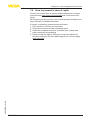
7 Diagnosis, asset management and service
7.1Maintenance................................................................................................................... 39
7.2 Rectify faults.................................................................................................................... 39
7.3 Exchanging the electronics module................................................................................. 39
7.4 Exchange process assembly with version IP 68 (25 bar)................................................. 39
7.5 How to proceed in case of repair..................................................................................... 41
Contents
45050-EN-131011
9.1 Technical data................................................................................................................. 43
9.2Dimensions..................................................................................................................... 51
Safety instructions for Ex areas
Please note the Ex-specific safety information for installation and operation in Ex areas. These safety instructions are part of the operating
instructions manual and come with the Ex-approved instruments.
Editing status: 2013-10-09
VEGABAR 82 • Slave sensor for electronic differential pressure
3
1 About this document
1 About this document
1.1Function
This operating instructions manual provides all the information you
need for mounting, connection and setup as well as important instructions for maintenance and fault rectification. Please read this information before putting the instrument into operation and keep this manual
accessible in the immediate vicinity of the device.
1.2 Target group
This operating instructions manual is directed to trained specialist
personnel. The contents of this manual should be made available to
these personnel and put into practice by them.
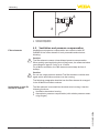
1.3 Symbolism used
Information, tip, note
This symbol indicates helpful additional information.
Caution: If this warning is ignored, faults or malfunctions can result.
Warning: If this warning is ignored, injury to persons and/or serious
damage to the instrument can result.
Danger: If this warning is ignored, serious injury to persons and/or
destruction of the instrument can result.
•
→
1
Ex applications
This symbol indicates special instructions for Ex applications.
List
The dot set in front indicates a list with no implied sequence.
Action
This arrow indicates a single action.
Sequence of actions
Numbers set in front indicate successive steps in a procedure.
Battery disposal
This symbol indicates special information about the disposal of batteries and accumulators.
45050-EN-131011
4
VEGABAR 82 • Slave sensor for electronic differential pressure
2 For your safety
2 For your safety
2.1 Authorised personnel
All operations described in this operating instructions manual must
be carried out only by trained specialist personnel authorised by the
plant operator.
During work on and with the device the required personal protective
equipment must always be worn.
2.2 Appropriate use
VEGABAR 82 is a slave sensor for electronic differential pressure
measurement.
You can find detailed information on the application range in chapter
"Product description".
Operational reliability is ensured only if the instrument is properly
used according to the specifications in the operating instructions
manual as well as possible supplementary instructions.
2.3 Warning about incorrect use
Inappropriate or incorrect use of the instrument can give rise to
application-specific hazards, e.g. vessel overfill or damage to system
components through incorrect mounting or adjustment.
2.4 General safety instructions
This is a high-tech instrument requiring the strict observance of standard regulations and guidelines. The user must take note of the safety
instructions in this operating instructions manual, the country-specific
installation standards as well as all prevailing safety regulations and
accident prevention rules.
The instrument must only be operated in a technically flawless and
reliable condition. The operator is responsible for trouble-free operation of the instrument.
During the entire duration of use, the user is obliged to determine the
compliance of the necessary occupational safety measures with the
current valid rules and regulations and also take note of new regulations.
2.5 CE conformity
45050-EN-131011
The device fulfills the legal requirements of the applicable EC guidelines. By affixing the CE marking, we confirm successful testing of the
product.
You can find the CE Certificate of Conformity in the download section
of our homepage.
VEGABAR 82 • Slave sensor for electronic differential pressure
5
2 For your safety
2.6 Measuring range - permissible process
pressure
The permissible process pressure is specified on the type label with
"process pressure", see chapter "Configuration". For safety reasons,
this range must not be exceeded. This applies also if a measuring
cell with higher measuring range (order-related) than the permissible
pressure range of the process fitting is installed.
2.7 Environmental instructions
Protection of the environment is one of our most important duties.
That is why we have introduced an environment management system
with the goal of continuously improving company environmental protection. The environment management system is certified according
to DIN EN ISO 14001.
Please help us fulfill this obligation by observing the environmental
instructions in this manual:
•
•
Chapter "Packaging, transport and storage"
Chapter "Disposal"
45050-EN-131011
6
VEGABAR 82 • Slave sensor for electronic differential pressure
3 Product description
3 Product description
Type plate
3.1 Configuration
The nameplate contains the most important data for identification and
use of the instrument:
1
2
3
4
5
6
7
8
9
10
16
15
14
13
12
11
Fig. 1: Layout of the type label (example)
1 Instrument type
2 Product code
3 Field for approvals
4 Power supply and signal output, electronics
5 Protection rating
6 Measuring range
7 Permissible process pressure
8 Material, wetted parts
9 Hardware and software version
10 Order number
11 Serial number of the instrument
12 Symbol of the device protection class
13 ID numbers, instrument documentation
14 Reminder to observe the instrument documentation
15 Notified authority for CE marking
16 Approval directive
Serial number
The type label contains the serial number of the instrument. With it
you can find the following data on our homepage:
•
•
•
•
•
•
Product code of the instrument (HTML)
Delivery date (HTML)
Order-specific instrument features (HTML)
Operating instructions at the time of shipment (PDF)
Order-specific sensor data for an electronics exchange (XML)
Test certificate pressure transmitters (PDF)
45050-EN-131011
Go to www.vega.com, "VEGA Tools" and "Serial number search".
As an alternative, you can find the data via your Smartphone:
•
•
•
Download the smartphone app "VEGA Tools" from the "Apple App
Store" or the "Google Play Store"
Scan the Data Matrix code on the type label of the instrument or
Enter the serial number manually in the app
VEGABAR 82 • Slave sensor for electronic differential pressure
7
3 Product description
Scope of this operating
instructions manual
This operating instructions manual applies to the following instrument
versions:
Scope of delivery
The scope of delivery encompasses:
Electronic differential
pressure measurement
The VEGABAR 82 slave sensor is combined with a sensor from the
VEGABAR 80 series for electronic differential pressure measurement.
Measured variables
The electronic differential pressure measurement is suitable for the
measurement of the following process variables:
•
•
•
•
•
•
Hardware from 1.0.0
Software version from 1.0.0
VEGABAR 82 pressure transmitter
Connection cable to the master sensor
Cable gland for the master sensor
Documentation
–– this operating instructions manual
–– Test certificate measuring accuracy (optional)
–– Supplementary instructions manual "Plug connector for continuously measuring sensors" (optional)
–– Ex-specific "Safety instructions" (with Ex versions)
–– if necessary, further certificates
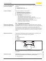
3.2 Principle of operation
The sensors are connected via a screened four-wire cable. The
measured value from the slave sensor is read in and factored into the
calculations. Parameter adjustment is carried out through the master
sensor.
•
•
•
•
•
Level
Flow
Differential pressure
Density
Interface
Application area
VEGABAR 82 is suitable for applications in virtually all industries. It is
used for the measurement of the following pressure types.
•
8
Gauge pressure
VEGABAR 82 • Slave sensor for electronic differential pressure
45050-EN-131011
Fig. 2: Electronic differential pressure measurement through Master/Slave
combination
3 Product description
•
•
Absolute pressure
Vacuum
Measured products
Measured products are gases, vapours and liquids.
Measuring system
Sensor element is the CERTEC® measuring cell with robust ceramic
diaphragm. The process pressure deflects the ceramic diaphragm
and causes a capacitance change in the measuring cell. This capacitance change is converted into an electrical signal and outputted as
measured value via the output signal.
Depending on the process fitting and measurement setup, measured
products can be also viscous or contain abrasive substances.
The CERTEC® measuring cell is available in two sizes:
•
•
Pressure types
ø 17.5 mm with small process fittings
ø 28 mm with large process fittings as well as all flange connections
The measuring cell design depends on the selected pressure type.
Relative pressure: the measuring cell is open to atmosphere. The
ambient pressure is detected in the measuring cell and compensated.
It thus has no influence on the measured value.
Absolute pressure: the measuring cell is evacuated and encapsulated. The ambient pressure is not compensated and does hence
influence the measured value.
Relative pressure, climate-compensated: the measuring cell is
evacuated and encapsulated. The ambient pressure is detected
through a reference sensor in the electronics and compensated. It
thus has no influence on the measured value.
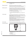
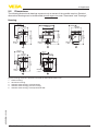
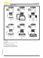
Seal concepts
Recessed installation
The following presentations show the installation of the CERTEC®
measuring cell into the process fitting and the different seal concepts.
1
2
3
4
45050-EN-131011
5
Fig. 3: Recessed installation of the CERTEC® measuring cell
1
2
3
4
5
Measuring cell
Seal for the measuring cell
Diaphragm
Process fitting
Seal for the process fitting
VEGABAR 82 • Slave sensor for electronic differential pressure
9
3 Product description
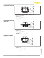
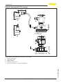
Front-flush mounting with
single seal
1
2
3
4
5
Fig. 4: Front-flish mounting of the CERTEC® measuring cell
1
2
3
4
5
Seal for the process fitting
Measuring cell
Seal for the measuring cell
Process fitting
Diaphragm
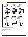
Front-flush mounting with
double seal
1
2
3
4
5
Fig. 5: Front-flush installation of the CERTEC® measuring cell with double seal
1
2
3
4
5
Measuring cell
Seal for the measuring cell
Process fitting
Additional, front seal for measuring cell
Diaphragm
Installation in hygienic
fitting
1
2
3
4
5
Fig. 6: Hygienic installation of the CERTEC® measuring cell
10
Measuring cell
Form seal for the measuring cell
Gap-free seal for process fitting
Process fitting
Diaphragm
VEGABAR 82 • Slave sensor for electronic differential pressure
45050-EN-131011
1
2
3
4
5
3 Product description
Packaging
3.3 Packaging, transport and storage
Your instrument was protected by packaging during transport. Its
capacity to handle normal loads during transport is assured by a test
based on ISO 4180.
The packaging of standard instruments consists of environmentfriendly, recyclable cardboard. For special versions, PE foam or PE
foil is also used. Dispose of the packaging material via specialised
recycling companies.
Transport
Transport must be carried out in due consideration of the notes on the
transport packaging. Nonobservance of these instructions can cause
damage to the device.
Transport inspection
The delivery must be checked for completeness and possible transit
damage immediately at receipt. Ascertained transit damage or concealed defects must be appropriately dealt with.
Storage
Up to the time of installation, the packages must be left closed and
stored according to the orientation and storage markings on the
outside.
Unless otherwise indicated, the packages must be stored only under
the following conditions:
Storage and transport
temperature
Protective cap
•
•
•
•
•
•
•
Not in the open
Dry and dust free
Not exposed to corrosive media
Protected against solar radiation
Avoiding mechanical shock and vibration
Storage and transport temperature see chapter "Supplement Technical data - Ambient conditions"
Relative humidity 20 … 85 %
3.4 Accessories and replacement parts
The protective cover protects the sensor housing against soiling and
intense heat from solar radiation.
You will find additional information in the supplementary instructions
manual "Protective cover" (Document-ID 34296).
Flanges
Screwed flanges are available in different versions according to the
following standards: DIN 2501, EN 1092-1, BS 10, ANSI B 16.5,
JIS B 2210-1984, GOST 12821-80.
45050-EN-131011
You can find additional information in the supplementary instructions
manual "Flanges according to DIN-EN-ASME-JIS" (Document-ID
31088).
Welded socket
Welded sockets are used to connect the sensors to the process.
You can find further information in the supplementary instructions
"Welded socket VEGABAR series 80" (Document-ID 45082).
VEGABAR 82 • Slave sensor for electronic differential pressure
11
3 Product description
Electronics module
The electronics module VEGABAR series 80 is a replacement part
for pressure transmitters of VEGABAR series 80. There is a different
version available for each type of signal output.
You can find further information in the operating instructions "Electronics module VEGABAR series 80" (Document-ID 45054).
45050-EN-131011
12
VEGABAR 82 • Slave sensor for electronic differential pressure
4 Mounting
4Mounting
4.1 General instructions to use the instrument
Suitability for the process Make sure that all parts of the instrument exposed to the process are
conditions
suitable for the existing process conditions.
These are mainly:
•
•
•
Active measuring component
Process fitting
Process seal
•
•
•
•
Process pressure
Process temperature
Chemical properties of the medium
Abrasion and mechanical influences
Process conditions are particularly:
You can find the specifications of the process conditions in chapter
"Technical data" as well as on the nameplate.
Protection against moisture
Protect your instrument further through the following measures
against moisture penetration:
•
•
•
Use the recommended cable (see chapter "Connecting to power
supply")
Tighten the cable gland
Loop the connection cable downward in front of the cable gland
This applies particularly to:
•
•
•
Screwing in
Outdoor mounting
Installations in areas where high humidity is expected (e.g. through
cleaning processes)
Installations on cooled or heated vessels
On instruments with process fitting thread, the hexagon must be tightened with a suitable screwdriver. Wrench size see chapter "Dimensions".
45050-EN-131011
Warning:
The housing must not be used to screw the instrument in! Applying
tightening force can damage internal parts of the housing.
Vibrations
In case of strong vibrations at the mounting location, the instrument
version with external housing should be used. See chapter "External
housing".
Temperature limits
Higher process temperatures often mean also higher ambient
temperatures. Make sure that the upper temperature limits stated in
chapter "Technical data" for the environment of the electronics housing and connection cable are not exceeded.
VEGABAR 82 • Slave sensor for electronic differential pressure
13
4 Mounting
2
1
Fig. 7: Temperature ranges
1 Process temperature
2 Ambient temperature
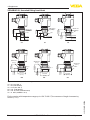
Filter elements
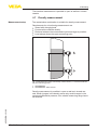
4.2 Ventilation and pressure compensation
Ventilation and pressure compensation are carried out with VEGABAR 82 via a filter element. It is air permeable and moistureblocking.
Caution:
The filter element causes a time-delayed pressure compensation.
When quickly opening/closing the housing cover, the measured value
can change for approx. 5 s by up to 15 mbar.
For effective ventilation, the filter element must always be free of
buildup.
Caution:
Do not use a high-pressure cleaner. The filter element could be damaged, which would allow moisture into the housing.
The following paragraphs describe how the filter element is arranged
in the different instrument versions.
Instruments in non-Ex
and Ex-ia version
The filter element is mounted into the electronics housing. It has the
following functions:
•
•
Ventilation electronics housing
Atmospheric pressure compensation (with relative pressure measuring ranges)
45050-EN-131011
14
VEGABAR 82 • Slave sensor for electronic differential pressure
4 Mounting
4
4
1
4
2
3
Fig. 8: Position of the filter element - non-Ex, Ex-ia version
1
2
3
4
Housing plastic, stainless steel precision casting
Housing aluminium
Housing stainless steel, electropolished
Filter element
With the following instruments a blind plug is installed instead of the
filter element:
•
•
Instruments in Ex-d version
Instruments in protection IP 66/IP 68 (1 bar) - ventilation via capillaries in fix connected cable
Instruments with absolut pressure
The filter element is integrated in the process assembly. It is located in
a rotatable metal ring and has the following functions:
•
Atmospheric pressure compensation (with relative pressure measuring ranges)
Turn the metal ring in such a way that the filter element points downward after installtion of the instrument. This provides better protection
against buildup.
1
2
Fig. 9: Position of the filter element - Ex-d version
1 Single chamber housing, aluminium, stainless steel precision casting
2 Rotatable metal ring
3 Filter element
45050-EN-131011
With absolute pressure measuring ranges, a blind plug is used
instead of the filter element.
Instruments with Second
Line of Defense
The filter element is mounted into the electronics housing. It has the
following functions:
•
•
Ventilation electronics housing
Atmospheric pressure compensation (with relative pressure measuring ranges)
VEGABAR 82 • Slave sensor for electronic differential pressure
15
4 Mounting
The process assembly of instruments with Second Line of Defense
(gastight leadthrough) is completely encapsulated. An absolute pressure measuring cell is used so that no ventilation is required.
1
1
Fig. 10: Position of the filter element - gastight leadthrough
1 Filter element
With relative pressure measuring ranges, the ambient pressure is
detected and compensated by a reference sensor in the electronics.
Instruments in IP 69K
version
The filter element is mounted into the electronics housing. It has the
following functions:
•
•
Ventilation electronics housing
Atmospheric pressure compensation (with relative pressure measuring ranges)
1
Fig. 11: Position of the filter element - IP 69K version
1 Filter element
Instruments with absolute pressure have a blind plug mounted
instead of the filter element.
4.3 Combination Master - Slave
In principle, any sensor combination within the VEGABAR 80 series is
allowed. The following requirements must be fulfilled:
•
•
•
16
VEGABAR 82 • Slave sensor for electronic differential pressure
45050-EN-131011
•
Configuration, Master sensor suitable for electronic differential
pressure
Pressure type is identical for both sensors, i.e. relative pressure/
relative pressure or absolute pressure/absolute pressure
The master sensor must always measure the higher pressure
Measurement setup as shown in the following chapters
4 Mounting
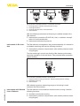
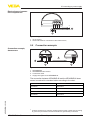
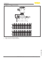
Measurement setup
4.4 Level measurement
The master/slave combination is suitable for level measurement in a
pressurized vessel
Keep the following in mind when setting up the measuring system:
•
•
•
•
Mount the master sensor below the min. level
Do not mount the master sensor close to the filling stream or
emptying area
Mount the master sensor so that it is protected against pressure
shocks from the stirrer
Mount the slave sensor above the max. level
2
1
Fig. 12: Measurement setup, level measurement in pressurized vessel
1 VEGABAR 82
1 VEGABAR 82 - Slave sensor
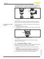
Measurement setup
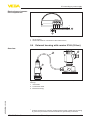
4.5 Differential pressure measurement
The master/slave combination is suitable for differential pressure
measurement
45050-EN-131011
Take note of the following instructions for the measurement setup, for
example in gases:
•
Mount the instruments above the measuring point
Possible condensation can then drain off into the process line.
VEGABAR 82 • Slave sensor for electronic differential pressure
17
4 Mounting
2
1
Fig. 13: Measurement setup for differential pressure measurement of gases in
pipelines
1 VEGABAR 82
1 VEGABAR 82 - Slave sensor
Measurement setup
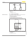
4.6 Interface measurement
The master/slave combination is suitable for interface measurement
Requirements for a functioning measurement are:
•
•
•
•
Vessel with changing level
Products with steady densities
Interface always between the measurement points
Total level always above the upper measurement point
2
h
0,8
1,0
1
1 VEGABAR 82
2 VEGABAR 82 - Slave sensor
18
VEGABAR 82 • Slave sensor for electronic differential pressure
45050-EN-131011
Fig. 14: Measurement setup with interface measurement, h = distance between
the two measuring points
4 Mounting
The interface measurement is possible in open as well as in closed
vessels.
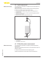
4.7 Density measurement
Measurement setup
The master/slave combination is suitable for density measurement.
Requirements for a functioning measurement are:
•
•
•
•
Vessel with changing level
Product with consistent density
Distance between the measurement points as large as possible
Level always above the upper measuring point
h
2
1
Fig. 15: Measurement setup with density measurement, h = distance between
the two measuring points
1 VEGABAR 82
2 VEGABAR 82 - Slave sensor
45050-EN-131011
Density measurement is possible in open as well as in closed vessels. Small changes in the density cause only small changes in the
measured differential pressure. So a suitable measuring range has to
be selected.
VEGABAR 82 • Slave sensor for electronic differential pressure
19
4 Mounting
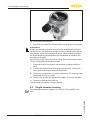
Configuration
4.8 External housing
4
3
2
5
1
Fig. 16: Setup process assembly, external housing
1
2
3
4
Mounting
Process assembly
Connection cable process assembly - External housing
External housing
Signal cable
1. Mark the holes according to the following drilling template
2. Fasten wall mounting plate with 4 screws
90 mm
(3.54")
70 mm
(2.76")
3mm
(0.12")
mm
3,5 4")
.1
0
(
93 mm
(3.66")
110 mm
(4.33")
R
8 mm
(0.32")
Fig. 17: Drilling template - wall mounting plate
45050-EN-131011
20
VEGABAR 82 • Slave sensor for electronic differential pressure
5 Connecting to power supply
5 Connecting to power supply
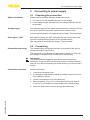
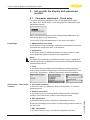
Safety instructions
Voltage supply
5.1 Preparing the connection
Always keep in mind the following safety instructions:
•
•
Connect only in the complete absence of line voltage
If overvoltage surges are expected, overvoltage arresters should
be installed
The voltage supply and the signal transmission are carried out via the
four-wire, screened connection cable from the master sensor.
You can find the data for this signal circuit in chapter "Technical data".
Cable gland ½ NPT
With plastic housing, the NPT cable gland or the Conduit steel tube
must be screwed without grease into the threaded insert.
Max. torque for all housings see chapter "Technical data".
Connection technology
5.2Connecting
The voltage supply and signal output are connected via the springloaded terminals in the housing.
The connection to the display and adjustment module or to the interface adapter is carried out via contact pins in the housing.
Information:
The terminal block is pluggable and can be removed from the
electronics. To do this, lift the terminal block with a small screwdriver
and pull it out. When reinserting the terminal block, you should hear it
snap in.
Connection procedure
Proceed as follows:
1. Unscrew the housing cover
2. If a display and adjustment module is installed, remove it by turning it slightly to the left.
3. Loosen compression nut of the cable entry
4. Remove approx. 10 cm (4 in) of the cable mantle, strip approx.
1 cm (0.4 in) of insulation from the ends of the individual wires
45050-EN-131011
5. Insert the cable into the sensor through the cable entry
VEGABAR 82 • Slave sensor for electronic differential pressure
21
5 Connecting to power supply
Fig. 18: Connection steps 5 and 6
6. Insert the wire ends into the terminals according to the wiring plan
Information:
Solid cores as well as flexible cores with wire end sleeves are inserted directly into the terminal openings. In case of flexible cores without
end sleeves, press the terminal from above with a small screwdriver;
the terminal opening is freed. When the screwdriver is released, the
terminal closes again.
You can find further information on the max. wire cross-section under
"Technical data/Electromechanical data"
7. Check the hold of the wires in the terminals by lightly pulling on
them
8. Connect the screen to the internal ground terminal, connect the
outer ground terminal to potential equalisation
9. Tighten the compression nut of the cable entry. The seal ring must
completely encircle the cable
10. Reinsert the display and adjustment module, if one was installed
11. Screw the housing cover back on
The electrical connection is hence finished.
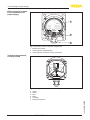
5.3 Single chamber housing
The following illustration applies to the non-Ex, Ex-ia and Ex-d version.
45050-EN-131011
22
VEGABAR 82 • Slave sensor for electronic differential pressure
5 Connecting to power supply
Electronics and connection compartment
Master
5
6
7
8
4
1
2
Fig. 19: Wiring plan VEGABAR 82 Slave sensor
1 To the sensor
2 Ground terminal for connection of the cable screen1)
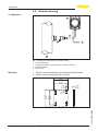
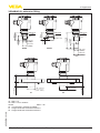
Overview
5.4 External housing with version IP 68 (25 bar)
2
3
1
Fig. 20: VEGABAR 82 in IP 68 version 25 bar with axial cable outlet, external
housing
45050-EN-131011
1 Transmitter
2 Connection cable
3 External housing
1)
Connect screen here. Connect ground terminal on the outside of the housing
to ground as prescribed. The two terminals are galvanically connected.
VEGABAR 82 • Slave sensor for electronic differential pressure
23
5 Connecting to power supply
Electronics and connection compartment for
power supply
1
4...20mA
(+)1
2(-)
5
6
7
8
2
3
Fig. 21: Electronics and connection compartment
1 Electronics module
2 Cable gland for voltage supply
3 Cable gland for connection cable, transmitter
Terminal compartment,
housing socket
1 2 3 4
1
5
2
3
4
6
Fig. 22: Connection of the sensor in the housing base
24
Yellow
White
Red
Black
Shielding
Breather capillaries
VEGABAR 82 • Slave sensor for electronic differential pressure
45050-EN-131011
1
2
3
4
5
6
5 Connecting to power supply
Electronics and connection compartment
Master
5
6
7
8
4
1
2
Fig. 23: Wiring plan VEGABAR 82 Slave sensor
1 To the sensor
2 Ground terminal for connection of the cable screen2)
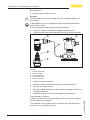
Connection example,
slave sensor
5.5 Connection example
4...20mA
(+)1
2(-)
5
6
7
8
4
3
5
6
7
8
4
1
2
Fig. 24: Connection example VEGABAR 82 slave sensor
1
2
3
4
VEGABAR 82
VEGABAR 82 slave sensor
Connection cable
Supply and signal circuit VEGABAR 82
45050-EN-131011
The connection between VEGABAR 82 and the VEGABAR 82 slave
sensor is made with a standard cable according to the chart:
VEGABAR 82
Slave sensor
Terminal 5
Terminal 5
Terminal 6
Terminal 6
Terminal 7
Terminal 7
Terminal 8
Terminal 8
2)
Connect screen here. Connect ground terminal on the outside of the housing
to ground as prescribed. The two terminals are galvanically connected.
VEGABAR 82 • Slave sensor for electronic differential pressure
25
6 Set up with the display and adjustment module
6 Set up with the display and adjustment
module
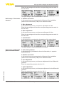
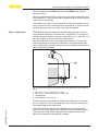
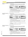
6.1 Parameter adjustment - Quick setup
To quickly and easily adapt the sensor to the application, select
the menu item "Quick setup" in the start graphic on the display and
adjustment module.
Carry out the following steps in the sequence specified below. The
presettings apply to all applications.
You can find "Extended adjustment" in the next sub-chapter.
Presettings
1. Measurement loop name
In the first menu item you assign a suitable measurement loop name.
Permitted are names with max. 19 characters.
2. Application
In this menu item you activate/deactivate the slave sensor for electronic differential pressure and select the application.
Note:
It is absolutely necessary to activate the slave sensor in advance to
have the applications displayed in the electronic differential pressure
measurement menus.
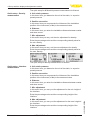
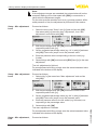
3. Units
In this menu item you determine the adjustment and temperature
units of the instrument. Depending on the selected application in the
menu item "Application", different adjustment units are available.
Quick setup - Level meas- 4. Unit, static pressure
urement
In this menu item, you determine the unit of the static, i.e. superimposed pressure.
5. Position correction
In this menu item you compensate the influence of the installation
position of the instrument (offset) to the measured value.
Enter the percentage value and the corresponding pressure value for
the min. level.
7. Max. adjustment
In this menu item you carry out the max. adjustment for level.
26
VEGABAR 82 • Slave sensor for electronic differential pressure
45050-EN-131011
6. Min. adjustment
In this menu item you carry out the min. adjustment for level.
6 Set up with the display and adjustment module
Enter the percentage value and the corresponding pressure value for
the max. level.
The quick setup for level measurement is finished.
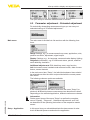
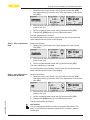
Quick setup - Flow measurement
4. Position correction
In this menu item you compensate the influence of the installation
position of the instrument (offset) to the measured value.
5. Min. adjustment
In this menu item you carry out the min. adjustment for flow.
Enter the percentage value and the corresponding pressure value for
the min. flow.
6. Max. adjustment
In this menu item you carry out the max. adjustment for flow.
Enter the percentage value and the corresponding pressure value for
the max. flow.
7. Linearization
In this menu item, you select the characterics of the output signal.
The quick setup for flow measurement is finished.
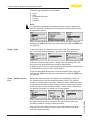
Quick setup - Differential
pressure measurement
4. Unit, static pressure
In this menu item, you determine the unit of the static, i.e. superimposed pressure.
5. Position correction
In this menu item you compensate the influence of the installation
position of the instrument (offset) to the measured value.
6. zero adjustment
In this menu item you carry out the zero adjustment for the differential
pressure.
Enter the respective pressure value for 0 %.
45050-EN-131011
7. span adjustment
In this menu item you carry out the span adjustment for the differential
pressure
Enter the respective pressure value for 100 %.
VEGABAR 82 • Slave sensor for electronic differential pressure
27
6 Set up with the display and adjustment module
The quick setup for differential pressure measurement is finished.
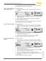
Quick setup - Density
measurement
4. Unit, static pressure
In this menu item, you determine the unit of the static, i.e. superimposed pressure.
5. Position correction
In this menu item you compensate the influence of the installation
position of the instrument (offset) to the measured value.
6. Distance
In this menu item, you enter the installation distance between master
and slave sensor.
7. Min. adjustment
In this menu item you carry out the min. adjustment for density.
Enter the percentage value and the corresponding density value for
the min. density.
8. Max. adjustment
In this menu item you carry out the max. adjustment for density.
Enter the percentage value and the corresponding density value for
the max. density.
The quick setup for density measurement is finished.
Quick setup - Interface
measurement
4. Unit, static pressure
In this menu item, you determine the unit of the static, i.e. superimposed pressure.
5. Position correction
In this menu item you compensate the influence of the installation
position of the instrument (offset) to the measured value.
6. Distance
In this menu item, you enter the installation distance between master
and slave sensor.
7. Min. adjustment
In this menu item, you carry out the adjustment for the min. height of
the interface.
Enter the percentage value and the corresponding height of the
interface.
Enter the percentage value and the corresponding height of the
interface.
28
VEGABAR 82 • Slave sensor for electronic differential pressure
45050-EN-131011
8. Max. adjustment
In this menu item, you carry out the adjustment for the max. height of
the interface.
6 Set up with the display and adjustment module
The quick setup for interface measurement is finished.
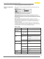
6.2 Parameter adjustment - Extended adjustment
For technically demanding measurement loops you can carry out
extended settings in "Extended adjustment".
Main menu
The main menu is divided into five sections with the following functions:
Setup: Settings, e.g., for measurement loop name, application, units,
position correction, adjustment, signal output
Display: Settings, e.g., for language, measured value display, lighting
Diagnosis: Information, e.g. on instrument status, pointer, measurement reliability, simulation
Additional adjustments: PIN, date/time, reset, copy function
Info: Instrument name, hardware and software version, date of manufacture, sensor features
In the main menu item "Setup", the individual submenu items should
be selected one after the other and provided with the correct parameter values.
The following submenu points are available:
45050-EN-131011
In the following section, the menu items from the menu "Setup" for
electronic differential pressure measurement are described in detail.
Depending on the selected application, different sections are relevant.
Information:
Further menu items of the menu "Setup" as well as the complete
menus "Display", "Diagnosis", "Additional adjustments" and "Info"
are described in the operating instructions of the respective master
sensor.
Setup - Application
In this menu item you activate/deactivate the slave sensor for electronic differential pressure and select the application.
VEGABAR 82 • Slave sensor for electronic differential pressure
29
6 Set up with the display and adjustment module
The following applications are available:
•
•
•
•
•
Level
Flow
Differential pressure
Density
Interface
Note:
It is absolutely necessary to activate the slave sensor in advance to
have the applications displayed in the electronic differential pressure
measurement menus.
Enter the requested parameters via the appropriate keys, save your
settings with [OK] and jump to the next menu item with the [ESC] and
the [->] key.
Setup - Units
In this menu item, you determine the units for the "Min. adjustment/
zero" and "Max. adjustment/span" as well as the static pressure.
If the level should be adjusted in a height unit, the density of the medium must also be entered later during the adjustment.
In addition, the unit for the measuring cell and electronics temperature
is determined in the menu item "Peak values".
Enter the requested parameters via the appropriate keys, save your
settings with [OK] and jump to the next menu item with the [ESC] and
the [->] key.
Setup - Position correction
Particularly with chemical seal systems, the installation position of
the instrument can shift the measured value (offset). The position
correction compensates this offset. Hence the actual measured value
is accepted automatically. With relative pressure measuring cells also
a manual offset can be carried out. With a master/slave combination,
the position correction is carried out for both sensors.
With the manual position correction, the offset value can be determined by the user. Select for this purpose the function "Edit" and
enter the requested value.
30
VEGABAR 82 • Slave sensor for electronic differential pressure
45050-EN-131011
If the actual measured value should be taken over as correction value
during automatic position correction, this value must not be influenced by product coverage or static pressure.
6 Set up with the display and adjustment module
Save your settings with [OK] and move with [ESC] and [->] to the
next menu item.
After the position correction is carried out, the actual measured value
is corrected to 0. The corrective value appears with an inverse sign as
offset value in the display.
The position correction can be repeated as often as necessary. However, if the sum of the corrective values exceeds 20 % of the nominal
measuring range, then no position correction is possible.
Setup - Adjustment
VEGABAR 82 always measures pressure independently of the process variable selected in the menu item "Application". To output the
selected process variable correctly, an allocation to 0 % and 100 % of
the output signal must be carried out (adjustment).
With the application "Level", the hydrostatic pressure, e.g. with full
and empty vessel, is entered for adjustment. A superimposed pressure is detected by the slave sensor and automatically compensated.
See the following example:
4
2
5m
(196.9")
100%
0%
1
3
Fig. 25: Parameter adjustment example "Min./max. adjustment, level measurement"
1
2
3
4
Min. level = 0 % corresponds to 0.0 mbar
Max. level = 100 % corresponds to 490.5 mbar
VEGABAR 82
VEGABAR 82 - Slave sensor
45050-EN-131011
If these values are not known, an adjustment with levels of for example 10 % and 90 % is also possible. By means of these settings, the
real filling height is then calculated.
The real product level during this adjustment is not important, because the min./max. adjustment is always carried out without changing the product level. These settings can be made ahead of time
without the instrument having to be installed.
VEGABAR 82 • Slave sensor for electronic differential pressure
31
6 Set up with the display and adjustment module
Note:
If the adjustment ranges are exceeded, the entered value will not be
accepted. Editing can be interrupted with [ESC] or corrected to a
value within the adjustment ranges.
For the other process variables such as e.g. process pressure, differential pressure or flow, the adjustment is performed in like manner.
Setup - Min. adjustment
Level
Proceed as follows:
1. Select the menu item "Setup" with [->] and confirm with [OK].
Now select with [->] the menu item "Adjustment", then "Min.
adjustment" and confirm with [OK].
2. Edit the percentage value with [OK] and set the cursor to the
requested position with [->].
3. Set the requested percentage value (e.g. 10 %) with [+] and save
with [OK]. The cursor jumps now to the pressure value.
4. Enter the pressure value corresponding to the min. level (e.g.
0 mbar).
5. Save settings with [OK] and move with [ESC] and [->] to the max.
adjustment.
The min. adjustment is finished.
For an adjustment with filling, simply enter the actual measured value
indicated at the bottom of the display.
Setup - Max. adjustment
Level
Proceed as follows:
1. Select with [->] the menu item "Max. adjustment" and confirm
with [OK].
2. Edit the percentage value with [OK] and set the cursor to the
requested position with [->].
3. Set the requested percentage value (e.g. 90 %) with [+] and save
with [OK]. The cursor jumps now to the pressure value.
4. Enter the pressure value for the full vessel (e.g. 900 mbar) corresponding to the percentage value.
5. Save settings with [OK]
For an adjustment with filling, simply enter the actual measured value
indicated at the bottom of the display.
Setup - Min. adjustment,
flow
32
Proceed as follows:
VEGABAR 82 • Slave sensor for electronic differential pressure
45050-EN-131011
The max. adjustment is finished.
6 Set up with the display and adjustment module
1. Select the menu item "Setup" with [->] and confirm with [OK].
Now select with [->] the menu item "Min. adjustment" and confirm
with [OK].
2. Edit the mbar value with [OK] and set the cursor to the requested
position with [->].
3. Set the requested mbar value with [+] and store with [OK].
4. Change with [ESC] and [->] to the span adjustment
The min. adjustment is finished.
For an adjustment with pressure, simply enter the actual measured
value indicated at the bottom of the display.
Setup - Max. adjustment,
flow
Proceed as follows:
1. Select with [->] the menu item "Max. adjustment" and confirm
with [OK].
2. Edit the mbar value with [OK] and set the cursor to the requested
position with [->].
3. Set the requested mbar value with [+] and store with [OK].
The max. adjustment is finished.
For an adjustment with pressure, simply enter the actual measured
value indicated at the bottom of the display.
Setup - zero adjustment,
differential pressure
Proceed as follows:
1. Select the menu item "Setup" with [->] and confirm with [OK].
Now select with [->] the menu item "zero adjustment" and confirm
with [OK].
2. Edit the mbar value with [OK] and set the cursor to the requested
position with [->].
3. Set the requested mbar value with [+] and store with [OK].
45050-EN-131011
4. Change with [ESC] and [->] to the span adjustment
The zero adjustment is finished.
Information:
The zero adjustment shifts the value of the span adjustment. The
span, i.e. the difference between these values, however, remains
unchanged.
VEGABAR 82 • Slave sensor for electronic differential pressure
33
6 Set up with the display and adjustment module
For an adjustment with pressure, simply enter the actual measured
value indicated at the bottom of the display.
Setup - span adjustment,
differential pressure
Proceed as follows:
1. Select with [->] the menu item "Span adjustment" and confirm
with [OK].
2. Edit the mbar value with [OK] and set the cursor to the requested
position with [->].
3. Set the requested mbar value with [+] and store with [OK].
The span adjustment is finished.
For an adjustment with pressure, simply enter the actual measured
value indicated at the bottom of the display.
Setup - Distance, density
Proceed as follows:
1. Select the menu item "Setup" with [->] and confirm with [OK].
Now select with [->] the menu item "Distance" and confirm with
[OK].
2. Edit the sensor distance with [OK] and set the cursor to the
requested position with [->].
3. Set the requested distance with [+] and store with [OK].
The adjustment of the distance is hence finished.
Setup - Min. adjustment,
density
Proceed as follows:
1. Select the menu item "Setup" with [->] and confirm with [OK].
Now select with [->] the menu item "Min. adjustment" and confirm
with [OK].
2. Edit the percentage value with [OK] and set the cursor to the
requested position with [->].
4. Enter the min. distance suitable for the percentage value.
5. Save settings with [OK] and move with [ESC] and [->] to the max.
adjustment.
The min. adjustment for density is finished.
34
VEGABAR 82 • Slave sensor for electronic differential pressure
45050-EN-131011
3. Set the requested percentage value with [+] and save with [OK].
The cursor jumps now to the density value.
6 Set up with the display and adjustment module
Setup - Max. adjustment,
density
Proceed as follows:
1. Select the menu item "Setup" with [->] and confirm with [OK].
Now select with [->] the menu item "Max. adjustment" and confirm with [OK].
2. Edit the percentage value with [OK] and set the cursor to the
requested position with [->].
3. Set the requested percentage value with [+] and save with [OK].
The cursor jumps now to the density value.
4. Enter the max. density value matching the percentage value.
The max. adjustment for density is finished.
Setup - Min. adjustment Interface
Proceed as follows:
1. Select the menu item "Setup" with [->] and confirm with [OK].
Now select with [->] the menu item "Min. adjustment" and confirm
with [OK].
2. Edit the percentage value with [OK] and set the cursor to the
requested position with [->].
3. Set the requested percentage value with [+] and save with [OK].
The cursor jumps now to the height value.
4. Enter the min. height of the interface suitable for the percentage
value.
5. Save settings with [OK] and move with [ESC] and [->] to the max.
adjustment.
The min. adjustment, interface is hence finished.
45050-EN-131011
Setup - Max. adjustment - Proceed as follows:
Interface
1. Select the menu item "Setup" with [->] and confirm with [OK].
Now select with [->] the menu item "Max. adjustment" and confirm with [OK].
2. Edit the percentage value with [OK] and set the cursor to the
requested position with [->].
3. Set the requested percentage value with [+] and save with [OK].
The cursor jumps now to the height value.
4. Enter the max. height of the interface matching the percentage
value.
VEGABAR 82 • Slave sensor for electronic differential pressure
35
6 Set up with the display and adjustment module
The max. adjustment for interface is finished.
Additional adjustments
- Reset
With a reset, certain parameter adjustments carried out by the user
are reset.
The following reset functions are available:
Delivery status: Restoring the parameter settings at the time of
shipment from the factory incl. the order-specific settings. A user-programmable linearization curve as well as the measured value memory
will be deleted.
Basic settings: Resetting the parameter settings incl. special
parameters to the default values of the respective instrument. A user
programmable linearization curve as well as the measured value
memory is deleted.
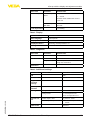
The following table shows the default values of the instrument. Depending on the instrument version or application, all menu items may
not be available or some may be differently assigned:
Reset - Setup
Menu item
Parameter
Sensor
Measurement
loop name
Application
Units
Slave for electronic differential
pressure
No reset
Application
No reset
Unit of measurement
mbar (with nominal measuring range
≤400 mbar)
Static pressure
bar
bar (with nominal measuring ranges ≥1 bar)
0.00 bar
Position correction
Adjustment
Default value
Distance (with
density and interface)
1.00 m
Zero/Min. adjustment
0.00 bar
0.00 %
Damping
Linearization
36
Integration time
0.0 s
Linear
VEGABAR 82 • Slave sensor for electronic differential pressure
45050-EN-131011
Span/Max. adjust- Nominal measuring range in bar
ment
100.00 %
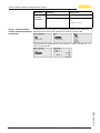
6 Set up with the display and adjustment module
Menu item
Parameter
Default value
Current output
Current output Mode
Output characteristics
4 … 20 mA
Reaction when malfunction occurs
≤ 3.6 mA
Current output Min./Max.
3.8 mA
20.5 mA
Last setting
Lock adjustment
Reset - Display
Menu item
Default value
Menu language
Order-specific
Displayed value 1
Current output in %
Displayed value 2
Measuring cell temperature in °C
Backlight
Switched off
Reset - Diagnosis
Menu item
Parameter
Peak value
Default value
-
Sensor status
Pressure
Actual measured value
Temperature
Actual temperature values from measuring cell, electronics
-
Simulation
Reset - Additional settings
Menu item
Default value
0000
Date/Time
Actual date/Actual time
Copy instrument
settings
-
Special parameters
No reset
Scaling
45050-EN-131011
Parameter
PIN
Current output
Scaling size
Volume in l
Scaling format
0 % corresponds to 0 l
Current output - Size
Lin. percent - Level
Current output - adjustment
0 … 100 % correspond to
4 … 20 mA
HART mode
VEGABAR 82 • Slave sensor for electronic differential pressure
100 % corresponds to 0 l
Address 0
37
6 Set up with the display and adjustment module
Menu item
Parameter
Default value
Effective
pressure
transmitter
Unit
m3/s
Adjustment
0.00 % correspond to 0.00
m3/s
100.00 %, 1 m3/s
Setup - Characteristics
In this menu item, the units for the effective pressure transmitter are
values, effective pressure determined as well as the selection of mass or volume flow.
transmitter
Furthermore the adjustment for the volume or mass flow rate at 0 % or
100 % is carried out.
45050-EN-131011
38
VEGABAR 82 • Slave sensor for electronic differential pressure
7 Diagnosis, asset management and service
7 Diagnosis, asset management and service
Maintenance
7.1Maintenance
If the instrument is used properly, no special maintenance is required
in normal operation.
In some applications, product buildup on the diaphragm can influence
the measuring result. Depending on the sensor and application, take
precautions to ensure that heavy buildup, and especially a hardening
thereof, is avoided.
7.2 Rectify faults
Reaction when malfunctions occur
The operator of the system is responsible for taking suitable measures to rectify faults.
Procedure for fault rectification
The first measures are:
•
•
•
Evaluation of fault messages, for example via the display and
adjustment module
Checking the output signal
Treatment of measurement errors
Further comprehensive diagnostics options are available with a PC
with PACTware and the suitable DTM. In many cases, the reasons can
be determined in this way and faults rectified.
Reaction after fault rectification
Depending on the reason for the fault and the measures taken, the
steps described in chapter "Setup" must be carried out again or must
be checked for plausibility and completeness.
24 hour service hotline
Should these measures not be successful, please call in urgent cases
the VEGA service hotline under the phone no. +49 1805 858550.
The hotline is also available outside normal working hours, seven
days a week around the clock.
Since we offer this service worldwide, the support is provided in
English. The service itself is free of charge, the only costs involved are
the normal call charges.
7.3 Exchanging the electronics module
In case of a defect, the user can replace the electronics module with
another one of identical type.
In Ex applications, only instruments and electronics modules with appropriate Ex approval may be used.
45050-EN-131011
If there is no electronics module available on site, one can be ordered
from the agency serving you.
7.4 Exchange process assembly with version
IP 68 (25 bar)
With version IP 68 (25 bar), the user can exchange the process assembly on site. Connection cable and external housing can be kept.
VEGABAR 82 • Slave sensor for electronic differential pressure
39
7 Diagnosis, asset management and service
Required tools:
•
Hexagon socket wrench, size 2
Caution:
The exchange may only be carried out in the complete absence of
line voltage.
In Ex applications, only a replacement part with appropriate Ex approval may be used.
Proceed as follows when carrying out the exchange:
1. Losen the fixing screw with the hexagon socket wrench
2. Carefully detach the cable assembly from the process assembly
3
5
4
2
1
Fig. 26: VEGABAR 82 in IP 68 version, 25 bar and lateral cable outlet, external
housing
1
2
3
4
5
Process assembly
Plug connector
Cable assembly
Connection cable
External housing
3. Loosen the plug connector
4. Mount the new process assembly on the measuring point
5. Plug the connector back in
6. Mount the cable assembly on the process assembly and turn it to
the desired position
7. Tighten the fixing screw with the hexagon socket wrench
The exchange is finished.
The necessary serial number can be found on the type label of the
instrument or on the delivery note.
40
VEGABAR 82 • Slave sensor for electronic differential pressure
45050-EN-131011
If there is no replacement part available on site, one can be ordered
from the agency serving you.
7 Diagnosis, asset management and service
7.5 How to proceed in case of repair
You can find a repair form as well as detailed information on how to
proceed under www.vega.com/downloads and "Forms and certificates".
By doing this you help us carry out the repair quickly and without having to call back for needed information.
If a repair is necessary, please proceed as follows:
•
•
•
45050-EN-131011
•
Print and fill out one form per instrument
Clean the instrument and pack it damage-proof
Attach the completed form and, if need be, also a safety data
sheet outside on the packaging
Please contact the agency serving you to get the address for
the return shipment. You can find the agency on our home page
www.vega.com.
VEGABAR 82 • Slave sensor for electronic differential pressure
41
8 Dismounting
8Dismounting
8.1 Dismounting steps
Warning:
Before dismounting, be aware of dangerous process conditions such
as e.g. pressure in the vessel or pipeline, high temperatures, corrosive or toxic products etc.
Take note of chapters "Mounting" and "Connecting to power supply"
and carry out the listed steps in reverse order.
8.2Disposal
The instrument consists of materials which can be recycled by specialised recycling companies. We use recyclable materials and have
designed the parts to be easily separable.
Correct disposal avoids negative effects on humans and the environment and ensures recycling of useful raw materials.
Materials: see chapter "Technical data"
If you have no way to dispose of the old instrument properly, please
contact us concerning return and disposal.
WEEE directive 2002/96/EG
This instrument is not subject to the WEEE directive 2002/96/EG and
the respective national laws. Pass the instrument directly on to a specialised recycling company and do not use the municipal collecting
points. These may be used only for privately used products according
to the WEEE directive.
45050-EN-131011
42
VEGABAR 82 • Slave sensor for electronic differential pressure
9 Supplement
9Supplement
9.1
Technical data
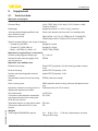
Materials and weights
Materials, wetted parts
Process fitting
Diaphragm
Joining material diaphragm/Basic element measuring cell
Measuring cell seal
316L, PVDF, Alloy C-22, Alloy C-276, Duplex 1.4462,
Titanium Grade 2
Sapphire-ceramic® (> 99.9 % Al2O3 ceramic)
Glass (with double and form seal, non-wetted parts)
FKM (VP2/A, A+P 70.16), EPDM (A+P 75.5/KW75F),
FFKM (Kalrez 6375, Perlast G75S, Perlast G75B)
Seal for process fitting (in the scope of delivery)
ƲƲ Thread G½ (EN 837)
Klingersil C-4400
ƲƲ M44 x 1.25 (DIN 13), M30 x 1.5
FKM, FFKM, EPDM
ƲƲ Thread G1½ (DIN 3852-A)
Klingersil C-4400
Materials for applications in foodstuffs
Surface quality hygienic fittings, typ.
Seal below wall mounting plage 316L
with 3A approval
Materials, non-wetted parts
Electronics housing
External housing
Socket, wall mounting plate external
housing
EPDM
Plastic PBT (polyester), Alu die-casting powder-coated,
316L
plastic PBT (Polyester), 316L
plastic PBT (Polyester), 316L
Seal between base and wall mounting
plate
EPDM (fixed connected)
Inspection window in housing cover for
display and adjustment module
Polycarbonate (UL-746-C listed)
Seal, housing cover
NBR (stainless steel housing), silicone (Alu/plastic housing)
Ground terminal
316Ti/316L
Type label support on connection cable
PE hard
Connection cable between transmitter
and external electronics housing with
IP 68 (25 bar) version
Connection cable with IP 68 (1 bar)
version
45050-EN-131011
Ra < 0.8 µm
Weights
Total weight VEGABAR 82 approx.
PE, PUR
PE
0.8 … 8 kg (1.764 … 17.64 lbs), depending on process
fitting and housing
VEGABAR 82 • Slave sensor for electronic differential pressure
43
9 Supplement
Input variable
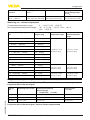
Adjustment
Adjustment range of the min./max. adjustment relating to the nominal measuring range:
ƲƲ Percentage value
-10 … 110 %
ƲƲ Pressure value
-20 … 120 %
Adjustment range of the zero/span adjustment relating to the nominal measuring range:
ƲƲ zero
-20 … +95 %
ƲƲ Difference between zero and span
max. 120 % of the nominal range
ƲƲ span
Recommended max. turn down
-120 … +120 %3)
20 : 1 (no limitation)
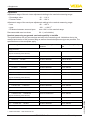
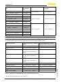
Nominal measuring ranges and overload capability in bar/kPa
The specifications are only an overview and refer to the measuring cell. Limitations due to the
material and version of the process fitting as well as the selected pressure type are possible. The
specifications on the nameplate apply.
Nominal range
Overload capacity, max.
pressure
Overload capacity, min. pressure
0 … +0.025 bar/0 … +2.5 kPa
+5 bar/+500 kPa
-0.05 bar/-5 kPa
0 … +0.1 bar/0 … +10 kPa
+15 bar/+1500 kPa
-0.2 bar/-20 kPa
0 … +0.4 bar/0 … +40 kPa
+30 bar/+3000 kPa
-0.8 bar/-80 kPa
0 … +1 bar/0 … +100 kPa
+35 bar/+3500 kPa
-1 bar/-100 kPa
0 … +2.5 bar/0 … +250 kPa
+50 bar/+5000 kPa
-1 bar/-100 kPa
0 … +10 bar/0 … +1000 kPa
+90 bar/+9000 kPa
-1 bar/-100 kPa
0 … +25 bar/0 … +2500 kPa
+130 bar/+13000 kPa
-1 bar/-100 kPa
0 … +60 bar/0 … +6000 kPa
+200 bar/+20000 kPa
-1 bar/-100 kPa
0 … +100 bar/0 … +10000 kPa
+200 bar/+20000 kPa
-1 bar/-100 kPa
-1 … 0 bar/-100 … 0 kPa
+35 bar/+3500 kPa
-1 bar/-100 kPa
-1 … +1.5 bar/-100 … +150 kPa
+40 bar/+4000 kPa
-1 bar/-100 kPa
-1 … +10 bar/-100 … +1000 kPa
+90 bar/+9000 kPa
-1 bar/-100 kPa
-1 … +25 bar/-100 … +2500 kPa
+130 bar/+13000 kPa
-1 bar/-100 kPa
-1 … +60 bar/-100 … +6000 kPa
+200 bar/+20000 kPa
-1 bar/-100 kPa
-1 … +100 bar/-100 … +10000 kPa
+200 bar/+20000 kPa
-1 bar/-100 kPa
-0.05 … +0.05 bar/-5 … +5 kPa
+15 bar/+1500 kPa
-0.2 bar/-20 kPa
-0.2 … +0.2 bar/-20 … +20 kPa
+20 bar/+2000 kPa
-0.4 bar/-40 kPa
-0.5 … +0.5 bar/-50 … +50 kPa
+35 bar/+3500 kPa
-1 bar/-100 kPa
Gauge pressure
(only for measuring cell ø 28 mm)
(only for measuring cell ø 28 mm)
(only for measuring cell ø 28 mm)
3)
Values less than -1 bar cannot be set.
44
VEGABAR 82 • Slave sensor for electronic differential pressure
45050-EN-131011
Absolute pressure
9 Supplement
Nominal range
Overload capacity, max.
pressure
Overload capacity, min. pressure
0 … 0.1 bar/0 … 10 kPa
15 bar/1500 kPa
0.8 bar abs.
0 … 1 bar/0 … 100 kPa
35 bar/3500 kPa
0 bar abs.
0 … 2.5 bar/0 … 250 kPa
50 bar/5000 kPa
0 bar abs.
0 … 10 bar/0 … 1000 kPa
90 bar/9000 kPa
0 bar abs.
0 … 25 bar/0 … 2500 kPa
130 bar/13000 kPa
0 bar abs.
0 … 60 bar/0 … 6000 kPa
200 bar/20000 kPa
0 bar abs.
0 … +100 bar/0 … +10000 kPa
200 bar/20000 kPa
0 bar abs.
(only for measuring cell ø 28 mm)
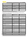
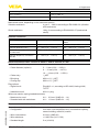
Nominal measuring ranges and overload capacity in psi
The specifications are only an overview and refer to the measuring cell. Limitations due to the
material and version of the process fitting as well as the selected pressure type are possible. The
specifications on the nameplate apply.
Nominal range
Overload capacity, max.
pressure
Overload capacity, min. pressure
0 … +0.4 psig
+75 psig
-0.725 psig
0 … +1.5 psig
+225 psig
-2.901 psig
0 … +5 psig
+435 psig
-11.60 psig
0 … +15 psig
+510 psig
-14.51 psig
0 … +30 psig
+725 psig
-14.51 psig
0 … +150 psig
+1300 psig
-14.51 psig
0 … +300 psig
+1900 psig
-14.51 psig
0 … +900 psig
+2900 psig
-14.51 psig
0 … +1500 psig
+2900 psig
-14.51 psig
-14.5 … 0 psig
+510 psig
-14.51 psig
-14.5 … +20 psig
+580 psig
-14.51 psig
-14.5 … +150 psig
+1300 psig
-14.51 psig
-14.5 … +300 psig
+1900 psig
-14.51 psig
-14.5 … +900 psig
+2900 psig
-14.51 psig
-14.5 … +1500 psig
+2900 psig
-14.51 psig
-0.7 … +0.7 psig
+225 psig
-2.901 psig
-3 … +3 psig
+290 psi
-5.800 psig
-7 … +7 psig
+510 psig
-14.51 psig
225 psig
0 psi
Gauge pressure
(only for measuring cell ø 28 mm)
(only for measuring cell ø 28 mm)
45050-EN-131011
(only for measuring cell ø 28 mm)
Absolute pressure
0 … 1.5 psi
VEGABAR 82 • Slave sensor for electronic differential pressure
45
9 Supplement
Nominal range
Overload capacity, max.
pressure
Overload capacity, min. pressure
0 … 5 psi
435 psi
0 psi
0 … 15 psi
510 psi
0 psi
0 … 30 psi
725 psi
0 psi
0 … 150 psi
1300 psi
0 psi
0 … 300 psi
1900 psi
0 psi
0 … 900 psi
2900 psi
0 psi
0 … +1450 psig
2900 psig
0 psi
(only for measuring cell ø 28 mm)
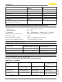
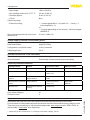
Reference conditions and actuating variables (according to DIN EN 60770-1)
Reference conditions according to DIN EN 61298-1
ƲƲ Temperature
+15 … +25 °C (+59 … +77 °F)
ƲƲ Air pressure
860 … 1060 mbar/86 … 106 kPa (12.5 … 15.4 psig)
ƲƲ Relative humidity
45 … 75 %
Determination of characteristics
Limit point adjustment according to IEC 61298-2
Characterstic curve
Linear
Reference installation position
upright, diaphragm points downward
Influence of the installation position
< 0.2 mbar/20 Pa (0.003 psig)
Deviation (according to IEC 60770)
Specifications refer to the set span. Turn down (TD) is the ratio: nominal measuring range/set span.
Accuracy class
Non-linearity, hysteresis and re- Non-linearity, hysteresis and repeatability with TD 1 : 1 up to 5 : 1 peatability with 5 : 1
0.05 %
< 0.05 %
< 0.01 % x TD
0.1 %
< 0.1 %
< 0.02 % x TD
0.2 %
< 0.2 %
< 0.04 % x TD
Influence of the product or ambient temperature
Thermal change zero signal and output span
Turn down (TD) is the relation nominal measuring range/adjusted span.
Measuring cell - Standard
Medium or ambient tem- Accuracy class 0.05 %,
perature T
0.1 %
Accuracy class 0.2 %
Accuracy class 0.2 %
with measuring range
0.1 barabs
0 … 40 °C
(+32 … +104 °F)
< {0.0075 %/K x (T 20 °C)} x {0.5+0.5 x TD}
< {0.005 %/K x (T - 20 °C)} < {0.015 %/K x (T - 20 °C)}
x {0.5+0.5 x TD}
x {0.5+0.5 x TD}
40 … 100 °C
(+104 … +212 °F)
< {0.15 % } x {0.5+0.5 x
TD}
< {0.005 %/K x (T - 20 °C)}
< {0.3 % } x {0.5+0.5 x TD}
x {0.5+0.5 x TD}
46
VEGABAR 82 • Slave sensor for electronic differential pressure
45050-EN-131011
-40 … 0 °C (-40 … +32 °F) < {0.15 % + 0.015 %/K x (- < {0.1 % + 0.03 %/K x (-T)} < {0.30 % + 0.03 %/K x (T)} x {0.5+0.5 x TD}
x {0.5+0.5 x TD}
T)} x {0.5+0.5 x TD}
9 Supplement
Medium or ambient tem- Accuracy class 0.05 %,
perature T
0.1 %
100 … 130 °C
(+212 … +266 °F)
Accuracy class 0.2 %
Accuracy class 0.2 %
with measuring range
0.1 barabs
< {0.15 % + 0.005 %/K x (T < {0.40 % + 0.01 %/K x (T - < {0.30 % + 0.01 %/K x (T - 100 °C)} x {0.5+0.5 x TD} 100 °C)} x {0.5+0.5 x TD} 100 °C)} x {0.5+0.5 x TD}
Measuring cell - climate-compensated
Compensated temperature range
Non-compensated temperature range
0 … +100 °C (+32 … +212 °F)
-40 … 0 °C (-40 … +32 °F), -100 … 130 °C
(212 … +276 °F)
Nominal measuring range in bar/
kPa
Nominal measuring
range in psig
0 … 10 bar/0 … 1000 kPa
0 … 150 psig
0 … 25 bar/0 … 2500 kPa
0 … 350 psig
0 … 60 bar/0 … 6000 kPa
0 … 900 psig
0 … 100 bar/0 … 10000 kPa
0 … 1450 psig
-1 … 0 bar/-100 … 0 kPa
-15 … 0 psig
-1 … 1.5 bar/-100 … 150 kPa
-15 … 25 psig
-1 … 10 bar/-100 … 1000 kPa
-15 … 150 psig
-1 … 25 bar/-100 … 2500 kPa
-15 … 350 psig
-1 … 60 bar/-100 … 6000 kPa
-15 … 900 psig
-1 … 100 bar/-100 … 10000 kPa
-15 … 1450 psig
0 … 1 bar/0 … 100 kPa
0 … 15 psig
0 … 2.5 bar/0 … 250 kPa
0 … 35 psig
-0.5 … 0.5 bar/-50 … 50 kPa
-7 … 7 psig
-0.2 … 0.2 bar/-20 … 20 kPa
-3 … 3 psig
0 … 0.4 bar/0 … 40 kPa
0 … 6 psig
In the compensated
temperature range
In the non-compensated temperature
range
< {0.05 % + 0.1 x
(0.5+0.5 x TD)}
< {0.1 % + 0.15 x
(0.5+0.5 x TD)}
< {0.1 % + 0.2 x
(0.5+0.5 x TD)}
< {0.1 % + 0.3 x
(0.5+0.5 x TD)}
< {0.15 % + 0.4 x
(0.5+0.5 x TD)}
< {0.15 % + 0.6 x
(0.5+0.5 x TD)}
Long-term stability (according to DIN 16086 and IEC 60770-1)
Specifications refer to the set span. Turn down (TD) is the ratio: nominal measuring range/set span.
45050-EN-131011
Long-term drift of the zero signal
Time period
Measuring cell ø 28 mm
Measuring cell ø 28 mm
Measuring cell
ø 17.5 mm
One year
< 0.05 % x TD
< 0.1 % x TD
< 0.1 % x TD
Five years
< 0.1 % x TD
< 0.2 % x TD
< 0.2 % x TD
Ten years
< 0.2 % x TD
< 0.4 % x TD
< 0.4 % x TD
Measuring range
0 … +0.025 bar/0 … +2.5 kPa
Long-term drift of the zero signal - Version climate-compensated
VEGABAR 82 • Slave sensor for electronic differential pressure
47
9 Supplement
Nominal measuring range in bar/ Nominal measkPa
uring range in
psig
0 … 0.4 bar/0 … 40 kPa
0 … 6 psig
-0.2 … 0.2 bar/-20 … 20 kPa
-3 … 3 psig
0 … 1 bar/0 … 100 kPa
0 … 15 psig
0 … 2.5 bar/0 … 250 kPa
0 … 35 psig
-1 … 0 bar/-100 … 0 kPa
-15 … 0 psig
-1 … 1.5 bar/-100 … 150 kPa
-15 … 25 psig
-0.5 … 0.5 bar/-50 … 50 kPa
-7 … 7 psig
0 … 10 bar/0 … 1000 kPa
0 … 150 psig
0 … 25 bar/0 … 2500 kPa
0 … 350 psig
0 … 60 bar/0 … 6000 kPa
0 … 900 psig
0 … 100 bar/0 … 6000 kPa
0 … 1450 psig
-1 … 10 bar/-100 … 1000 kPa
-15 … 150 psig
-1 … 25 bar/-100 … 2500 kPa
-15 … 350 psig
-1 … 60 bar/-100 … 6000 kPa
-15 … 900 psig
Measuring cell ø 28 mm
Measuring cell
ø 17.5 mm
< (1 % x TD)/year
< (1.5 % x TD)/year
< (0.25 % x TD)/year
< (0.375 % x TD)/year
< (0.1 % x TD)/year
< (0.15 % x TD)/year
Process conditions
Product temperature depending on the measuring cell seal4)
The specifications are an overview. The specification on the type plate are valid.
Product temperature - standard
version
Product temperature - version
with extended temperature range
FKM (VP2/A)
-20 … +130 °C (-4 … +266 °F)
-20 … +150 °C (-4 … +302 °F)
FKM (A+P 70.16)
-40 … +130 °C (-40 … +266 °F)
-
FKM (ET 7067)
-20 … +130 °C (-4 … +266 °F)
-
EPDM (A+P 75.5/KW75F)
-40 … +130 °C (-40 … +266 °F)
-40 … +150 °C (-40 … +302 °F)
EPDM (ET 7056)
-40 … +130 °C (-40 … +266 °F)
-
FFKM (Kalrez 6375)
-20 … +130 °C (-4 … +266 °F)
-20 … +150 °C (-4 … +302 °F)
FFKM (Perlast G75S)
-15 … +130 °C (-4 … +266 °F)
-15 … +150 °C (5 … +302 °F)
FFKM (Perlast G75B)
-15 … +130 °C (-4 … +266 °F)
-15 … +150 °C (5 … +302 °F)
FFKM (Chemraz 535)
-30 … +130 °C (-22 … +266 °F)
-
FEPM (Fluoraz SD890)
-5 … +130 °C (-22 … +266 °F)
-
1 h: 140 °C/284 °F cleaning temperature
1 h: 140 °C/284 °F cleaning temperature
1 h: 140 °C/284 °F cleaning temperature
Product temperature depending on the ambient temperature
4)
With process fitting PVDF, max. 100 °C (212 °F).
48
VEGABAR 82 • Slave sensor for electronic differential pressure
45050-EN-131011
Measuring cell seal
9 Supplement
Ambient temperature
Product temperature
+50 °C (+122 °F)
+150 °C (+302 °F)
+80 °C (+176 °F)
+100 °C (+212 °F)
Mechanical stress, depending on the instrument version
Vibration resistance
Shock resistance
4 g at 5 … 200 Hz according to EN 60068-2-6 (vibration
with resonance)
100 g, 6 ms according to EN 60068-2-27 (mechanical
shock)
Ambient conditions
Version
Ambient temperature
Storage and transport temperature
Standard version
-40 … +80 °C (-40 … +176 °F)
-60 … +80 °C (-76 … +176 °F)
Version IP 66/IP 68 (1 bar)
-20 … +80 °C (-4 … +176 °F)
-20 … +80 °C (-4 … +176 °F)
Version IP 68 (25 bar) with connection cable PUR
-20 … +80 °C (-4 … +176 °F)
-20 … +80 °C (-4 … +176 °F)
Version IP 68 (25 bar), connection
cable PE
-20 … +60 °C (-4 … +140 °F)
-20 … +60 °C (-4 … +140 °F)
Electromechanical data - version IP 66/IP 67 and IP 66/IP 68; 0.2 bar
Options of the cable entry
ƲƲ Cable diameter (options)
ƲƲ Cable entry
ƲƲ Blind plug
ƲƲ Closing cap
Plug options
ƲƲ Signal circuit
ƲƲ Indication circuit
5 … 9 mm (0.20 … 0.35 in)
6 … 12 mm (0.24 … 0.47 in)
10 … 14 mm (0.39 … 0.55 in)
½ NPT
M20 x 1.5; ½ NPT
M20 x 1.5; ½ NPT
Plug M12 x 1, according to ISO 4400, Harting HAN,
7/8" FF
M12 x 1 plug
Wire cross-section (spring-loaded terminals)
ƲƲ Massive wire, cord
ƲƲ Stranded wire with end sleeve
0.2 … 2.5 mm² (AWG 24 … 14)
0.2 … 1.5 mm² (AWG 24 … 16)
45050-EN-131011
Electromechanical data - version IP 68 (25 bar)
Connection cable between IP 68 instrument and external housing
ƲƲ Configuration
ƲƲ Wire cross-section
ƲƲ Wire resistance
ƲƲ Standard length
four wires, one suspension wire, one breather capillary,
screen braiding, metal foil, mantle
0.5 mm² (AWG 20)
< 0.036 Ω/m (0.011 Ω/ft)
5 m (16.40 ft)
VEGABAR 82 • Slave sensor for electronic differential pressure
49
9 Supplement
ƲƲ Max. length
180 m (590.5 ft)
ƲƲ Diameter approx.
8 mm (0.315 in)
ƲƲ Min. bending radius at 25 °C/77 °F
ƲƲ Colour
25 mm (0.985 in)
Blue
Cable entry/plug5)
ƲƲ External housing
–– 1 x cable gland M20 x 1.5 (cable: ø 5 … 9 mm), 1 x
blind plug M20 x 1.5
or:
Spring-loaded terminals for wire crosssection up to
–– 1␣x plug (depending on the version), 1␣x blind stopper
M20␣x␣1.5
2.5 mm² (AWG 14)
Voltage supply, interface to the master sensor
Voltage supply
Through the master sensor
Data transmission
digital (I²C-Bus)
Cable length max.
25 m
Configuration, connection cable
4-wire, screened
Potential connections in the instrument
Electronics
Not non-floating
Ground terminal
Galvanically connected with the process fitting
Electrical protective measures
Housing material
Version
IP-protection class
NEMA protection
Plastic
Single chamber
IP 66/IP 67
NEMA 4X/6P
Aluminium
Single chamber
IP 66/IP 68 (0.2 bar)
NEMA 4X/6P
Stainless steel, electropolished
Single chamber
IP 66/IP 68 (0.2 bar)
NEMA 4X/6P
Stainless steel, investment Single chamber
casting
IP 66/IP 68 (0.2 bar)
NEMA 4X/6P
Stainless steel
IP 68 (25 bar)
-
Overvoltage category
Protection class
IP 68 (1 bar)
Single chamber
IP 69K
IP 68 (1 bar)
Transmitter for external
housing
-
NEMA 4X
III
II
For that reason the associated approval documents of these instruments must be carefully noted.
They are part of the delivery or can be downloaded under www.vega.com and "VEGA Tools" as
well as under "Downloads" and "Approvals".
5)
Depending on the version M12 x 1, according to ISO 4400, Harting, 7/8" FF.
50
VEGABAR 82 • Slave sensor for electronic differential pressure
45050-EN-131011
Approvals
Instruments with approvals can have different technical data depending on the version.
9 Supplement
9.2Dimensions
The following dimensional drawings represent only an extract of the possible versions. Detailed
dimensional drawings can be downloaded at www.vega.com under "Downloads" and "Drawings".
Housing
~ 59 mm
(2.32")
ø 80 mm
(3.15")
~ 116 mm
(4.57")
ø 86 mm
(3.39")
M20x1,5/
½ NPT
M20x1,5
M20x1,5/
½ NPT
~ 69 mm
(2.72")
ø 79 mm
(3.11")
ø 80 mm
(3.15")
M20x1,5/
½ NPT
4
104 mm
(4.1")
117 mm
(4.61")
~ 59 mm
(2.3")
M20x1,5/
½ NPT
3
2
1
112 mm
(4.41")
112 mm
(4.41")
116 mm
(4.57")
~ 69 mm
(2.72")
ø 79 mm
(3.11")
M20x1,5/
½ NPT
5
Fig. 27: Housing versions in protection IP 66/IP 67 and IP 66/IP 68 (0.2 bar)
Plastic housing
Aluminium housing
Stainless steel housing, electropolished
Stainless steel housing, precision casting
Stainless steel housing, electropolished IP 69K
45050-EN-131011
1
2
3
4
5
VEGABAR 82 • Slave sensor for electronic differential pressure
51
9 Supplement
External housing with IP 68 version
80 mm
(3.15")
82 mm
(3.23")
41,6 mm
(1.64")
3
59 mm
(2.32")
108 mm
(4.25")
1
110 mm x 90 mm
(4.33" x 3.54")
41,6 mm
(1.64")
~ 66 mm
(2.60")
2
51 mm
(2.01")
4
110 mm x 90 mm
(4.33" x 3.54")
5
Fig. 28: IP 68 version with external housing - plastic version
1
2
3
4
5
Lateral cable outlet
Axial cable outlet
Plastic version
Stainless steel version
Seal 2 mm (0.079 in) - only with 3A approval
45050-EN-131011
52
VEGABAR 82 • Slave sensor for electronic differential pressure
9 Supplement
DD
17 mm
(0.67")
85 mm
(3.35")
G¼
DL
25 mm
(0.98")
M20x1,5
5 mm
(0.20")
¼ NPT
ø 17,5 mm
(0.69")
75 mm
(2.95")
DQ
15 mm
(0.59")
75 mm
(2.95")
73 mm
(2.87")
23 mm
(0.91")
ø 6 mm
(0.24")
½ NPT
25 mm
(0.98")
3 mm
(0.12")
ø 3 mm
(0.12")
G¼
ø 17,5 mm
(0.69")
DI
DU
G½
G½
20 mm
(0.79")
2 mm
(0.08")
ø 6 mm
(0.24")
17 mm
(0.67")
70 mm
(2.76")
23 mm
(0.91")
ø 3 mm
(0.12")
G½
3 mm
(0.12")
3 mm
(0.12")
SW 27 mm
(1.06")
G½
20 mm
(0.79")
73 mm
(2.87")
VEGABAR 82, threaded fitting not front-flush
ø 3 mm
(0.12")
C2
ø 6 mm
(0.24")
45050-EN-131011
Fig. 29: VEGABAR 82, threaded fitting not front-flush
DU G½ manometer connection (EN 837)
DI G½ A inside G¼ (ISO 228-1)
DQ G½ A inside G¼ A PVDF (ISO 228-1)
DD G½ manometer connection (EN 837) volume-reduced
DL ½ NPT
C2 M20 x 1.5 manometer connection (EN 837)
VEGABAR 82 • Slave sensor for electronic differential pressure
53
9 Supplement
VEGABAR 82, threaded fitting front-flush
C3
44 mm
(1.73")
G¾
SW 41 mm
(1.61")
G1
21 mm
(0.83")
ø 24 mm
(0.95")
C1
C5
SW 55 mm
(2.17")
ø 60 mm
(2.36")
50 mm
(1.97")
55 mm
(2.17")
G1 ½
DV
DA
ø 30 mm
(1.18")
ø 40 mm
(1.58")
SW 46 mm
(1.81")
22 mm
(0.87")
ø 55 mm
(2.17")
25 mm
(0.87")
G1 ½
50 mm
(1.97")
22 mm
(0.87")
44 mm
(1.73")
ø 18 mm
(0.71")
ø 27 mm
(1.06")
SW 46 mm
(1.81")
SW 36 mm
(1.42")
22 mm
(0.87")
21 mm
(0.83")
45 mm
(1.77")
SW 27 mm
(1.06")
G½
1 ½ NPT
ø 55 mm
(2.17")
C9
Fig. 30: VEGABAR 82, threaded fitting front-flush
C3
C1
C5
DA
DV
C9
G½ (ISO 228-1)
G¾ (DIN 3852-E)
G1 A (ISO 228-1)
G1½ (DIN 3852-A)
G1½ A PVDF (DIN 3852-A-B)
1½ NPT (ASME B1.20.1)
For the version with temperature range up to 150 °C/302 °F, the measure of length increases by
28 mm (1.1 in).
45050-EN-131011
54
VEGABAR 82 • Slave sensor for electronic differential pressure
9 Supplement
VEGABAR 82, hygienic fitting
55 mm
(2.17")
ø 48 mm
(1.89")
60 mm
(2.36")
51 mm
(2.01")
SW 46 mm
(1.81")
ø 64 mm
(2.52 ")
ø 66 mm
(2.60")
ø 78 mm
(3.07")
AR
ø 105 mm
(4.13")
ø 84 mm
(3.31")
FR
AA
50 mm
(1.97")
51 mm
(2.01")
51 mm
(2.01")
ES
ø 78 mm (3.07")
ø 92 mm (3.62")
EZ/E1
ø 92 mm
(3.62")
E3
Fig. 31: VEGABAR 82, hygienic fitting
Clamp 2"
Clamp 2½
Hygienic fitting with compression nut F40
DRD
Tuchenhagen Varivent DN 32
Bolting DN 40 according to DIN 11851
Bolting DN 50 according to DIN 11851
Bolting DN 50 according to DIN 11864-1
45050-EN-131011
AR
AS
ES
AA
FR
EZ
E1
E3
VEGABAR 82 • Slave sensor for electronic differential pressure
55
9 Supplement
b
d2
f
50 mm
(1.97")
VEGABAR 82, flange connection
d4
k
D
mm
DN
PN
D
b
k
d2
d4
f
1 A8
40
40
150
18
110
4xø18
88
3
B2
50
40
165
20
125
4xø18
102
3
R5
80
40
200
24
160
8xø18
138
3
2 CA
2”
150 lbs
152,4
19,1
120,7
4xø19,1
91,9
3,2
3”
150 lbs
190,5
23,9
152,4
8xø19,1
127
3,2
DN
PN
D
b
k
d2
d4
40
40
5.91" 0.71" 4.33" 4xø 0.71" 3.46"
0.12"
0.12"
CB
inch
1 A8
f
B2
50
40
6.50" 0.79" 4.92" 4xø 0.71" 4.02"
B5
80
40
7.87" 0.95" 6.30" 8xø 0.71" 5.43"
0.12"
2 CA
2”
150 lbs
6"
0.75" 4.75" 4xø 0.75" 3.62"
0.13"
3”
150 lbs
7.5"
0.94"
0.13"
CB
6"
8xø 0.75"
5”
Fig. 32: VEGABAR 82, flange connection
1
2
Flange connection according to DIN 2501
Flange connection according to ANSI B16.5
45050-EN-131011
56
VEGABAR 82 • Slave sensor for electronic differential pressure
9 Supplement
VEGABAR 82, extension fitting
M 44 x 1,25
ø 27,4 mm
(1.08")
AL/AP
G1
104,8 mm
(4.13")
30 mm
(1.18")
ø 25 mm
(0.98")
52 mm
(2.05")
M30x1,5
SW 36 mm
(1.42")
SW 46 mm
(1.81")
21 mm
(0.83")
AF/AG
ø 24,7 mm
(0.97")
30...300 mm
(1.18...11.81")
40 mm
(1.58")
40 mm
(1.58")
F9
ø 29,3 mm
(1.15")
F1
ø 32...60 mm
(1.26...2.36")
F2
ø 48...90 mm
(1.89...3.54")
25...300 mm
(0.98...11.81")
29 mm
(1.14")
48 mm
(1.89")
SW 32 mm
(1.26")
45050-EN-131011
Fig. 33: VEGABAR 82, extension fitting
AL M30 x 1.5
AP M30 x 1.5 for headbox
AF/AG
M44 x 1.25
F9 G1 (ISO 228-1) suitable for PASVE
F1 Flange DN 50 with selectable extension
F2 Flange DN 80 with selectable extension
VEGABAR 82 • Slave sensor for electronic differential pressure
57
9 Supplement
9.3
Industrial property rights
VEGA product lines are global protected by industrial property rights. Further information see
www.vega.com.
Only in U.S.A.: Further information see patent label at the sensor housing.
VEGA Produktfamilien sind weltweit geschützt durch gewerbliche Schutzrechte.
Nähere Informationen unter www.vega.com.
Les lignes de produits VEGA sont globalement protégées par des droits de propriété intellectuelle. Pour plus d'informations, on pourra se référer au site www.vega.com.
VEGA lineas de productos están protegidas por los derechos en el campo de la propiedad industrial. Para mayor información revise la pagina web www.vega.com.
Линии продукции фирмы ВЕГА защищаются по всему миру правами на интеллектуальную
собственность. Дальнейшую информацию смотрите на сайте www.vega.com.
VEGA系列产品在全球享有知识产权保护。
进一步信息请参见网站<www.vega.com>。
9.4Trademark
All the brands as well as trade and company names used are property of their lawful proprietor/
originator.
45050-EN-131011
58
VEGABAR 82 • Slave sensor for electronic differential pressure
INDEX
INDEX
A
Adjustment
––Density 34, 35
––Differential pressure, flow 32, 33
––Interface 35
––Level 32
––Menu 29
––Unit 30
S
Seal concept 9
Service
––Hotline 39
Setup
––Extended adjustment 29
––Quick setup 26
C
Connecting
––Mechanically 13
Connection
––Steps 21
––Technology 21
D
Default values 36
E
Effective pressure transmitter
––Characteristics values 38
F
Fault rectification 39
G
Gas-tight leadthrough (Second Line of Defense)
15
M
Maintenance 39
Measurement setup
––Density measurement 19
––Differential pressure measurement 17
––Interface measurement 18
––Level measurement 17
P
Parameterization example 31
Position correction 30
Pressure compensation 14, 15, 16
45050-EN-131011
R
Repair 41
Reset
––Basic settings 36
––Delivery status 36
VEGABAR 82 • Slave sensor for electronic differential pressure
59
All statements concerning scope of delivery, application, practical use and operating conditions of the sensors and processing systems correspond to the information
available at the time of printing.
Subject to change without prior notice
© VEGA Grieshaber KG, Schiltach/Germany 2013
VEGA Grieshaber KG
Am Hohenstein 113
77761 Schiltach
Germany
Phone +49 7836 50-0
Fax +49 7836 50-201
E-mail: [email protected]
www.vega.com
45050-EN-131011
Printing date: