1
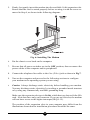
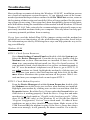
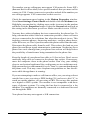
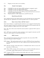
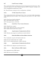
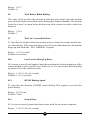
Table of Contents Do This First ................................................................................................................. 3 For Windows 3.1X Installation .............................................................................. 3 For Windows 95/98 Installation ............................................................................ 4 For Windows NT 4.0 Installation .......................................................................... 6 Installing the Modem ................................................................................................... 7 Jumper Settings ...................................................................................................... 7 Hardware Installation ............................................................................................ 8 Connecting Devices to the Modem ........................................................................ 10 Configuring Windows 95 ...................................................................................... 10 Configuring Windows 95 OEM Service Release 2 ............................................. 11 Configuring Windows 98 ...................................................................................... 11 Configuring Windows NT 4.00 ............................................................................ 12 Installing and Configuring Communications Software .......................................... 14 Using the Modems Voice Features ....................................................................... 14 Troubleshooting ............................................................................................................ 15 Appendix A - AT Commands and S-Registers ............................................................ 20 AT Commands ........................................................................................................ 21 S Registers .............................................................................................................. 28 Appendix B - Communications Regulations .............................................................. 31 Proprietary Notice and Disclaimer Unless otherwise noted, this document and the information herein disclosed are proprietary to ActionTec Electronics, Inc. Any person or entity to whom this document is furnished or who otherwise has possession thereof, by acceptance agrees that it will not be copied or reproduced in whole or in part, nor used in any manner except to meet the purposes for which it was delivered. The information in this document is subject to change without notice and should not be construed as a commitment by ActionTec. Although ActionTec will make every effort to inform users of substantive errors, ActionTec disclaims all liability for any loss or damage resulting from the use of this document or any hardware or software described herein, including without limitation contingent, special or incidental liability. Note: PC is a trademark of IBM Corporation. Windows 3.1, Windows 95, and Windows NT are trademarks of Microsoft, Inc. K56flex is a trademark of Lucent Technologies, Inc. and Rockwell International. 2 Do This First Please read the following tips carefully before attempting to install your new modem. For WINDOWS 3.1 INSTALLATION Because Windows 3.1 and 3.11 are not Plug-N-Play operating systems, it is suggested that you do not rely on the Plug-N-Play capabilities of your computer to automatically configure the modem. Instead, manually select the COM Port and IRQ setting by changing the jumpers. The jumper setting definitions can be found in the Installing The Modem section under the heading Jumper Settings. It is recommended that you disable an existing COM Port that you are not using, like COM 2, and set the modems jumpers for COM 2 -IRQ 3. This will avoid many of the pitfalls associated with installing a modem in Windows 3.1X. If you cannot disable an existing COM Port, then you must use COM Ports 3 or 4 and select an interrupt that does not cause a conflict with another device. If you do not know the available interrupts on your system, you will have to use trial-and-error to get the modem properly configured. To disable one of your computers existing COM Ports, you need to enter your System BIOS Setup routine (read your Computers User Manual for instructions on how to invoke the BIOS Setup). [If you have a seperate I/O card, use the cards jumbers to disable a COM Port]. Once inside the BIOS Setup, look for a section called Integrated Peripherals. Locate the entry for COM 2 or COM Port B and disable it. Save your settings before exiting. Install your modem into the computer and start Windows 3.1 or 3.11. Since you have manually selected the COM Port and IRQ settings of the modem using the jumpers, you will have to manually assign the IRQ and COM Port address in Windows 3.1X to the same settings as the modem. In Windows 3.1X Program Manager, double-click on Main and then on Control Panel. Double-click on Ports. Select the COM Port your modem is using by clicking once on the icon for that port. Click on Settings and then on Advanced. The COM Port is represented as an I/O address in hexadecimal format. Select 3F8 for COM 1, 2F8 for COM 2, 3E8 for COM 3, or 2E8 for COM 4 depending on which COM Port you selected your modem for. The IRQ setting will be selected by setting the IRQ box to the appropriate number. If you have set your modem to COM 2, then you would set the IRQ to 3. If you had chosen COM 3, then you would have set the IRQ jumper on the modem to an available IRQ setting, one that did not interfere with another device. You will need to set the Windows IRQ setting to this same number. After you have configured Windows 3.1X, close Windows and reboot your system. Install your communications software. 3 For WINDOWS 95/98 INSTALLATION If you are replacing an existing modem in your computer system with this modem, be sure to remove all other modem drivers. Go to: Start-SettingsControl Panel and double-click on the System icon. Select the Device Manager tab. Double-click on the Modems icon in the device tree to show the modems installed. Highlight each modem listed by clicking once on the icon next to the modem and then click the Remove button. It is also a good idea to physically remove your old modem from the system. Note: once you remove the old modem and its drivers from your system, you will need the old modem driver diskette if you wish to reinstall it at a later date. Figure 1: Win95 Modems Properties Panel If you are going to use the TAM (Telephone Answering Machine) or speakerphone functions of the modem, you need to install the Unimodem V components of Windows 95. If you have Windows 95 OEM Service Release 2 (Version 4.00.950 B or above) or Windows 98, you do not need to install this component as it is already built into the operating system. To find the Windows 95 Version on your system, select: Start-Settings-Control Panel. Double-click on the System icon and select the General tab. If the version of Windows 95 is 4.00.950 or 4.00.950A, go to: Start-Programs and select Windows Explorer. Go to the UNIMODEM directory of the CDROM (the UNIMODEM driver is sometimes supplied on a separate floppy) that came with your modem and right-click on UNIMODV.INF (or UNIMODV, whichever is displayed) then click on Install. Restart your computer to enable the drivers. 4 (Note: If you are using the default Play-N-Play jumper settings and not manually configuring the COM Port and IRQ jumpers, the following step may be skipped. Refer back to this area only if Plug-N-Play cannot successfully configure your modem.) The modem will need one IRQ (interrupt) and one COM Port to function. To check for any available interrupts in your system, go to Start-Settings-Control Panel. Double-click the System icon and select the Device Manager tab. Click the Properties button to view the System Resources. There are 16 (0-15) interrupts available in a system. Make a note of any interrupt not listed. If you do not have any free interrupts you may need to disable an existing device that you are not currently using, such as COM2 on your motherboard. This will free up I/O port 0x2F8 and IRQ 3. To disable COM2, boot your system and enter your BIOS setup. You can normally invoke the BIOS setup menu by pressing a key or a combination of keys at the first boot up screen. Some of the common keys are Del, F1, F2, Ctrl+Alt+S, Ctrl+Alt+Esc. If none of the mentioned key combinations work, please refer to your computer system manual for instructions on how to invoke the BIOS setup. (note: if your system uses a serate I/O Card, use the cards jumpers to disable a COM Port.) Once inside the BIOS setup, find the menu for integrated peripherals, locate the COM port settings, then disable COM2 or Comport B. If unsure, please consult your computer users manual. Be sure to Save the settings before exiting the BIOS Setup. The computer will then reboot. Set your modems jumpers to COM 2 - IRQ 3 (See Jumper Settings in the Installing the Modem section for jumper setting diagrams.). You will also need to disable the COM Port from the device manager. Go to Start-Settings-Control Panel double-click on the System icon, select the Device Manager tab. Double-click the Ports (COM & LPT) icon to expand the Ports tree and highlight Communication Port (COM2). Now click on the Properties button. Put a Check mark in Disable in this hardware profile (Windows 95 OEM SR2 only) or uncheck Original Configuration (current) (for Windows 95 or Windows 95a). Exit Windows 95 and restart your system. (Note: If COM 3 and or COM 4 are present and you have nothing installed on these ports, delete them first before deleting COM 2). (Note: If you are not familiar with changing the settings within your system BIOS setup, you should skip the following system preinstallation procedure and go to the Installing the Modem section. Refer back to this area only if you have a problem installing the modem.) 5 Go to your system BIOS Setup routine and find the Plug-N-Play settings. These settings can be found within the Advanced, PNP/PCI Configuration, or Plug and Play Configuration sections depending on the BIOS Manufacturer. Next, verify that one free IRQ has been set so that the ISA bus has access to it (some BIOS dont allow individual selection of interrupts to ISA, Plug-N-Play, or PCI). These settings can be called ICU, ICU/PCI, or PNP depending on your BIOS version and manufacturer. Do not set this interrupt to PCI only. Pay attention to the IRQ usage of the other peripherals in your system. Do not reassign an interrupt that is already in use by another device. Since each BIOS manufacturer has a different way of handling these configurations, you may have to use trial-and-error to get your modem properly configured. Be sure to Save the settings before exiting the BIOS Setup. You are now ready to install the modem. Proceed to the Installing the Modem section. For WINDOWS NT 4.0 INSTALLATION If you are replacing the current modem in your computer system with this new modem, be sure to remove all other modem drivers from your operating system. Go to: Start-Settings-Control Panel and double-click on the Modems icon. Highlight the modem you wish to remove and click the Remove button. Shutdown the computer, power-down, and physically remove the old modem from your system. Do not install your new modem at this time. Follow the procedures below to help insure a trouble-free installation. Note: once you remove the old modem and its drivers from your system, you will need the old modem driver diskette if you wish to reinstall it at a later date. It is seriously recommended that you DO NOT use the Plug-N-Play capabilities of the modem for a Windows NT installation. Instead, manually set the modems jumpers to COM 2 - IRQ 3 (see Jumper Settings in the Installing The Modem section). The use of a COM 2 - IRQ 3 setting will provide the least amount of system reconfiguration and aggravation for the installer. This setting will require that you disable your computers on-board COM2 Port. To disable COM2, boot your system and enter your BIOS setup. You can normally invoke the BIOS setup menu by pressing a key or a combination of keys at the first boot up screen. Some of the common keys are Del, F1, F2, Ctrl+Alt+S, Ctrl+Alt+Esc. If none of the mentioned key combinations work, please refer to your computer system manual for instructions on how to invoke the BIOS setup. Once inside the BIOS setup, find the menu for integrated peripherals, locate the COM port settings, then disable COM2 or Comport B. If unsure, please 6 consult your computers user manual. Be sure to Save the settings before exiting the BIOS Setup. The computer will then reboot. Set your modems jumpers to COM 2 - IRQ 3. (See Jumper Settings in the Installing the Modem section for jumper setting diagrams.) You are now ready to install the modem. Proceed to the next section. Installing The Modem JUMPER SETTINGS This modem has two sets of jumper blocks used for manual COM Port and IRQ (interrupt) selection. These are made available for users of non Plug-N-Play operating systems where the default jumper setting cannot be used. It also makes possible manual installation in a system where the installer wishes to use a specific COM Port and IRQ. Figure 2 shows the default jumper setting for JP1 and JP2 as shipped from the factory. This setting is for Plug-N-Play and will auto-configure in computers with operating systems that support this feature, like Windows 95 Figure 2: Jumpers Set To Plug-N-Play (default setting) The Jumper Block JP1 is used to select the desired COM Port for the modem. Figure 3: shows the selections for each COM Port. Figure 3: JP1 COM Port Options 7 Jumper Block JP2 is used to select the IRQ (interrupt request) settings for the modem. Figure 4: below details the possible selections. Figure 4: JP2 IRQ (interrupt request) Options HARDWARE INSTALLATION 1. Turn off the computer and all peripheral devices connected to it. 2. Unplug the computer power cord from the wall receptacle. 3. Remove the computers cover. Refer to your computer owners manual for instructions. 4. Remove the screw securing the expansion slot cover behind one of the computers available 16-bit ISA expansion slots. Lift the expansion slot cover out as shown below. Figure 5: Removing the Backplate 8 5. Firmly, but gently, insert the modem into the available 16-bit expansion slot. Ensure that the card is seated properly before securing it with the screw removed in Step 4, as shown in the following diagram: Fig. 6: Installing The Modem 6. Put the chassis cover back on the computer. 7. Be sure that all power switches are in the OFF position, then reconnect the power cables to the computer and its peripherals. 8. Connect the telephone line cable to the Line (Telco) jack as shown in Fig.7. 9. Turn on the computer and proceed to the following sections to configure your modem to the operating system you are using. Caution. Always discharge static electricity before handling your modem. You may discharge static electricity by touching a grounded metal structure or by using any commercially available grounding strap. Make sure the expansion slot type is 16-bit, which has two slots to fit the ISA card. 8-bit slots have only one connector. If you use an 8-bit slot, the modem will not have access to the higher interrupts (IRQ 9-15). The position of the expansion slots in your computer may differ from the illustrations shown but the installation procedure should be the same. 9 CONNECTING DEVICES TO THE MODEM Fig.7: Connecting Devices On the rear panel of your modem are input jacks to connect devices to the modem. As shown in the diagram, there are jacks for connection to a phone and to a phone line. The connector labeled Line (Telco) is meant to be connected to a standard analog phone line. To help reduce the load on your phone line, it is recommended that all other devices be disconnected from the phone line while the modem is in use. CONFIGURING WINDOWS 95 Step 1 Upon start-up, Windows 95 detects the modem and displays the New Hardware Found dialog box. Select Driver from disk provided by hardware manufacturer then Click OK. Step 2 Insert the diskette (or CD-ROM) containing the modems Windows 95 .INF files and click OK Step 3 If Windows asks for an installation disk, click OK and type A: (or CDROM drive letter) in the dialog box that appears and click OK again. Step 4 After the installer has copied the .INF files to the hard disk, a New Hardware Found dialog box should appear prompting for the Wave Device for Voice Modem. Click OK. (see the Do This First section for information on UNIMODEM.INF if this screen does not appear). 10 Step 5 Click OK to copy the Wave Device .INF file from the A:\ drive to the hard drive. Step 6 To determine what COM port and IRQ is assigned to the modem in Windows 95, click on the Modems icon in Control Panel and select the Diagnostic tab. Click on the COM Port icon and then on the More Info button to view the modem properties. CONFIGURING WINDOWS 95 OEM SR2 Step 1 Upon start-up, Windows 95 detects the modem and launches the Update Device Driver Wizard dialog box. Insert the diskette (or CD-ROM) containing the modems .INF files and click Next >. Step 2 After Windows 95 has found the updated drivers for your modem, click Finish. Step 3 If Windows asks for an installation disk, click OK and type A: (or the CD-ROM drive letter) in the dialog box that appears and click OK. Step 4 After the Wizard has copied the .INF files to the hard disk, it should detect Wave Device for Voice Modem and prompt for its driver. Click Next>. Step 5 Click Finish to copy the Wave Device .INF file from the A:\ drive (or CD-ROM) to the hard drive. Step 6 To determine what COM port and IRQ is assigned to the modem in Windows 95, click on the Modems icon in Control Panel and select the Diagnostics tab. Select your modem and then click on the More Info button to view the modem properties. Step 7 Remember this COM port number. When you install your Data/Fax software or internet browser program, you may need to set your softwares modem port location to this same number. CONFIGURING WINDOWS 98 Step 1 Turn on the computer and load Windows 98. Windows 98 will detect new hardware and start building the driver database. Step 2 An Add New Hardware Wizard should appear. Insert the installation 11 diskette or CD-ROM into the appropriate drive. Click Next>. Step 3 Windows will show a screen asking What do you want Windows to do?. Select: search for the best driver for your device. Click Next>. Step 4 A search screen will display options to do your search. Put a check on Floppy disk drives and CD-ROM drive. Click Next>. Step 5 Windows 98 will find the Fax/Modem driver on the floppy drive. If your modem came with a CD-ROM, Windows 98 will find the driver on the CD-ROM. Click Next>. Step 6 At the next screen, click Finish. Step 7 A new Add New Hardware Wizard should appear again prompting for wave device for voice modem. Click Next>. Step 8 Windows will show another What do you want Windows to do? screen. Select: search for the best driver for your device. Click Next>. Step 4 A search screen will display options to do your search. Check to see that a check still appears on Floppy disk drives and CD-ROM drive. Click Next>. Step 5 Windows 98 will find the wave driver on the floppy drive. If you have installation CD-ROM, Windows 98 will find the driver on the CD-ROM. Click Next>. Step 6 Windows 98 will finish the installation. Your modem is now ready to use. Install or reconfigure your communications program or Internet Browser for the new modem. Note: If you have installed your modem in Windows 95 and are upgrading your operating system to Windows 98, uninstall the modem and its drivers before attempting the upgrade. After you have finished and verified that your system is working properly, reinstall the modem into Windows 98 using the driver files provided in your modem package. CONFIGURING WINDOWS NT 4.00 This installation assumes that you have manually set the modems jumpers to a COM 2 - IRQ 3 setting as outlined in the Do This First section at the beginning of the manual. COM 2, IRQ 3 is the preferred installation setting for Windows NT. 12 Step 1 Reboot the computer and log in to Windows NT 4.00. Step 2 Go to: Start-Settings-Control Panel and double-click on the Modems icon. At the Modems Properties dialog box, click Add. Step 3 An Install New Modem window should appear. Allow Windows NT to detect your modem. Click on the Next> button. Step 4 If a modem is found, Windows NT will query it. In most cases Windows NT will detect the modem as a Standard Modem. Click on the Change button. Step 5 Insert the diskette (or CD-ROM) containing the modems .inf files and click the Have Disk button. When prompted for the path, type A:\ (or the CD-ROM Drive letter) and then click the OK button. Step 6 When prompted to select the manufacturer and model of the modem, click the OK button. At the next screen click the Next> button. Step 7 Click on the Modems icon in the Control Panel. Verify that Windows NT has correctly found the modem. Step 8 If you wish to use your modem to dial into a Windows NT Remote Access Server or wish to connect to the Internet, you will need to configure Dial-up Networking. Go to: Start-Settings-Control Panel and doubleclick the Network icon. Click on the Services folder and select Remote Access Service. If the Remote Access Service option is not listed (if present, go to Step 9), click on the Add button. Scroll-down the menu and select Remote Access Service. Click on the OK button. Windows NT may ask for its own disks or CD-ROM for some files. Insert as required. After you have installed Remote Access Service add the appropriate protocols as directed (i.e.. TCP/IP for Internet Access). Step 9 At the Remote Access Setup dialog box, click on Add . Select the RAS Device you wish to add and Click OK. Step 10 Click Continue to finish the Installation. Step 11 After Windows NT has completed the binding process, allow Windows NT to shut down and restart the computer. 13 Installing and Configuring Communications Software If your modem came with a communications software package, it is strongly recommended that you use this software for your modem. Its default installation parameters have been specially configured to work with this modem. The Users Guide for this program can be found inside the modem package. It can be supplied in either soft-bound copy or on CD-ROM (depending on the model you purchased). Some configurations are packaged without communications software. Check your packaging to see if communications software is included. If you wish to use another software package, please be sure that it supports this modem. Most Software Manufacturers have a listing of supported modems on their websites or BBSs. Check these sites to see if this model is supported. If you are unsure or your brand of software supports only a few modems, try selecting Hayes Compatible or Standard Modem. This may work in certain cases. Some software programs allow manual input of parameters. For the users of these programs, here is a listing of the Data/Fax/Voice Command Standards supported. Data: Fax: Voice: Init String: TIA/EIA-602 TIA/EIA-578 for Class 1 Fax TIA IS-101 support for TAD (Telephone Answering Device) and Full-Duplex Speakerphone. AT&F&C1&D2W2 TIA IS-101 Commands not supported: Caller ID VoiceView Note: some programs must be configured to communicate with the modem on the same COM port and or IRQ setting used by the modem. See the Installing the Modem section for instructions on how to determine your COM Port and IRQ settings in Windows 95. Using the Modems Voice Features This modem supports TIA IS-101 commands applicable to a Full Duplex Speakerphone and Telephone Answering Device. In order to take advantage of these features, you will need an external microphone and external speakers. A software application; such as the one supplied with the modem; which supports these functions is also required. If you wish to immediately take advantage of these features, install the enclosed Cheyenne BitWare Software and attach a microphone and pair of speakers to the modem. (see the CONNECTING DEVICES TO THE MODEM section) 14 Troubleshooting Most problems encountered during the Windows 95/98/NT installation process are a result of inadequate system resources. If you skipped some of the recommended preinstallation procedures outlined in the Do This First section, return to the beginning of that section and carefully follow all steps outlined for the operating system you are using. These steps have been thoughtfully chosen to help minimize difficulties during the installation of the modem in both Windows 95/98 and Windows NT 4.00. Take seriously the recommendation to physically remove any previously installed modems from your computer. This step alone can help prevent many potential problems from occurring. If you have used the default Plug-N-Play jumper settings and the modem has installed but is not functioning, try the troubleshooting procedure listed below. The information provided by following these steps can help point the way to fixing your difficulty. Windows 95/98 STEP 1: Check System Resources. Go to Start-Settings-Control Panel and double-click the System icon. Select the Device Manager tab. From the device tree, double-click the Modems icon to show what modems are installed. If there is no Modems icon, your modem did not install (see Does Not Install section). If your modem is listed, check that there is no yellow exclamation mark or red X over the modems telephone icon (if there is, go to STEP 2). If any other modems are listed, highlight the modem by clicking once on the telephone icon next to the listed modem and then click on the Remove button. Shutdown the system and turn off the power. Wait 5 seconds and turn your computer back on and repeat STEP 1. STEP 2: Check Modem Properties. From the Device Manager tab within System Properties, double-click the Modems icon in the device tree to show what modems are installed. Highlight your modem by clicking once on the icon and then click the Properties button. Read the Device Status under the General tab to see if the device is working properly. Check the Device Usage box and make sure there is no check mark on Disable in this hardware profile (Windows 95 OEM SR2 only) or (for Windows 95 or 95a) the box labeled Original Configuration, Current has a check mark . If either of these conditions are not as they should be, correct them. Make a note of the COM Port and IRQ the modem is using. If the Device Status box shows some error message, it will generally be about a conflict. Go to the Re- 15 sources tab and read the Conflicting Device List. If a conflict is present, uncheck the box Use automatic settings and select a configuration that does not cause conflicts. Manually change the IRQ settings if needed (see your Windows 95 on-line help file for a more detailed discussion on changing these settings). Click on the OK button. If there is no setting free of conflicts, go to the Does Not Install section. STEP 3: Modem Diagnostics. Go to Start-Settings-Control Panel and double-click the Modems icon. Your modem should be listed. If any other modem is listed, click once on each old modem and then click the Remove button. It is a good idea to shutdown Windows 95, turn off your computer, wait 5 seconds and turn the power back on (do not use the Shutdown and Restart option). Return to STEP 3: Modem Diagnostics and click on the Diagnostics tab. Highlight the modem by clicking once on the COM Port icon next to its listing. Now click on the More Info button. You should see the panel below. Figure 8: More Info Panel If you receive an error message or the panel is blank, go to the Does Not Install section. STEP 4: Does Not Install. The most likely reason for a non-installation in Windows 95/98 is a lack of IRQ resources. The modem needs one IRQ and one COM Port in order to function. Modern computer systems are usually equipped with soundcard, CD-ROM drive, Hard-drive, floppy drive, video card, two 16 COM Ports, one LPT port, keyboard, and a mouse. Each of these devices require at least one IRQ (interrupt) in order to function. Some models of sound card require three interrupts. It is little wonder that when it comes time to install a modem, there is nothing left. The addition of special purpose peripherals (SCSI, Network cards, etc.) makes matters worse. This section deals with the process of freeing IRQs and configuring the system P-N-P (Plug-N-Play) which requires that you know how to enter your computer systems BIOS Setup Routine (read your computers user manual for information on how to invoke and use the BIOS setup). Once inside the BIOS Setup, find the Plug-N-Play configuration. This can be found within the Advanced, PNP/PCI Configuration, or Plug and Play Configuration section depending on the BIOS Manufacturer. Next, from the information you noted in STEP 2: Modem Properties, find the interrupt selection for the IRQ your modem is using (some BIOS dont allow individual selection of interrupts to ISA, Plug-N-Play, or PCI). You want to set this to a Plug-N-Play setting. This can be called ICU/ PCI, ISA, or PNP depending on your BIOS version and manufacturer. Do not set this interrupt to PCI only or to Legacy ISA. Since each system manufacturer has a different way of handling this configuration, you may have to use trial-and-error to get your modem properly configured. If you do not have any free interrupts available, you will have to disable some unused function of your computer system. If you are using a PS/2 style mouse, you probably can spare one of your internal COM Ports. To disable a COM Port, find the BIOS Setup section for Integrated Peripherals. Locate the Serial Port settings and disable an unused port that has nothing connected to it (usually serial port 2). This should free one IRQ for your modem to use. You will also have to disable the COM Port in Windows 95 (see the Do This First Section). Special Situations: Under some situations, you will find that freeing an interrupt does not solve your installation difficulties. This could be due to another peripheral device stealing the interrupt you just provided. Certain full-featured sound cards require three IRQs to support all their functions. When one becomes available, they take it. This situation requires that you remove your sound card, free an interrupt, install the modem and verify its operation, and then reinstall the sound card. This procedure may also work for sound cards that have lost their sound after the modem has been installed or if the modem will not install in a system with a sound card. 17 Common Problems: No Dialtone Error Make sure you have connected the phone cable into the right connector on the back of the modem. See Figure 7: Connecting Devices. You may have too many devices connected to the phone line. Remove all other equipment. Your modem may not recognize overseas dialtone. Use ATX0 to have the modem ignore (not look for) the dialtone before dialing. Communications Software Does Not Work Some communications software packages need to be configured to the same COM Port and or IRQ as the modem. See the Installing the Modem section for information on how to determine your COM Port and IRQ number. Does the communications software support this modem? See the Installing and Configuring Communications Software section. If you are using a different software from the one supplied with the modem (some models of this modem may be shipped without communications software), try installing the supplied software and verify its functionality with the modem. Nothing Appears On The Screen When I Type in Terminal Mode Issue the command ATE1 to the modem to enable command echo. This will let you see what you type. The Modem Wont Answer the Phone (Cannot Detect Ring) Issue the command ATS0=1 to the modem to enable auto-answer mode. Entering the above command will cause the modem to answer on the first ring. After Upgrading to Windows 98, The Modem Wont Work Uninstall the modem and its drivers BEFORE upgrading to Windows 98. After you have finished the upgrade and verified that your system is working properly, reinstall the modem and its drivers. Cant Connect at 56K Note: Current FCC regulations limit your maximum connection rate to 53K bits / s. 18 The number you are calling may not support V.90 protocols. Some ISPs (Internet Service Providers) have special numbers that you must call to connect to V.90. Contact your service provider and ask if the number you are calling supports V.90 connections to their service. Check the maximum speed setting in the Modem Properties window. Go to Start-Settings-Control Panel and double-click the Modems icon. Highlight your modem by clicking once on the icon next to the modem and then click the Properties button. Select the General tab and look at the setting in the Maximum speed box. Make sure this is set to 115200. You may have other telephone devices connected to the phone line. To help your modem achieve the best connection possible, remove all extra devices connected to the telephone line when the modem is in use. This includes extension phones, answering machines, cordless phone bases, caller ID boxes, etc. Dont just disconnect the phone cable from the units. Disconnect the phone cable from the wall. This reduces the load on your phone line and keeps signal attenuation to a minimum. Not having loose phone line cords coming from your phone line sockets will help reduce the possibility of interference being transmitted to the phone line. Keep the length of your phone line cable to 10 feet or less. Dont use an unusually long cable to connect to the phone line socket. If necessary, move the computer closer to the phone socket. Dont lay your cabling close to an electrical appliance like a refrigerator or air conditioner unit. High current devices can transmit 60 cycle hum to your modem through the phone cord. This may cause frequent renegotiations or line disconnects while the appliance is running. If you are attempting to make a call from an office, are you using a direct outside line or are you using a PBX hookup? If you have to dial 9 to reach an outside number, you are using a PBX. Do not use this modem on a digital or PBX system. The modem is not compatible with these types of phones systems. Try using the line that is connected to a fax machine. Fax machines are normally connected to a dedicated line and not through the PBX. Your phone line may not support a 56K connection. 19 Appendix A: AT Command Set AT Commands AT commands are issued to the modem to control the modems operation and software configuration. AT commands can only be entered while the modem is in command mode. The format for entering AT commands is: TYPE: ATXn where X is the AT command, and n is the specific value for that command. PRESS: Enter Any command issued is acknowledged with a response in text format known as result codes. For multiple AT commands in the same command line, the commands are executed in the order received from the DTE. Should execution of a command result in an error, or a character not be recognized as a valid command, execution is terminated, the remainder of the command line is ignored, and the ERROR result code is issued. Otherwise, if all commands execute correctly, only the result code associated with the last command shall be issued; result codes for preceding commands are suppressed. In the following listing, commands and command values accepted by the modem are shown; any entries other than those shown cause the ERROR result code. AT Commands may be entered in upper or lower case letters but you should not mix upper case and lower case letters within the same command line. +++AT<CR> Escape sequence The escape sequence allows the modem to exit data mode and enter on-line command mode. While in on-line command mode, you may communicate directly to your modem using AT commands. Once you are finished, you may return to data mode using the ATO command. If you are in data mode and wish to enter command mode, you must type the escape character (the value stored in S2, typically +) three times followed by a valid AT Command and the carriage return character specified by S-Register S3 (typically <enter>). Using the default values of S2 and S3, the escape sequence would be like this: +++at<enter> S-Registers S-registers generally affect how the AT commands perform. Contents of the registers can be displayed or modified when the modem is in command mode. To display the value of an S-register: 20 TYPE: ATSn?<enter> where n is the register number. To modify the value of an S-register: TYPE: ATSn = r<enter> where n is the register number, and r is the new register value. Common AT Commands and S Registers The following are some common AT Commands. If you require a complete listing of the AT Command and S Register options, they are sometimes included as text files in the Installation Diskette or CD-ROM that came with your modem. A/ Repeat Last Command This command repeats the last command string entered. Do not precede this command with an AT prefix or conclude it by pressing Enter. A Answer Command This command instructs the modem to go off-hook and answer an incoming call. Bn Communication Standard Setting This command determines CCITT vs. Bell standard. B0: B1: B2: B3: Selects CCITT V.22 mode when the modem is at 1200 bits/s. Selects Bell 212A when the modem is at 1200 bits/s (default). Selects V.23 Orig: (75bps trans - 1200bps rec). Answr: (75bps rec - 1200 trans). Selects V.23 reverse channel ( opposite of B2). Cn Carrier Control C0: C1: Dn Transmit carrier always off. Normal transmit carrier switching. Dial This command instructs the modem to begin the dialing sequence. The dial string (n, the telephone number) is entered after the ATD command. En Echo Command 21 This command controls whether or not the characters entered from your computer keyboard are echoed back to your monitor while the modem is in command mode. E0: E1: Fn Disables echo to the computer. Enables echo to the computer (default). On-line Data Character Echo Command This command determines if the modem will echo data from the DTE. F0: F1: Hn On-line data character echo enabled (NOT SUPPORTED, ERROR). On-line character echo disabled. (default) Hook Control This command instructs the modem to go on-hook to disconnect a call, or offhook to make the phone line busy. H0: H1: In Modem goes on-hook (default). Modem goes off-hook. Request ID Information This command displays specific product information about the modem. I0: I1: I2: I3: I4: I5: I6 I7 I8 Ln Reports product code. Reports modem chip firmware version. Performs a ROM check and calculates and verifies the checksum displaying OK or ERROR. Reports chipset name. Reserved. Reserved. Country code. Reports board version number. Reports modem firmware features. Monitor Speaker Volume This command sets speaker volume to low, medium, or high. L0: L1: L2: L3: Selects lowest volume. Selects low volume. Selects medium volume (default). Selects high volume. 22 Mn Monitor Speaker Mode This command turns the speaker on or off. M0: M1: M2: M3: On O0: O1: O3: P The speaker is off. The speaker is on until the modem detects the carrier signal (default). The speaker is always on when modem is off-hook. The speaker is on until the carrier is detected, except while dialing. Return On-line to Data Mode Instructs the modem to exit on-line command mode and return to data mode (see AT Escape Sequence, +++). This command issues a retrain before returning to on-line data mode. This command issues a rate renegotiation before returning to on-line data mode. Select Pulse Dialing This command configures the modem for pulse (non-touch-tone) dialing. Dialed digits are pulsed until a T command or dial modifier is received. Tone dial is the default setting. Qn Result Code Control Result codes are informational messages sent from the modem and displayed on your monitor. Basic result codes are OK, CONNECT, RING, NO CARRIER, and ERROR. The ATQ command allows the user to turn result codes on or off. Q0: Q1: T Enables modem to send result codes to the computer (default). Disables modem from sending result codes to the computer. Select Tone Dialing This command instructs the modem to send DTMF tones while dialing. Dialed digits are tone dialed until a P command or dial modifier is received. This is the default setting. Vn DCE Response Format This command controls whether result codes (including call progress and negotiation progress messages) are displayed as words or their numeric equivalents. V0: Displays results as numbers. 23 V1: Wn W0: W1: W2: W3: W4: Zn Displays result codes as text (default). Result Code Option CONNECT result code reports DTE (modem to computer) speed. CONNECT result code reports DTE speed. CONNECT result code reports DCE (modem to modem) speed. CONNECT result code reports DTE speed and information on error correction and data compression. Reports protocol., data compression, and DTE data rate. Recall Stored Profile This command instructs the modem chip set to go on-hook and restore the profile specified by the n parameter. Z0 restores profile 0 and Z1 restores profile 1. &Cn Data Carrier Detect (DCD) Control Data Carrier Detect is a signal from the modem to your computer indicating that the carrier signal is being received from a remote modem. DCD normally turns off when the modem no longer detects the carrier signal. &C0: The state of the carrier from the remote modem is ignored. DCD circuit is always on. &C1: DCD turns on when the remote modems carrier signal is detected, and off when the carrier signal is not detected (default). &Dn DTR Control This command interprets how the modem responds to the state of the DTR signal and changes to the DTR signal. &D0: Ignore. The modem ignores the true status of DTR and treats it as always on. This should only be used if your computer does not provide DTR to the modem. &D1: Modem switches from data mode to command mode when an on-to-off transition of DTR occurs. &D2: When DTR switches off, the modem goes on-hook and disables auto-answer mode; when DTR switches on, auto-answer is enabled. &D3: Turning off DTR re-initializes the modem and resets values except for the UART registers. 24 &F Load Factory Settings This command loads the configuration stored and programmed at the factory. This operation replaces all of the command options and the S-register settings in the active configuration with factory values. &F: Recall factory setting as active configuration. (default) &Gn V.22bis Guard Tone Control This command determines which guard tone, if any, to transmit while transmitting in the high band (answer mode). This command is only used in V.22 and V.22bis mode. &G0: Guard tone disabled (default). &G1: Sets guard tone to 550 Hz. &G2: Sets guard tone to 1800 Hz. &Kn Serial Port Flow Control Selection &K0: Disable flow control. &K3: Enable RTS/CTS flow control (default). &K4: Enable XON/XOFF flow control. &Mn Asynchronous Communications Mode &M0: Modem only supports asynchronous mode.(default) &Pn Pulse Dial Make-to-Break Ratio Selection This Command sets pulse-dial make-break ratio. &P0 39%/61% make/break ratio, 10PPS &PI 33%/67% make/break ratio, 10PPS (default) &Qn Asynchronous Communications Mode &Q0: Modem only supports asynchronous mode. &Sn Data Set Ready (DSR) Option This command selects DSR action. &S0: DSR always ON (default). 25 &S1: DSR comes on when establishing a connection and when carrier is lost. &Vn View Active Configuration and Stored Profile This command is used to display the active profiles. &V0: View stored profile 0. &V1: View stored profile 1. &V3: View relay and general-purpose input-output status. &Wn Store Current Configuration This command stores certain command options and S-register values into the modems nonvolatile memory. The ATZ command or a power-up reset of the modem restores this profile. &W0: Store in user profile 0. &W1: Store in user profile 1. &Yn Select Stored Profile On Power-UP This command selects user profiles on power-up: &Y0: Recall stored profile 0 on power-up &Y1: Recall stored profile 1 on power-up. &Zn=x Store Telephone Number This command is used to store up to four dialing strings in the modems nonvolatile memory for later dialing. The format for the command is &Zn = stored number where n is the location 0-3 to which the number should be written. The dial string may contain up to 30 digits. The ATDS = n command dials using the string stored in location n. %En Auto-Retrain Control This command enables-disables auto-retrain: %E0: Disables auto-retrain. %E1: Enables auto-retrain (default).. %Gn Rate Renegotiation This Command enables-disables rate-renegotiation. 26 %G0: Disabled. %G1: Enabled. -Cn Data Calling Tone Data Calling Tone is a tone of certain frequency and cadence as specified in V.25 which allows remote Data/FAX/Voice discrimination. The frequency is 1300 Hz with a cadence of .5 s on and 2 s off. -CO: Disabled. -C1: Enabled. (default) -C2: Enable V.8 and 1300 Hz calling tone. +MS=m Modulation Selections. This Command selects modulation standards and transmit-receive speeds. To display the current setting, type AT+MS?. The proper command syntax is: AT+MS=<carrier>,<automode>,<min rate>,<max rate> <carrier> This parameter specifies the type of modulation standard used. The list below shows approved codes: V21 V22 V22B V23C V32 V32B V34 V34S V34B V90 V.21 (300 bps) V.22 (1200 bps) V.22 bis (1200 and 2400 bps) V.23, constant carrier (1200 bps forward and 300 bps reverse) V.32 (4800 and 9600 bps) V.32 bis (7200, 9600, 12200, and 14400) V.34 asymmetrical (2400, 4800, 7200, 9600, 12200, 14400, 16800, 19200, 21600, 24000, 26400, 28800, 31200, and 33600 bps) V.34 symmetrical only (2400, 4800,7200, 9600, 12200, 14400, 16800, 19200, 21600, 24000, 26400, 28800, 31200, and 33600 bps) V.34 extended asymmetrical (2400, 4800, 7200, 9600, 12200, 14400, 16800, 19200, 21600, 24000, 26400, 28800, 31200, and 33600 bps) V.90 asymmetrical [transmit speeds (4800, 7200, 9600, 12000, 14400, 16800, 19200, 21600, 24000, 26400, 28800, and 31200 bps)]; [receive speeds (33333, 37333, 41333, 42667, 44000, 45333, 46667, 48000, 49333, 50667, 52000, and 53333 bps)] <automode> This parameter allows the modem to negotiate modulation speeds automatically. 0= disabled (modem will not negotiate speeds automatically) 1= enabled (automatic negotiation allowed) 27 <min rate> This entry specifies the lowest data transfer rate which the modem may establish a connection. <max rate> This parameter specifies the highest speed at which the modem may establish a connection. S0 Number of Rings to Auto-answer The modem automatically goes off-hook and initiates a data mode-answer mode handshake after detecting the specified number of rings. A value of zero ( 0 ) disables auto-answer mode. Entering a value from 1 to 255 enables auto-answer mode. Range: 0-255 rings Default: 0 S2 Escape Character The value of S2 specifies an ASCII value for the character used to enter command mode. A value over 127 disables the escape sequence. Range: 0-127 Default: 43 S3 Carriage Return Character S3 specifies the AT command string terminator and modem response code terminator. The default is <CR> or carriage return (ASCII 13). Range: 0-127 Default: 13 S4 Line Feed Character The value of S2 specifies the line feed character. Range: 0-127 Default: 10 S5 Backspace Character S5 specifies the backspace character that is used to delete the last entered character. The default value is <backspace> (ASCII 8). 28 Range: 0-127 Default: 8 S6 Wait Before Blind Dialing The value of S6 specifies the amount of time that must elapse after the modem goes off-hook before the modem starts dialing the telephone number. The modem waits for at least 2 seconds before dialing even if the register is set for a value less than two. Range: 2-255 Default: 2 S7 Wait for Carrier/Dial Tone S7 specifies the length of time the modem waits to detect the remote modem carrier after dialing. If the remote modem is not detected within that time, the modem hangs up and sends the NO CARRIER response. Range: 1-255 seconds Default: 60 seconds S10 Lost Carrier Hang Up Delay S10 is used to specify the length of time the modem waits before hanging up if the remote modem carrier signal is lost. When set to 255, the modem does not hang up when it loses the remote modem. Range: 1-255 (1/10 of a second) Default: 14 (1.4 seconds) S11 DTMF Dialing Speed S11 specifies the duration of DTMF (tone) dialing. This register is not used for pulse dialing. Range: 50-255 ms. Default: 70 ms. S12 Guard Time S12 is used to specify guard and detect times used for the escape sequence. Range: 1-255 (1/50 of a second) 29 Default: 50 (1 second) S25 Detect DTR Change S25 defines the minimum amount of time that DTR has to remain off before the modem performs the function specified by the &Dn command. A change in DTR that persists for a shorter time than that specified will be ignored by the modem. Range: 1-255 1/100 of a second Default: 5 (1/20 of a second) S30 Disconnect Inactivity Timer This register sets the length of time that the modem stays on-line/off-hook before disconnecting when no data is being sent or received. Range: 1-255 minutes Default: 1 minute S33 Sleep Mode Timer S33 determines when the modem enters sleep or power-down mode. When enabled ( any value other than zero), the controller enters sleep mode whenever the modem has been inactive for a user-programmed time delay. The modem exits sleep mode whenever the host computer reads or writes to the modem or when a ring signal is detected. Range: 0-90 seconds Default: 0 (disabled) S37 Maximum Line Speed Attempted This register sets the maximum line speed allowed. S37 provides the same information as the AT+MS=m command. Using the +ms=m parameter automatically changes the value of S37. For example, setting AT+MS=0 sets S37 to 0 (zero). Using the AT+MS=m command to change the value of S37 provides greater flexibility than changing the S register directly. See the AT+MS=m command for more information. 30 Appendix B: Communications Regulations FCC REGULATIONS The following statements are provided in accordance with the Federal Communications Commission (FCC) regulations. Please read these statements carefully before installing your modem. FCC PART 68 REQUIREMENTS This equipment complies with Part 68 of the FCC Rules. On the bottom of this equipment is a label that contains, among other information, the FCC Registration Number and Ringer Equivalence Number (REN) for this equipment. If requested, this information must be given to the telephone company. The REN is used to determine the maximum number of devices connected to your telephone line that will ring in response to an incoming call. In most, but not all, areas, the total REN of devices connected to a line should not exceed five (5.0). To find out the total permitted in your area, contact your local telephone company. If your telephone equipment causes harm to the telephone network, the telephone company can discontinue your service temporarily. If possible, the company will notify you in advance. But if advance notice isnt practical, you will be notified as soon as possible. You will be informed of your right to file a complaint with the FCC. Your telephone company can make changes in its facilities, equipment, operations, or procedures that could affect the operation of your equipment. If so, you will be notified in advance so you can make the changes needed to maintain uninterrupted service. If you experience trouble with this equipment, please contact the manufacturer at the address given in this manual. The telephone company may ask that you disconnect this equipment from the network until the problem has been corrected or until you are sure that the equipment in is not malfunctioning. 31 DECLARATION of CONFORMITY This equipment has been tested and found to comply with the limits for a Class B digital device, pursuant to Part 15 of the FCC Rules. These limits are designed to provide reasonable protection against harmful interference in a residential installation. This equipment generates, uses and can radiate radio frequency energy and, if not installed and used in accordance with the instructions, may cause harmful interference to radio communications. However, there is no guarantee that interference will not occur in a particular installation. If this equipment does cause harmful interference to radio and television reception, the user is encouraged to try to correct the interference by one or more of the following measures: Reorient the receiving antenna. Increase the separation between the equipment and receiver. Connect the equipment into an outlet on a circuit different from that to which the receiver is connected. Consult the dealer or an experienced radio/TV technician for help. CAUTION: CHANGES OR MODIFICATIONS NOT EXPRESSLY APPROVED BY THE PARTY RESPONSIBLE FOR COMPLIANCE COULD VOID THE USERS AUTHORITY TO OPERATE THE EQUIPMENT. 32 CANADIAN DEPARTMENT OF COMMUNICATIONS (CDOC): Requirements for End Users: Notice: The Canadian Department of Communications label identifies certified equipment. This certification means the equipment meets certain telecommunications network requirements. The Department does not guarantee the equipment will operate to the users satisfaction. Before installing this equipment users should ensure that connection to the line is allowed by the local telecommunications company. The equipment must also be installed using an acceptable method of connection. In some cases, the companys inside wiring associated with a single line individual service may be extended by means of a telephone extension cord. Compliance with the above conditions may not prevent degradation of service in certain situations. Repairs to certified equipment should be made by an authorized Canadian maintenance facility designated by the supplier. Any repairs or alterations made by the user to this equipment, or equipment malfunctions, may give the telecommunications company cause to request the user to disconnect the equipment. Users should ensure for their own protection that the electrical ground connections of the power utility, telephone lines, and internal metallic water pipe system, if present, are connected together. This precaution may be particularly important in rural areas. Caution: Users should not attempt to make such connections themselves, but should contact the appropriate electric inspection authority, or electrician, as appropriate. 33