1
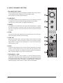
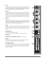
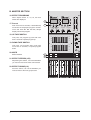
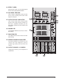
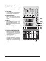
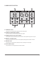
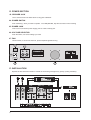
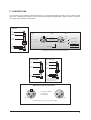
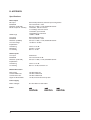
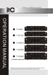
8, 12, 16 CHANNEL
MIC/LINE MIXER
OWNERS MANUAL
A. INPUT CHANNEL SECTION
2~3
B. MASTER SECTION
4~6
C. MIXER OUTPUT SECTION
7
D. POWER SECTION
8
E. INSTALLATION
8
F. CONNECTIONS
9
G. APPENDIX
10
8, 12, 16 Mono Input Channels with silver plated XLRs and balanced Line Inputs
Ultra-low noise discrete Mic Preamps with +48 V Phantom Power
Extremely high headroom - offering more dynamic range
Balanced Inputs for highest signal integrity
Ultra-musical 3-band EQ+FREQ on all mono channels
Peak LEDs all Mono Channels
2 Aux Send per channel for external effects and monitoring
2X256DSP Digital of the effect system inside
Separate Master Mix, Headphone Outputs
2-Track Inputs assignable to Master Mix
Highly accurate 12 segment Bargraph Meters
SAFETY INSTRUCTIONS
CAUTION:
To reduce the risk of electrical shock, do not remove
the cover (or back). No user serviceable parts inside;
refer servicing to qualified personnel.
CAUTION
RISK OF ELECTRIC SHOCK
DO NOT OPEN
WARNING: To reduce the risk of fire or electrical shock, do not
expose this appliance to rain or moisture.
This symbol, wherever it appears, alerts
you to the presence of uninsulated
dangerous voltage inside the enclosure
- voltage that may be sufficient to constitute a risk of shock.
This symbol, wherever it appears, alerts
you to important operating and maintenance instructions in the accompanying
literature. Read the manual.
1
A. INPUT CHANNEL SECTION
1
MIC
1. BALANCE INPUT (MIC)
Electronially Balanced inputs acceptable a standard XLR male connector.
+ 48V Phantom Power available on each input Mic socket.
and this switch is on Rear Phantom Power.
1
2. LINE INPUT
The unbalanced Mic input is provided for the use of an unbalance mic and
is designed to accept an unbalanced high impedance input signal.
(This use for connection Deck, Turntable, Keyboard etc..)
LINE
2
INSERT
3. INSERT
The INSERT is a break point in the input channel signal path. It allows
the signal to be taken out from the mixer, through an external equipment
such as a compressor, and then back to the mixer to continue the final
mix output.
3
4. TRIM
This has a function which adjusts the input sensitivity of each channel in
order to input the constant level of the signal.
5. LOW CUT
Slide down the slide-switch, insert the 18 dB per octave 75Hz low cut filter
in the signal path. This low cut filter is useful on live vocals to reduce
stage rumble or "popping" from microphones. It can also be used to cut
off low frequency hum.
-10
TRIM
4
5
+4
LOW CUT
75 Hz
0
HIGH
6
6. HIGH
Control the high frequency tone of each channel. Always set this control
to the 12 o'clock position, but you can control the high frequency tone
according to the speaker, the conditions of listening position and listener's
taste. Clockwise rotation of the control increases level.
12KHz
-15
+15
0
MID
2.5KHz
7
-15
+15
1.1
7. FREQUENCY + MID
This equalization has a “bell” response i.e. having reached maximum
amplification or attenuation at the selected frequency, the amplitude response
returns to zero either side of that frequency. The FREQ at which this occurs
is variable between 250Hz. The GAIN is variable between ±15dB at the
selected frequency with a fixed q of 1.5Q is a factor a bandwidth.
2
FREQ
.25
6
8. LOW
Control the low frequency tone of each channel. Always set this control
to the 12 o'clock position, but you can control the low frequency tone
according to the speaker, the conditions of listening position and listener's
taste. Clockwise rotation of the control increases the level.
0
LOW
8
80Hz
-15
+15
0
9. AUX 1,2
This is normally derived after the EQ section and channel fader (PREFADER, POSE-EQ), and is therefore unaffected by the fader position and
routing status. This makes the send particularly suitable for foldback or
monitor feeds, which need to be controlled separately from the main P.A.
Mix. All pre-fade sends may be selected internally to be PRE-FADER,
PRE-EQ.
AUX1
+15
9
0
AUX2
+15
0
EFX1
10. EFX1,2
This is normally derived after the EQ and channel fader (POST FADER,
POST EQ), and is therefore follow any changers in fader level. They are
normally used to drive effects processing units which are fed back into the
mixer and which must fade out with the input channel.
PRE
+15
10
0
POST
EFX2
+15
11. PAN
The pan control sends continuously variable amounts of the post fader
signal to either the left or right and G1 or G2 main busses. In the center
position equal amounts of signal are sent to the left and right or G1 & G2
busses.
12. STEREO (L-R)
Push the switch, can use ST L-R fader.
During the stereo L-R switch pushed, you can't use ST L-R fader.
11
PAN
L
12
L-R
13
G1-2
R
13. GRPS 1-2
Push the switch, can use GROUP 1-2 fader.
During the G1-2 switch pushed, you can't use stereo L-R fader.
14
dB
10
14. PEAK
PEAK
5
A red LED indicates a signal level at the insert return point, premaster
fader, it illuminates at approximately 5 dB below clipping.
0
5
15. CHANNEL FADER
This is function to adjust the volume of signal connection into each
channel and adjust the volume of output, together with master fader.
Normal operating position is at the “O” mark, providing 4dB of gain adove
that point, if required.
15
10
20
30
40
50
60
1
3
B. MASTER SECTION
16. EFFECT PROGRAMS
(*)
When adjust switch 17, 18, 19, 20 more
effects are displayed.
7
M1
M1
M2
16
17
M3
17. Pre-set
Push more than 5 seconds, It automatacally
memorize the displayed program number.
Once Just Push M1. M2. M3. M4, always
display memorized program.
+10
(*)
M4
4
M2
2
M3
0
M4
2
4
18
7
UP
DOWN
MUTE
19
20
UP
DOWN
MUTE
10
AUX SEND1
AUX SEND2
AUX RETURN1
AUX RETURN2
0
0
0
0
-20
L
R
POWER
+15
+15
+15
48V
+15
TAPE IN
0
GRAPHIC EQUALIZER
18. UP TAPE SWITCH
1
+15
One push, one program up push with more
than 5 seconds hi-speed program up.
+12
+12
0dB
0dB
0
2
+15
-12
19. DOWN TAPE SWITCH
63Hz
One push, one program down, push with
more than 5 seconds, hi-speed program
down.
PH LEVEL
-12
150Hz
400Hz
1KHz
0
2.5KHz 6.4KHz 15KHz
+12
+12
0dB
0dB
-12
-12
+15
L-R/G1-2
20. MUTE
Effect ON/OFF.
21
L-R
L-R
PHANTOM
22
G1-2
G1-2
G1-2/
L-R
21. EFFECT STEREO (L/R)
Depressing this switch, can let the EFFECT
you need connect to the main control buses.
22. EFFECT GROUP(1-2)
Push the switch, can let the EFFECT you
need connect to the main group buses.
dB
dB
dB
dB
dB
dB
10
10
10
10
10
10
5
5
5
5
5
5
0
0
0
0
0
0
5
5
5
5
5
5
10
10
10
10
10
10
20
20
20
20
20
20
30
30
30
30
30
30
40
50
60
40
50
60
40
50
60
40
50
60
40
50
60
40
50
60
1
4
EFFECT
2 1
GROUP
2 L
MAIN
R
23. EFFECT LEVEL
Using by this control, you can adjust signal
level of echo repeat & exteral effect.
(*)
7
24. AUX SEND / RETURN
This is used for adjusting volume of AUX
sound, when sending and return AUX
singal to used jack.
25. OUTPUTS LEVEL INDICATOR
+10
(*)
M1
M1
M2
M2
2
M3
M3
0
M4
M4
2
4
25
4
7
UP
24
This is level meter which shows output
levels of left & right channel condition on
the way of operation, therefore, you can
see output condition thru this master level
indication.
DOWN
MUTE
UP
DOWN
MUTE
10
AUX SEND1
AUX SEND2
AUX RETURN1
AUX RETURN2
0
0
0
0
+15
+15
+15
-20
L
R
POWER
48V
27
26
+15
TAPE IN
0
GRAPHIC EQUALIZER
1
+15
+12
+12
0dB
0dB
0
2
+15
-12
26. POWER LED
The POWER LED will be turned on when
strt working.
28
63Hz
27. PHANTOM LED
The LED will be turned on when strt 48V
LED working.
28. STEREO GRAPHIC EQUALIZER
2X7-band equalizer is provided for tone
control over each frequency, and for
precise high quality sound by final tone
control.
29. OUTPUT GROUPS 1-2 FADERS
Using by this control, you can adjust G1-2
output level.
PH LEVEL
-12
150Hz
400Hz
1KHz
0
2.5KHz 6.4KHz 15KHz
+12
+12
0dB
0dB
-12
-12
+15
L-R/G1-2
L-R
L-R
PHANTOM
G1-2
G1-2
G1-2/
L-R
dB
dB
dB
dB
dB
dB
10
10
10
10
10
10
5
5
5
5
5
5
0
0
0
0
0
0
5
5
5
5
5
5
10
10
10
10
10
10
20
20
20
20
20
20
30
30
30
30
30
30
40
50
60
40
50
60
40
50
60
40
50
60
40
50
60
40
50
60
1
EFFECT
23
2 1
GROUP
2 L
MAIN
R
29
5
30. OUTPUT MAIN FADER
(LEFT/RIGHT)
This is a master fader for adjustment for
volume of left/right output. Unity gain is
the top their travel.
(*)
+10
(*)
7
31. TAPE LEVEL
M1
M1
M2
M2
2
M3
M3
0
M4
M4
2
4
4
You can adjust the volume of TAPE in
signal by this when connecting tape in.
7
UP
DOWN
MUTE
UP
DOWN
MUTE
10
AUX SEND1
AUX SEND2
AUX RETURN1
AUX RETURN2
0
0
0
0
-20
L
32. HEADPHONE LEVEL
R
POWER
+15
This is a single volume control sends the
level to the headphones and main
monitors.
+15
+15
48V
+15
TAPE IN
0
GRAPHIC EQUALIZER
1
+15
+12
+12
31
0
2
0dB
0dB
-12
-12
33. L-R / G1-2
+15
When L-R / G1-2 switch up, could monitor
stereo (L-R) output signal, when L-R /G12 switch down, could monitor group (G1-2)
output signal.
63Hz
150Hz
400Hz
1KHz
PH LEVEL
0
32
2.5KHz 6.4KHz 15KHz
+12
+12
0dB
0dB
-12
-12
+15
33
L-R/G1-2
34
34. HEADPHONE JACK
You can monitor working condition by
sound thru the headphone.
35. PHANTOM POWER SWITCH/LED
Depressing this switch applies 48V DC
across all microphone input channels
connectors for remote powering of
condenser microphones.
36. L-R/G1-2 SWITCH
This switch routes the G1-2 mix output to
the STEREO bus, allowing G1-2 bus to be
used two mono subgroups mixed down to
a single output when stereo is not
required.
6
L-R
G1-2
L-R
PHANTOM
35
G1-2
G1-2/
L-R
36
dB
dB
dB
dB
dB
dB
10
10
10
10
10
10
5
5
5
5
5
5
0
0
0
0
0
0
5
5
5
5
5
5
10
10
10
10
10
10
20
20
20
20
20
20
30
30
30
30
30
30
40
50
60
40
50
60
40
50
60
40
50
60
40
50
60
40
50
60
1
EFFECT
2 1
GROUP
2 L
MAIN
29
R
C. MIXER OUTPUT SECTION
37
TAPE
1
2
39
41
MAIN---OUT
REC
LEFT
RIGHT
L
L
L
R
R
R
1
1
2
2
AUX SEND
1
1
AUX RETURN
38
2
2
GROUP
FOOT SWITCH
40
42
37. TAPE INPUT JACK
This jack is to be connected with cassette deck when playing back.
38. STEREO AUX RETURNS & SENDS
This can be used to connect all kinds of effects from outside.
39. STEREO OUTPUT JACK (LEFT / RIGHT)
In this product, the final confirmed sound can be send to main amplifier through XLR & 1/4 jack.
40. GROUP 1-2 OUTPUT JACK
There are to be output with the volume control against inputting signal into GRPS 1-2 board.
41. RECORD JACK
This jack is to be connected with cassette deck when recording the mixed output.
42. FOOT SWITCH JACK
This jack used for converting between foot switch and DSP.
7
D. POWER SECTION
43. SPEAKER JACK
This is same functions as below but the using jack is different.
44. POWER SWITCH
Push marked (1), when you want to operate. The LED (SEE NO, 26) will be turned on when working
45. POWER JACK
This is out of connect the power supply (2 X AC 120V or 230V) jack.
46. VOLTAGE SELECTOR
Push the switch, can select voltage you need.
47. FAN
Use the switch, it can fan the heat out, protect amplifier against burning.
44
43
POWER
RIGHT
SPEAKER OUTPUTS
2X350W @ 4
CAUTION
LEFT
RISK OF ELECTRIC SHOCK
DO NOT OPEN
OPTIONAL USES FOR INSERTS
MONO PLUG
CAUTION:
ATTENTION:
REPLACE WITH THE SAME TYPE FUSE AND RATING.
DISCONNECT SUPPLY CORD BEFORE CHANGING FUSE.
UTILISE UN FUSIBLE DE RECHANGE DE MÊME TYPE.
DEBRANCHER AVANT DE REMPLACER LE FUSIBLE.
AC INPUT/FUSE(10A)
WARNING:
AVIS:
TO REDUCE THE RISK OF FIRE OR ELECTRIC SHOCK. DO NOT
EXPOSE THIS EQUIPMENT TO RAIN OR MOISTURE. DO NOT REMOVE COVER.
NO USER SERVICEABLE PARTS INSIDE. REFER SERVICING TO QUALIFIED PERSONNEL.
45
RISQUE DE CHOC ELECTRIQUE
NE PAS OUVRIR
STEREO
PLUG
INSERT ALL THE WAY IN TO
THE "SECOND CLICK"
TIP OUT TO EFFECTS DEVICE
RING RETURN FROM EFFECTS
DIRECT OUT WITH SIGNAL
INTERRUPTION TO MASTER
FOR USE AS AN EFFECTS LOOP
(TIP=SEND, RING=RETURN)
SERIAL NUMBER
MANUFACTURING DATE
POWER CONSUMPTION: 430W
VOLTAGE SELECTOR
115V/60Hz(10A)
230V/50Hz(7A)
46
47
E. INSTALLATION
Experience tells us that the cables in a studio environment get tangled very quickly (inviting mistakes).
TAPE
INPUT
L&R
OUTPUT
L&R
11
12
MIC
LINE
LINE
INSERT
INSERT
TAPE
MAIN---OUT
1
MIC
2
L
L
R
R
R
1
2
2
AUX SEND
1
1
AUX RETURN
+6
SURROUND
+3
+1
0
-1
-3
L
POWER
8
REC
RIGHT
L
1
MODEL-DVP-3000
AMPLIFIER
DIGITAL
LEFT
-6
dB
R
01
09
17
25
02
10
18
26
03
11
19
27
04
12
20
28
05
13
21
29
06
14
22
30
07
15
23
31
08
16
24
32
2
GROUP
2
FOOT SWITCH
F. CONNECTIONS
You will need a lot of cables for different purposes - see the following figures to make sure you have got the
right ones. Unbalanced equipment may be connected to balanced inputs/outputs. Either use mono 1/4" jacks
or connect ring and sleeve of TRS jacks.
Headphones
Tip =
Left signal
Cable
Output
Ring =
Right signal
Input
Ground
Pin 1
2
Sleeve =
Ground / Shield
1
Pin 2 = (+) Signal
3
2
1
Shield
(+) Signal + Hum
(-) Signal + Hum
Positive
(+)Hum + Signal
Negative
(-)Hum + Signal
3
Pin 3 = (-) Signal
2 x Signal
Tip
Ring
Sleeve
= Signal + 6 dB
RFI and Hum
Strain relief clamp
Compensation of interference with balanced connections
Headphone connection
Unbalanced use of
mono 1/4" jack plugs
Balanced use of
stereo 1/4" jack plugs
Tip =
Signal
Tip =
hot (+ve)
Ring =
cold (-ve)
Sleeve =
Ground / Shield
Sleeve =
Ground / Shield
Tip
Tip
Sleeve
Ring
Sleeve
Strain relief clamp
Strain relief clamp
For connection of balanced and
unbalanced plugs, ring and sleeve have
to be bridged at the stereo plug.
Balanced use with XLR connectors
2
1
3
1 = Ground / Shield
2 = hot (+ve)
3 = cold (-ve)
1
Input
2
3
Output
For unbalanced use pin 1 and pin 3 have to be bridged
Different plug types
9
G. APPENDIX
Specifications
Mono Inputs
TRIM range
electronically balanced, discrete input configuration
10 Hz to 60 kHz ± 3 dB
0.01% at +4 dBu, 1 kHz, Bandwidth 80 kHz
-129.5 dBu, 150 Ohm source
-117.3 dBqp, 150 Ohm source
-132.0 dBu, input shorted
-122.0 dBqp, input shorted
+10dB to +60dB
Line Input
Bandwidth
Distortion (THD&N)
Line level range
electronically balanced
10 Hz to 60 kHz ± 3 dB
0.01% at +4 dBu, 1 kHz, Bandwidth 80 kHz
+10 dBu to -40 dBu
Equalization
Hi Shelving
Mid Range
Lo Shelving
12 kHz +/-15 dB
2.5 kHz +/-15 dB
80 Hz +/-15 dB
Mic Input
Bandwidth
Distortion (THD & N)
Mic E.I.N (22 Hz - 22 kHz)
Steroe inputs
Line Input
Bandwidth
Distortion (THD & N)
unbalanced
10 Hz to 55 kHz ±3 dB
0.01% at +4 dBu, 1 kHz, bandwidth 80 kHz
Equalization
Hi Shelving
Lo Shelving
12 kHz +/-15 dB
80 Hz +/-15 dB, Q fixed 2 oct
Master Mix section
Max Output
Aux Send Max Out
Control Room Out
Signal-To-Noise Ratio
+22 dBu balanced
+22 dBu unbalanced
+22 dBu unbalanced
112 dB, all channels at Unity Gain
Power supply
Mains Voltages
Power
10
AC 120V 60Hz or 230V 50Hz