1
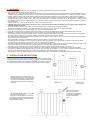
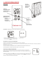
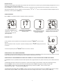
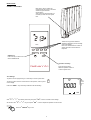
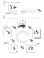
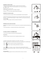
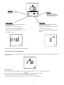
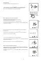
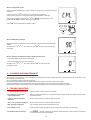
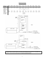
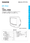
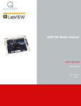
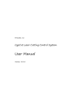
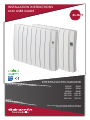
INSTALLATION INSTRUCTIONS
AND USER GUIDE
IECEE
CB
SCHEME
INTERTIA ELECTRIC RADIATOR
RKS4Hi
RKS6Hi
RKS8Hi
RKS10Hi
RKS12Hi
RKS14Hi
RKS4L
RKS6L
RKS8L
RKS10L
RKS12L
RKS14L
Please read these instructions before installing or
using this appliance for the first time
1. - WARNING
•
•
•
•
•
•
•
•
•
•
•
•
•
•
•
•
•
•
•
•
•
The warranty of the heater will not cover any damage caused by non observance of any of these instructions.
This guide must be kept and given to any new owner.
This appliance can be used by children aged from 8 years and above and persons with reduced physical, sensory or mental capabilities or lack of
experience and knowledge if they have been given supervision or instruction concerning use of the appliance in a safe way and understand the
hazards involved. Children must not play with the appliance. Cleaning and user maintenance must not be made by children without supervision.
Children aged from 3 years and less than 8 years shall only switch on/off the appliance provided that it has been placed or installed in its
intended normal operating position and they have been given supervision or instruction concerning use of the appliance in a safe way and
understand the hazards involved. Children aged from 3 years and less than 8 years shall not plug in, regulate and clean the appliance or perform
user maintenance.
Children of less than 3 years should be kept away unless continuously supervised.
CAUTION: Some parts of this product can become very hot and cause burns. Particular attention has to be given where children and
vulnerable people are present.
Should the heater be moved and reinstalled, it is essential that the work is carried out by a competent electrician.
The use of these heaters is forbidden in any area where there is a presence of gases, explosives or inflammable objects.
Neither the connecting cable nor any other object must come into contact with the hot unit.
Check that the voltage shown on the rating plate on the heater is the same as the voltage of the supply to which connection is to be made.
WARNING: In order to avoid overheating, do not cover the heater. Do not use this heater to dry clothes.
The air outlet at the top of the thermal radiator and the air inlet at the bottom are provided to ensure the most efficient operation of the appliance.
They also protect the heater from overheating; therefore, it is essential that at no time are they covered.
This heater should be switched off at the isolating switch before any repair work is carried out. This action should also be taken during the times
of the year when heat is not required.
The thermal radiator should not be installed just below an electrical socket or in front of a socket outlet.
The appliance must be installed in such a way that switches and other control devices cannot be touched by a person using a bath or shower.
The installation must be carried out in accordance with the current electrical regulations.
2
The heater is fitted with a flexible cable size 3 x 1.00 mm for electrical connection. It may be used to connect the heater to the fixed wiring of the
premised through a suitable connection box positioned adjacent to the heater. This appliance must be earthed.
The supply circuit to the heater must incorporate a double pole isolating switch having a contact separation of at least 3 mm.
If the flexible supply cord is damaged, it must be replaced by a repair workshop recognised by the manufacturer, in order to avoid hazard.
All models are supplied with an electrical interrupt cut-out. This will switch off the heater if, for any reason, it overheats. Should the cut-out
operate, turn the heater off and remove the cause for the overheating. The cut-out will be reset automatically.
The presence in the air of particles of smoke, dust and other pollutants could, in time, discolour the walls and surfaces around the heater.
2. - INSTALLATION INSTRUCTIONS
Shelf
- Open the package and check that it is the correct model and it is in good condition.
- To obtain optimum performances it is necessary to maintain a minimum clearance of
15 cm between the radiator and any inflammable material as furniture, curtains etc.
- The rest of clearances required to maintain are indicated on the following figure:
Mínimum 15cm
Closest
object to
the left
end
Position and fix the brackets at the correct
distance from the floor. It is possible to use
the radiator as measuring unit by positioning
it on two polyester package elements and
placing two supports above as indicated on
the figure:
Closest
object to the
right end
Mínimum
15cm
Mínimum 10cm
Mínimum 25cm
Control panel side
Mark the fixing points on
the wall using a pencil
through the two fixing holes
in the square brackets and
perform corresponding
bores.
- The studs and screws to attach the supports
are in the accessories bag.
- Hang the unit on the hooks of the brackets.
- By turning the screw the metallic square will
go downwards, retaining the heater. Repeat
this on the other bracket.
2
3. - USING THE THERMAL RADIATOR
Main switch.
All models are
equipped with one
switch on the back
surface allowing
the heater
disconnection.
MODELS RKSHi
ON
ON/OFF key:
Push the button to switch
on/off the heater. Also you
may lock/unlock the
keyboard by maintaining it for
several seconds.
OPERATION MODE KEY:
Press the key to select
operation mode:
permanent COMFORT,
permanent
ECONOMICAL,
permanent FROST
PROTECTION
AUTOMATIC modes.
“+”
Key
:
Press the key to
increase the
COMFORT set point
temperature.
“-”
Key
:
Press the key to
decrease COMFORT
set point temperature.
.
LCD DISPLAY: LCD display shows the information related to the heater operation.
ON
Example of the heater permanent COMFORT mode,
Set point temperature is 20.5ºC, showing ON output
condition.
The heater is OFF.
ADJUSTMENT OF THE SET POINT TEMPERATURE
COMFORT set point temperature may be adjusted from 7ºC to 30ºC in 0.5ºC steps.
“+” “–”
Pressing the keys
or
the set point temperature is increased/reduced respectively. After three seconds if no other key is pushed the
selected value is stored in memory.
The set point temperature in ECONOMIC mode is the COMFORT setting temperature reduced by 3.5ºC.
The setting temperature in FROST-PROTECTION mode is 7ºC and it is constant.
CORRECTION OF TEMPERATURE MEASURES
If there is a difference between temperature values on an external thermometer and the temperature
displayed by the unit, it is possible to change the sensor settings in order to balance the difference (-5ºC to
+5ºC, in 0.5ºC steps).
In order to make changes hold the “mod.” key for more than five seconds and after that with buttons
“–”
“+”
increase or decrease the correction to 0.5ºC respectively. Press the “mod.” key to store the
correction in memory and proceed with the next setting.
or
3
BLUE BACKLIGHT
Pressing any key the display will illuminate with a soft blue color. After certain time if no other keys are pushed the display backlight will turn off. It is
also possible to adjust the display backlight time.
Hold the “mod.” key during five seconds. After the correction, (if required) of the thermostat (see previous paragraph), a value from 0 to 90
seconds will be displayed. It may be modified in 15 seconds steps by
“+” and “–” keys. If 0 value is selected, the display backlight will be off
permanently. To store, press the “mod.”key.
OPERATION MODES
By the “mod.” key different functions or operation modes may be selected.
ON
ON
PERMANENT COMFORT mode.
“+” “–”
Push the key
or
if it is
required to modify comfort set
point temperature.
ON
PERMANENT
FROST-PROTECTION mode.
The set point temperature is
7ºC and it is constant.
PERMANENT ECONOMICAL
mode. The set point temperature is
reduced by 3.5ºC.
AUTOMATIC mode. In this mode
programs from the input command
cable (pilot wire) are performed.
KEYBOARD LOCK
“
”
In every operation mode it is possible to lock the keyboard by holding the ON/OFF key for more than 7
seconds.
When the keyboard is locked, if any button is pressed, the display will show
not respond.
“
“Lo”message and the unit will
”
To unlock the keyboard press the ON/OFF button for more than 7 seconds.
>7 sec.
OPERATION WITH A PILOT WIRE PROGRAMMER.
It is possible to control the heater operation from a remote pilot wire programmer in AUTOMATIC mode. Pilot wire programmer orders for OFF and
FROST PROTECTION are prior and independent from the operation mode selected in the heater.
OPERATION WITH A PROGRAMMER WITH POWER LINE CARRIER OR A LOAD-CONTROLER WITH POWER LINE CARRIER.
In AUTOMATIC mode, it is possible to control the heater operation from a programmer with PLC (Power Line Carrier) or from a load-controler with
PLC.
TO ASSOCIATE the heater, switch the PLC programmer or the PLC load-controller to the “association” mode (see corresponding manual).
Press the “mod.” button for more than five seconds and after that press the “mod.” button twice, the display will show “CP”,
Keep the “mod.” button pressed. The message “CP” will start blinking. Release the “mod.” button and press it again.
The display will show “En”. To store, press the “mod.”key.
TO DISASSOCIATE the heater press the “mod.” button for more than five seconds and after that press the “mod.” button twice, the display
will show “CP”. Keep the “mod.” button pressed for 60 seconds until the display will show “An”. To store, press the “mod.”key.
4
MODELS RKSL
CONNECT / DISCONNECT
Main switch. All the models are
equipped with the switch on the back
surface for general heater
disconnection.
After a long-term disconnection it is
necessary to reset the unit system
time.
c
These four keys perform different
operations depending on the message
of the LCD display.
Press two central buttons at a time for
several seconds to lock/unlock the
keyboard.
PROG
ON/OFF key:
Press the key to switch from
OFF to OPERATION
Operation mode key:
Press the key to select
different operation modes or
to set the system time.
Time Settings
To perform correct programming it is necessary to set the system time.
1
2
3
4
5
6
7
To set the system time the unit should be in OFF position, with a symbol
on the display.
Press the “mod.” key. Week days indication will start blinking.
OK
“+” or “–” keys select present day and press “OK” to store. Proceed to time settings.
Set the hour with “+” or “–” keys and press “OK” to store. Repeat the operation to set minutes.
With
“
”
Press the ON/OFF key to exit.
5
days
of the
week
ON/OFF
The heater may operate only in one of two conditions; ON or OFF.
OFF:
c
To switch on the unit to ON mode press the key:
Last operation mode before the unit had been switched off
will be displayed. Press the same key to switch off the unit
and pass to OFF.
Apply preferably this form to switch off the unit instead of the
main switch in order to avoid setting the system time
constantly.
PROG
When the unit is in OFF, symbol
is displayed together with premises
temperature value.
ON:
Different operation modes may be applied. To switch from one mode to another press the “mod.” key after no less than two seconds between
each change.
AUTO
c
0h 2
4
6
1
2
3
4
5
6
7
AUTOMATIC INTERNAL
PROGRAMMER MODE
8 10 12 14 16 18 20 22 24
PROG
PERMANENT
FROST PROTECTION
MODE
AUTO
c
c
AUTOMATIC REMOTE
PROGRAMMER MODE
PERMANENT
ECONOMICAL
MODE
PERMANENT
COMFORT
MODE
c
c
6
PERMANENT COMFORT MODE
In permanent comfort mode the unit maintains constantly the set point temperature.
It is possible to modify COMFORT set point temperature in 0,5ºC steps by pressing the
“+” “–”
c
keys
or
.
Temperature range is from 5 to 30ºC.
ON
When the heater consumes power, ON message is displayed.
Pressing the
“i” will momentarily display the premises temperature.
PERMANENT ECONOMICAL MODE
In economical mode the unit maintains all the time the ECONOMICAL set point temperature.
Originally the economical set point temperature is the comfort set point temperature reduced by 3.5ºC.
c
See menu 1 of CONFIGURATION paragraph to modify the reduction or even to select economic set
point temperature.
Pressing the
“i”key displays momentarily the premises temperature.
PERMANENT FROST PROTECTION MODE
In permanent frost protection mode the unit will operate when the premises temperature decreases lower
than 7ºC.
c
In this mode pressing the “i” key displays momentarily the premises temperature.
AUTO
AUTOMATIC INTERNAL PROGRAMMER MODE
In this mode the unit performs commands of the internal programmer.
c
Programming
By default the program “Comfort fro 8h to 22h is applied for all days of the week.
0h 2
4
6
1
2
3
4
5
6
7
8 10 12 14 16 18 20 22 24
PROG
To modify the program press the “PROG” key in this mode or in OFF mode.
1
2
3
4
5
6
7
PROG
Select the temperature level for the first time interval of the day 1 by pressing one of the following keys:
Pressing
displays two segments indicating COMFORT temperature.
Pressing
display one segment indicating ECONOMICAL temperature.
0h 2
Pressing
does not display any segment, indicating FROST PROTECTION temperature.
After programming all 24 intervals for the DAY 1, press “OK” to pass to the DAY 2 of the week and repeat
the procedure.
Fast Programming
To copy the complete program from one day to another hold the “OK” key for 3 seconds.
7
4
6
8 10 12 14 16 18 20 22 24
OK
AUTO
c
PROG KEY
0h 2
Press the key to modify
the program
4
6
1
2
3
4
5
6
7
INFO KEY
8 10 12 14 16 18 20 22 24
PROG
Press the key to see the
premises temperature or set
point temperature, according to
configurations of MENU 5
SAND GLASS KEY
ABSENCE KEY
Press the key to adjust the specified temperature for
certain determined time.
Press the key to switch on the Frost Protection
mode from 1 day to 365 days.
By keys
“+” or “–” adjust the set point
Adjust the amount of absence days by keys
“ ”
“–”
temperature and store by pressing the OK .
Adjust the time required by keys
“ ”
press OK
“+”
or
, and store with OK key.
To disconnect the absence mode press again the
“+” or “–” and
“OK” key.
to store.
OK
OK
“ ”
To go back to the previous settings press again the OK key.
AUTOMATIC REMOTE PROGRAMMER MODE
In this mode the unit follows commands from the remote control desk or remote programmer. If there aren’t any, the unit operates in permanent
COMFORT mode.
AUTO
c
KEYBOARD LOCK
En every operation mode it is possible to lock the keyboard pressing central
“+” and “–” keys for several seconds.
bloc
With the keyboard locked pressing any key displays
message and the unit will not respond,
With the keyboard locked the unit may receive commands from the IR remote control.
To unlock the keyboard press simultaneously central keys
“+” and “–” for several seconds.
8
CONFIGURATION
It is possible to configure various parameters of the unit.
“
c
”
In OFF mode press for 10 seconds ON/OFF key to enter the first configuration
menu. It is necessary to pass through five menus to exit the configuration. The
Menu number is displayed above in the right part of the display.
PROG
>10 sec.
Menu 1: Adjusting the ECO set point temperature.
By default the Economic set point temperature value is equal to
comfort temperature value reduced by 3,5ºC.
1
2
3
4
5
6
7
The reduction value may be modified from 0 a 10ºC in 0,5°C steps.
For this purpose modify the value with the keys
and pass to the next setting.
“+” / “–” and press “OK” to store
c
OK
1
2
3
4
5
6
7
ECO set point temperature value may be stored independently from the CONFORT
temperature value.
To authorize ECO value modification press and hold the
message "
“+”key until it displays the
---- and store pressing “OK”.
OK
In such a way when selecting the permanent economical mode it
will be possible to assign any temperature with
permanent economical mode.
“+” or “–” key displayed at selection of
Selection range will start from 4.5ºC to the comfort set point temperature.
c
Menu 2: Correction of temperature measures.
If there is a difference between an external thermometer indication and the temperature
displayed by the unit, in menu 2 it is possible to influence on the sensor in order to balance
the difference. (-5ºC to +5ºC,) in 0,1ºC steps.
To modify press the keys
next setting.
“+” or “–”, after press the “OK”
key and proceed with the
c
OK
9
1
2
3
4
5
6
7
número
de menú
Menu 3: Configuration of CPL
1
2
3
4
5
6
7
This menu allows associating the unit to the remote CPL programmer connected to the same
power grid.
“+”
In menu 3 press the
for 5 seconds. CPL message will start blinking.
Switch the CPL programmer, remote control desk to the “association” mode (see
corresponding manual). Press shortly the
“+”key. “EnrE” message displays on the
screen and then "CPL" message confirming the association.
OK
“ ”
Press OK key to proceed with the following setting.
>5 sec.
1
2
3
4
5
6
7
Menu 4: Backlight time settings
Adjustable backlight is available from 0 to 225 seconds in 15 seconds steps (90 seconds by
default).
To modify press
next setting.
“+” or “–”, keys, then press the “OK” to store and proceed with the
OK
Menu 5: Selection of temperature display in AUTO operation mode.
1
2
3
4
5
6
7
1 = Permanent display of the premises temperature.
0 = Permanent display of the set point temperature.
“+” or “–”, keys, then press the “OK” to store and exit the
To modify press
configuration mode.
OK
4. - CLEANING AND MAINTENANCE
The radiators do not precise any special maintenance providing thermal comfort during large periods. Clean dust with a dry, soft cloth only when
the unit is disconnected and cold.
Do not use solvents or abrasive products for cleaning.
After the heating season disconnect the radiator with the switch located on the back surface of the radiator.
This thermal radiator has been manufactured under an assured quality system using environment friendly processes.
Please take the heaters to a clean point once their useful life is finished, in order to recycle their materials in the right way.
5. - TROUBLESHOOTING
- The thermal radiator does not heat.
Check the heater or the air inlets are not covered.
- The room does not reach the
required temperature.
Check the selected temperature is in accordance with the desired temperature. Maybe the room needs
more heating power.
- “-9.9ºC” ó “99.9ºC” message is
displayed
Sensor wrong connection. Contact the after sale service.
- “d2” or “d3” message is displayed
Sensor wrong connection. Contact the after sale service .
-“dEF” message is displayed
CPL connection trouble. Contact the after sale service.
- Time settings are lost
There was electric supply shortage or the unit had been disconnected by the main switch
- The keyboard does not respond
If the
message is displayed, the thermal radiator keyboard is locked. Hold two central keys
for several seconds to unlock the keyboard.
bloc
10
SPECIFICATIONS
Models (Hi, L)
ELEMENTS
LENGTH (cm)
RKS4Hi
RKS6Hi
RKS8Hi
RKS10Hi
RKS12Hi
RKS14Hi
RKS4L
RKS6L
RKS8L
RKS10L
RKS12L
RKS14L
4
6
8
10
12
14
4
6
8
10
12
14
41.5
57.5
73.5
89.5
105.5
121.5
41.5
57.5
73.5
89.5
105.5
121.5
WIDTH(cm)
10 plus 2.5 cm separation from the wall
HEIGHT (cm)
58
WEIGHT
8 kg
11 kg
14 kg
17 kg
20 kg
23 kg
8 kg
11 kg
14 kg
17 kg
20 kg
23 kg
POWER
500W
750W
1000W
1250W
1600W
2000W
500W
750W
1000W
1250W
1600W
2000W
ISOLATION
VOLTAGE
CLASS II
220-240V~
RKS-L
RKS-Hi
Connect the black wire marked “Fil Pilote“ to the signal wire when available. Do not connect this wire to any EARTH lead.
Connect “L” and “N” wires to a fix wall socket or to an appropriate plug WITHOUT EARTH.
11
WARNING:
In order to avoid overheating do not cover the heater.
The symbol on the product or in its packaging indicates that this product may not be treated
as household waste. Instead it shall be handed over to the applicable collection point for the
recycling of electrical and electronic equipment. By ensuring this product is disposed of
correctly, you will help prevent potential negative consequences for the environment and
human health, which could otherwise be caused by inappropriate waste handling of this
product. For more detailed information about recycling of this product, please contact your
local city office, your household waste disposal service or the shop where you purchased the
product. These instructions are only valid in the EU member states.
ELNUR UK Ltd.
Unit 1, Brown Street North
Leigh, Lancashire
WN7 1BU
www.elnur.co.uk
Customer Service Department:
Telephone +44(0)1942 670119
[email protected]
Manufactured by:
ELNUR, S.A.
Madrid, Spain
www.elnur-global.com
[email protected]
Management System International Certifications:
As a part of the policy of continuous product improvement Elnur reserves the right to alter specifications without notice.
INSTALLATION INSTRUCTIONS AND USER GUIDE WEB VERSION